
Use and Care Manual


7
Features
In this section, refer to Figure 1 except where
otherwise specified.
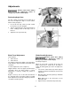
Miter Cutting Head
The miter cutting head (Figure 1) is the unit that
cuts the material and consists of a cast iron
base, blade support unit and guard,
transmission unit, and motor. The depth of cut is
set by adjusting the depth cut stop. The miter
cutting head swivels and can be adjusted from
0–45º.
Miter Positioning
The cutting angle (miter position) is manually
adjusted and described in Performing Angle
Cuts on page 10.
Self-centering Vise
The self-centering vise holds the work piece in
place during cutting. The work piece is secured
in the vise by turning the vise handle.
Trigger Handle
The trigger handle is located on the operating
lever used to raise and lower the saw. It
contains a micro-switch (Figure 9), which starts
the saw when pressed.
Flood Coolant System
Coolant is dispensed directed onto the saw
blade from a coolant fitting on the upper blade
guard. Coolant is provided through tubing from
the coolant pump mounted on the back of the
motor casing.
The coolant flow control valve (Figure 2) is
located on the back of the saw. Adjust the valve
to achieve desired flow. Flow starts when the
switch on the machine is turned on and the
micro-switch in the trigger handle is depressed.
Releasing the micro-switch stops coolant flow.
This coolant system can operate with either a
soluble oil base coolant or water-soluble
synthetic coolant. Coolant should be changed
regularly. Some recommended brands are DoAll
and Lenox. These coolants are available at your
local industrial distributor.
Figure 1
Figure 2