
Use and Care Manual


14
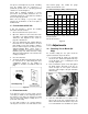
10.8 Setting Blade Speed
1. Disconnect band saw from power source.
2. Open the pulley cover.
3. Loosen the knob (see A, Figure 3) and lift up
on the motor. Move the belt to the desired
pulley grooves. A chart is affixed to the inside
of the belt guard showing the positions for the
three speeds, 80, 120 and 200 surface feet per
minute (SFPM). This chart is also shown in
Figure 16.
Figure 16
4. Push the motor back down to tension the belt,
and tighten the knob (A, Figure 3).
Material chips or shavings are the best indicator of
proper blade speed and downfeed rate. The ideal
chip is thin, tightly curled and warm to the touch.
Chips that range from golden brown to black
indicate excessive force. Blue chips indicate
extreme heat from too high a blade speed, which
will shorten blade life. Thin or powdered chips
indicate insufficient downfeed rate.
10.9 Belt Tension
1. Disconnect band saw from power source.
2. Open the pulley cover.
3. Loosen the knob (see A, Figure 3), and push
down on the motor to tighten the belt.
4. Tighten the knob (A, Figure 3).
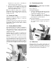
5. Check the tension by using moderate finger
pressure about midway between the pulleys.
The belt should deflect about 1/2”. See Figure
17.
6. Close the pulley cover.
Figure 17
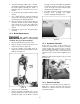
10.10 Blade Guide Assembly
The blade guide assembly should be moved as
close to the workpiece as possible without
interfering with the cutting operation. This allows
minimum exposure of the blade. To adjust, loosen
handle (A, Figure 18) and slide the assembly into
position. Always tighten handle (A, Figure 18) after
adjustment.
Figure 18
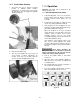
10.11 Guide Bearings
The blade guide bearings come pre-adjusted from
the factory, but should be inspected frequently and
future adjustments made as needed, especially
after changing blades.
The blade should have already been tensioned
and tracked properly before adjusting the blade
guides.
1. Disconnect band saw from power source.
2. Loosen slightly the hex cap screw (B, Figure
18) with a 12mm wrench.
3. Slide the guide block (C, Figure 18) down until
the thrust bearing (D, Figure 18) just contacts
the back edge of the blade.
4. Tighten the hex cap screw (B, Figure 18).