Operating Instructions and Parts Manual 5 x 6-inch Horizontal Band Saw Model HBS-56S For use with machines with Serial Numbers 06080307 and higher WMH TOOL GROUP 2420 Vantage Drive Elgin, Illinois 60124 Ph.: 800-274-6848 www.wmhtoolgroup.com Part No.
Warranty and Service WMH Tool Group, Inc., warrants every product it sells. If one of our tools needs service or repair, one of our Authorized Service Centers located throughout the United States can give you quick service. In most cases, any of these WMH Tool Group Authorized Service Centers can authorize warranty repair, assist you in obtaining parts, or perform routine maintenance and major repair on your JET® tools. For the name of an Authorized Service Center in your area call 1-800-274-6848.
Table of Contents Warranty and Service.................................................................................................................................... 2 Table of Contents.......................................................................................................................................... 3 Warning ......................................................................................................................................................... 4 Introduction ....
Warning 1. Read and understand the entire owner's manual before attempting assembly or operation. 2. Read and understand the warnings posted on the machine and in this manual. Failure to comply with all of these warnings may cause serious injury. 3. Replace the warning labels if they become obscured or removed. 4. This band saw is designed and intended for use by properly trained and experienced personnel only.
blahblahblah 20. Make your workshop child proof with padlocks, master switches or by removing starter keys. 21. Give your work undivided attention. Looking around, carrying on a conversation and “horse-play” are careless acts that can result in serious injury. 22. Maintain a balanced stance at all times so that you do not fall or lean against the blade or other moving parts. Do not overreach or use excessive force to perform any machine operation. 23. Use the right tool at the correct speed and feed rate.
Introduction This manual is provided by WMH Tool Group covering the safe operation and maintenance procedures for a JET Model HBS-56S Horizontal Band Saw. This manual contains instructions on installation, safety precautions, general operating procedures, maintenance instructions and parts breakdown. This machine has been designed and constructed to provide years of trouble free operation if used in accordance with instructions set forth in this manual.
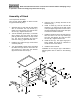
Shipping Contents Compare the contents of your container with the following parts list to make sure all parts are intact. Missing parts, if any, should be reported to your distributor. Read the instruction manual thoroughly for assembly, maintenance and safety instructions. Open carton and check for shipping damage. Report any damage immediately to your distributor and shipping agent. Do not discard any shipping material until the band saw is assembled and running properly.
Read and understand the entire contents of this manual before attempting set-up or operation! Failure to comply may cause serious injury. Assembly of Stand Tools required for assembly: Two 1/2-inch wrench (Note: A ratchet wrench may speed assembly time.) 5. Insert the axle (J) through the holes of the wheel base (H). 1. Assemble left (A) and right (B) side plates with six 5/16"x3/4" hex cap screws (C1), twelve 5/16” flat washers (D1) and six 5/16" hex nuts (E1). Tighten the hex nuts. 6.
Assembly of Band Saw Tools required for assembly: – cross point (Phillips) screwdriver – 3mm and 4mm hex wrenches (provided) – 1/2" and 9/16" wrenches Remove any plastic or holding straps from around the band saw. Areas of the machine have been given a protective coating at the factory. This should be removed using a soft cloth moistened with kerosene or a cleanerdegreaser. Do not use gasoline, paint thinner, or lacquer thinner as these will damage painted surfaces. Do not use an abrasive pad.
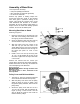
4. Lift up on the motor and install the belt around the pulley grooves, as shown in Figure 4. Allow the motor to drop back down, then push it down farther to tension the belt. (For further information on belt tension and belt position on the grooves, see page 15.) 5. Tighten the knob (A, Figure 3). 6. Close the pulley cover and secure it with the pan head screw and hex nut. Figure 4 Stock Stop The stock stop is used for making multiple cuts of the same length. 1.
This band saw is pre-wired for 115 volt and is equipped with an electric cord having an equipment-grounding conductor and a grounding plug similar to that shown in Figure 6. The plug must be inserted into a matching outlet that is properly installed and grounded in accordance with all local codes and ordinances. Do not modify the plug provided. If it will not fit the outlet, have the proper outlet installed by a qualified electrician.
1. Disconnect machine from power source. 2. Open the switch box and connect the leads according to the wiring diagram inside the switch box. This diagram is also shown on page 26 of this manual. 3. The 115V attachment plug supplied with the band saw must be replaced with a UL listed plug suitable for 230 volt operation, similar to the one shown in Figure 8. Contact your local authorized WMH Tool Group service center or qualified electrician for proper procedures to install the plug.
4. If the vise and blade are square but the pointer (D, Figure 10) is off slightly, loosen the screw and adjust the pointer until it lines up with zero on the scale. Tighten the screw. NOTE: The handle (A, Figure 10) is adjustable. Simply lift up on the handle and rotate it on the pin. Release the handle, making sure it seats itself properly on the pin. Setting 45° Stop Swivel the bow to the 45° angle. Use a machinist’s protractor or similiar 45° device to check the blade’s angle to the vise.
3. Slide the movable jaw by hand until the jaw contacts the workpiece. 4. Rotate the vise handwheel clockwise to reengage the lead screw, and continue the tightening process of the jaw until the workpiece is securely clamped. 5. The quick release function can be used to back off the movable jaw when the cut is finished. Miter Cuts There are two sets of holes in the base for mounting the vise assembly. For miter cuts from 0° up to 45°, mount the vise assembly to the rear set of holes.
Blade Tension Use the knob (Figure 15) to tension the blade. Clockwise tightens the blade, counterclockwise loosens it. Blade Tracking Tracking the blade requires that the band saw be operating while the back blade cover is removed. Use extreme caution and keep hands away from blade. The blade provided with your band saw has already been tracked at the factory and requires no adjustment. When the blade is replaced, tracking may be required for the new blade.
Belt Tension 1. Disconnect band saw from power source. 2. Open the pulley cover. 3. Loosen the knob (see A, Figure 3), and push down on the motor to tighten the belt. 4. Tighten the knob (A, Figure 3). 5. Check the tension by using moderate finger pressure about midway between the pulleys. The belt should deflect about 1/2”. See Figure 17. 6. Close the pulley cover.
Blade Replacement Use caution and proceed slowly when working with or around a band saw blade. Use gloves when handling it. 1. Disconnect band saw from power source. 2. Remove the knob and the back blade cover from the band saw. See Figure 19. 3. Loosen the handle on the blade guide (A, Figure 18) and lower the blade guide as far as it will go. See Figure 19. 4. Release tension on the blade. 5. Remove old blade and install new one by placing it between the guides and around the band wheels.
Vertical Bow Position 1. The band saw can be placed in vertical position to facilitate blade changes, maintenance, etc. Unscrew the knob (Figure 22) and slide it out to disengage the hydraulic cylinder. 2. Raise the bow all the way. 3. The stop screw (Figure 23) has been preset at the factory. If further adjustments are needed, loosen the hex nut and rotate the screw as needed. Re-tighten the hex nut. Operation Figure 22 Important: This band saw is designed for dry cutting operations only.
Clean the machine of chips, shavings, etc. with a rag or brush. Do not use your hands. 5. Open the valve on the hydraulic cylinder to allow the bow to descend in a gradual and controlled manner. If the power cord is worn, cut, or damaged in any way, have it replaced immediately. 6. The machine will shut off at the completion of the cut. Remove the workpiece. The ball bearings on the blade guide assemblies are self-contained and sealed. They require no further lubrication. 7.
Troubleshooting Trouble Motor will not start. Band Saw vibrates excessively. Miter cuts not accurate. Cuts not square. Finished surface of workpiece is rough, unsatisfactory. Probable Cause Remedy No incoming power. Check plug connection. Blown electrical panel fuses. Replace fuses. Defective motor, switch, power cable, or plug. Qualified electrician/service personnel should inspect these items. Stand on uneven surface. Adjust stand for even support. Saw blade has cracks.
Parts List: HBS-56S Band Saw Index No. Part No. Description Size Qty 1 ...............TS-0051031 .............Hex Cap Bolt ........................................................ 5/16”x3/4”.................... 4 2 ...............TS-0561011 .............Hex Nut ................................................................ 1/4”.............................. 1 3 ...............TS-0680021 .............Flat Washer.......................................................... 1/4”.............................
Parts List: HBS-56S Band Saw Index No. Part No. Description Size Qty 89 .............OS-15375.................Oil Seal................................................................. .................................... 2 90 .............HVBS462-090 ..........Transmission Wheel Shaft ................................... .................................... 1 91 .............HVBS462-091 ..........Worm Gear........................................................... ....................................
Parts List: HBS-56S Band Saw Index No. Part No. Description Size Qty 313 ...........TS-0208071 .............Hex Socket Head Screw ...................................... 5/16"x1-1/4" ................ 2 314 ...........TS-0267041 .............Set Screw............................................................. 1/4"x3/8"...................... 2 315 ...........HBS56S-315 ............Positioning Ring ................................................... .................................... 1 316 ...........
Parts List Index No. Part No. Description Size Qty 393 ...........HBS56S-393 ............Wire Ring ............................................................. .................................... 1 394 ...........TS-081C032.............Cross Round Head Screw ................................... 10-24x1/2”................... 1 395 ...........TS-0560071 .............Hex Nut ................................................................ 10-24........................... 1 NS-1 .........HVBS463-085-01....
Bow Assembly (Page 2 of 3) 97-1(2) 25
Bow Assembly (Page 3 of 3) 26
Base and Cabinet Assembly 27
Electrical Connections WMH Tool Group 2420 Vantage Drive Elgin, Illinois 60124 Phone: 800-274-6848 www.wmhtoolgroup.