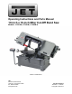
Operating Instructions and Parts Manual 10-inch x 16-inch Miter Cut-Off Band Saw Models: J-7020M, J-7040M, J-7040M-4 Model J-7020M shown JET 427 New Sanford Road LaVergne, Tennessee 37086 Ph.: 800-274-6848 www.jettools.com Part No.
Warranty and Service JET warrants every product it sells against manufacturers’ defects. If one of our tools needs service or repair, please contact Technical Service by calling 1-800-274-6846, 8AM to 5PM CST, Monday through Friday. Warranty Period The general warranty lasts for the time period specified in the literature included with your product or on the official JET branded website. • JET products carry a limited warranty which varies in duration based upon the product.
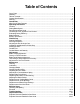
Table of Contents Cover Page .................................................................................................................................. 1 Warranty ....................................................................................................................................... 2 Table of Contents .......................................................................................................................... 3 General Specifications .....................................
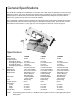
General Specifications The JET Model J-7020M and J-7040M Miter Cut-off Saws cover a wide variety of applications in machine shops, maintenance shops, tool rooms, fabrication and welding shops, and almost any other application requiring a general purpose cut-off band saw. These models offer more standard features designed to provide maximum performance, greater accuracy and more economical operation.
- Misuse of this machine can cause serious injury. - For safety, machine must be set up, used and serviced properly. - Read, understand and follow instructions in the Operating Instructions and Parts Manual which was shipped with your machine. When Setting up Machine: - Always avoid using machine in damp or poorly lighted work areas. - Always be sure the machine support is securely anchored to the floor or the work bench. When Using Machine: - Always wear safety glasses with side shields (See ANSI Z87.
20. Some dust created by power sanding, sawing, grinding, drilling and other construction activities contains chemicals known to cause cancer, birth defects or other reproductive harm. Some ex amples of these chemicals are: Lead from lead based paint Crystalline silica from bricks and cement and other masonry products, and arsenic and chromium from chemicallytreated lumber. 21. Your risk from those exposures varies, depending on how often you do this type of work.
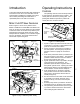
Operating Instructions Introduction This manual includes the operating and maintenance instructions for the JET 10 X 16-inch Miter Cut-Off Saws, Models J-7020M and J-7040M. This manual also includes parts listings and illustrations of replaceable parts for the miter cut-off saws. Miter Cut-Off Saw Features Refer to Figures 1 and 2 for key features of the Models J-7020M and J-7040M Miter Cut-Off Saw.
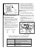
Coolant Pump Switch Coolant Pump Access Panel Machine Base Figure 4: Coolant pump switch Setting Blade Speed 1. The blade speed is controlled by an adjustment mechanism on the right end of the saw. Speed increases when the adjustment knob is turned counterclockwise. Speed decreases when the knob is turned clockwise. 2. A placard on the drive belt guard (shown below) provides recommended speeds for various materials. 3. A speed indicator is provided on the barrel of the adjustment mechanism.
4. To lower the saw head with power off, pull and turn the red knob (manual override) on the electromagnetic valve (see figure 6). If the chips are slightly curled and are not colored by heat — the blade is sufficiently sharp and is cutting at its most efficient rate.
5. When the blade has completed about 1/3 of the cut, increase the feed rate. Watch the chip formation until cutting is at its most efficient rate and allow the saw to complete the cut (see Evaluating Blade Efficiency). The blade is now considered ready for regular service. 3. Loosen hex post to free moveable jaw. Position the moveable jaw so it is parallel to and in contact with the work piece. 4. Using the clamping hand wheel on the worktable, tighten the moveable jaw against the work piece.
Installation and Adjustment of Work Stop The work stop is used to set up the saw for making multiple cuts of the same length (see figure 10). Install and adjust the work stop as follows: Stop Post 5. Start the motor and allow the saw to come up to speed. 6. Slowly set the saw down onto the workpiece. Adjust cutting speed with the feed rate control valve. 7. DO NOT DROP THE SAW HEAD OR FORCE THE CUT. Let the weight of the saw head provide the cutting force. 8.
Coolant Mixture and Quantity The general purpose coolant is a mixture of water soluble oil and water. Mix one part of soluble oil (TRIM SOL) to ten parts of water (one quart oil, ten quarts of water). The eleven quarts of coolant is the amount required for the coolant pump to operate properly. There are numerous coolants on the market that are formulated for special applications.
This assures that the blade is not touching the shoulder of the wheel. 11. Shut off the saw. 12. Hold the hex adjustment screws with a wrench and tighten the center locking screws. Make sure the hex adjustment screws do not move while tightening the center screws. 13. Install the two blade guide bearing brackets. Position the guides so the bearings just touch the blade. 14. Install the left blade guard. 15. Close the saw head cover. Tighten the four knobs. Put Strip Between Wheel and Blade 0.
4. Position the bearing by turning the bushing. Set the clearance at approximately 0.001 inch. The blade should be in a vertical position between the bearings (see figure 15). 5. Tighten the center locking screw with an Allen wrench while holding the eccentric bushing in position with the 3/4-inch wrench. 6. Use the same procedure to adjust the other guide bearing. 7. When the adjustment is correct, the guide bearings should rotate freely with slight pressure of the finger (with the blade stopped). 8.
Lubrication Lubricate the following components at the specified frequencies and using the lubricants defined below: 1. Ball bearings: the bearings are lubricated and sealed—periodic lubrication is not required. 2. Blade guide bearing: the bearings are lubricated and sealed—lubrication is not required. Inspect periodically. 3. Idler wheel bushing: the bearings are lubricated and sealed—lubrication is not required. Inspect periodically. 4.
on the workpiece when the feed rate control valve is fully open. 1. Raise the saw arm to its full upright position and lock it in position (refer to Figure 18). 5. Inspect bearings for damage and smooth operation, Replace if faulty. 6. Install the bearing in the idler wheel. Install the idler wheel on the idler shaft. 7. Install the screw, spring washer and washer in the idler shaft. 8. Install the blade (see Changing blades).
1. Remove the cap screw and remove the carbide guide. Discard the carbide guide. 2. Install the replacement carbide guide on the guide bearing support. Install the cap screw. Set the guide so it just contacts the side of the saw blade. 3. Using a machinist's square, check squareness of the blade to the table. Replacement of Guide Bearings (see figure 20) 1. Remove the cap screw from the bearing being replaced. Separate the bushing and cap screw from the bearing. Discard the bearing.
Electrical Observe the following when connecting to the power source. (Refer to the wiring diagrams in Figures 23 - 26.) WARNING: JET RECOMMENDS THAT ANY HARD WIRING OF THE SAW TO A BRANCH, OR ANY CHANGE OF VOLTAGE SUPPLIED TO THE MOTOR BE PERFORMED BYA LICENSED ELECTRICIAN. 1. Make sure the saw is disconnected from the power source, or that the fuses have been removed or breakers tripped in the circuit in which the saw will be connected.
115V - To reverse motor rotation switch terminal 5 and 6. 220V - To reverse motor rotation hook terminal 6 to 1.
Troubleshooting Fault Probable cause Suggested remedy Excessive blade breakage 1. Material loose in vise. 2. Incorrect speed or feed. 1. Clamp work securely. 2. Check Machinist’s Handbook for speed/feed appropriate for the material being cut. 3. Check Machinist’s Handbook for recommended blade type. 4. Adjust blade tension to the point where the blade just does not slip on the wheel. 5. Start the motor before placing the saw on the workpiece. 3. Teeth too coarse for material. 4.
Blade is twisting 1. Blade is binding in the cut. 2. Blade tension too high. Unusual wear on side/back of blade 1. Blade guides worn 1. Replace blade guides. 2. Blade guide bearings not adjusted. 2. Adjust blade guide bearings. 3. Blade guide bearing bracket is 3. Tighten blade guide bearing loose. bracket. Teeth missing/ripped from blade 1. Blade tooth pitch too coarse for workpiece. 2. Feed too slow; feed too fast. 3. Workpiece vibrating. 4. Gullets loading up with chips. Motor running too hot 1.
Exploded View - Model J-7020M/J-7040M Miter Cut-off Saw Base 22
Parts List - Model J-7020M/J-7040M Miter Cut-off Saw Base ITEM NO. PART NO.
Parts List - Model J-7020M/J-7040M Miter Cut-off Saw Base 24 ITEM NO. 92 92-1 93 94 95 95-1 96 97 98 99 100 101 102 103 103-1 103-2 104 105 106 107 108 109 110 111 112 113 113-1 114 115 115-1 116 117 117-1 117-2 117-3 118 119 120 120-1 120-2 121 122 123 124 125 126 127 128 129 130 131 132 133 134 135 263 PART NO.
Exploded View - Model J-7020M/J-7040M Miter Cut-off Saw Head 25
Parts List - Model J-7020M/J-7040M Miter Cut-off Saw Head ITEM NO. 26 PART NO.
Parts List - Model J-7020M/J-7040M Miter Cut-off Saw Head ITEM NO. PART NO.
427 New Sanford Road LaVergne, Tennessee 37086 Ph.: 800-274-6848 www.jettools.