
Full Product Manual


7
Introduction
This manual includes the operating and maintenance
instructions for the JET 10 X 16-inch Miter Cut-Off
Saws, Models J-7020M and J-7040M. This manual
also includes parts listings and illustrations of
replaceable parts for the miter cut-off saws.
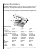
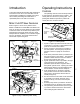
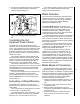
Miter Cut-Off Saw Features
Refer to Figures 1 and 2 for key features of the
Models J-7020M and J-7040M Miter Cut-Off Saw. The
miter cut-off saws are nearly identical to JET's Model
J-7020 and J-7040 cut-off saws except that they are
equipped with a 45 degree swivel head. The swivel
head provides the capability to cut material at angles
from 0 to 45 degrees. The swivel head locks and
unlocks with a quick acting lever.
Saw Head
Blade Guide
Supports
Blade Cover
Belt
Cover
Speed
Control
Coolant
Temperature
Worktable
Pivot Pin
Turn Plate
Blade
Guides
Figure 1: Key Features (Front
View)
Figure 2: Key Features (Rear View)
Drive
Motor
Hydraulic Cylinder
Coolant Valves
Feed Rate
Control
Saw Head
Table
Hard Stop
Base
Work
Table
Counter-
balance spring
Vise
Jaw
(Fixed)
Vise
Jaw
(Moveable)
Operating Instructions
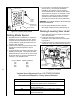
Controls
The operating controls for the saw are provided in
a control panel on the left side of the machine. The
control panel is mounted on a pivoting tube. The
pivoting tube allows the operator to position the
control panel in a convenient location.
1. A power-on light is provided on the left side of the
control panel. The power-on light indicates when
power is connected to the machine.
2. A large, emergency stop button is provided on
the control panel. The emergency stop button
provides a means to rapidly cut off electrical
power.
3. A saw motor pushbutton switch is provided to the
left of the emergency reset button. The sawmotor
pushbutton switch starts the saw motor and the
E-stop button stops the saw motor.
4. A green pushbutton switch is provided to the right
of the emergency stop pushbutton. The
pushbutton opens an electro-magnetic valve in
the hydraulic cylinder circuit. Opening the valves
allows the saw head to move downward and put
the saw blade in contact with the workpiece.
5. A red release button on the electro-magnetic
valve provides a means to lower the saw head
when power to the machine has been discon-
nected (see figure 6).
6. The rate at which the saw head moves downward
is controlled by a hydraulic feed rate control
located on the top, rear of the saw head (see
figure 5).
7. A coolant pump switch is provided on the electri-
cal equipment box on the back of the machine.
8. The quick acting swivel-head lock (refer to Figure
7) is used to release and lock the swivel-head
when making angular material cuts.
Figure 3: Control panel
Emergency
Reset
Button
Saw Head
Pushbutton
Power-on
Light
Motor
Pushbutton