This .pdf document is bookmarked Operating Instructions and Parts Manual Industrial Bench Grinder with Multitool Model JIGM-8 JET 427 New Sanford Road LaVergne, Tennessee 37086 Ph.: 800-274-6848 www.jettools.com Part No.
11. This product, when used for welding, cutting, or working with metal, produces fumes, gases, or dusts which contain chemicals known to the State of California to cause birth defects and, in some cases, cancer. (California Health and Safety Code Section 25249.5 et seq.) 1.0 IMPORTANT SAFETY INSTRUCTIONS 12. Do not operate this machine while tired or under the influence of drugs, alcohol or any medication. WARNING – To reduce risk of injury: 1.
26. Use recommended accessories. The use of improper accessories may cause risk of injury to persons. 35. Never stand on tool. Serious injury could occur if the tool is tipped or if the cutting tool is unintentionally contacted. 27. Turn off the machine before cleaning. Use a brush to remove chips or debris — do not use bare hands. 36. Direction of feed. Feed work into a blade or cutter against the direction of rotation of the blade or cutter only. 28. Never leave the grinder running unattended.
2.0 Table of contents Section Page 1.0 IMPORTANT SAFETY INSTRUCTIONS ....................................................................................................... 2 2.0 Table of contents ............................................................................................................................................ 4 3.0 About this manual .......................................................................................................................................... 5 4.
3.0 About this manual This manual is provided by JET, covering the safe operation and maintenance procedures for a JET JIGMIndustrial Grinder with Multitool attachment. This manual contains instructions on installation, safety precautions, general operating procedures, maintenance instructions and parts breakdown. Your grinder has been designed and constructed to provide consistent, long-term operation if used in accordance with the instructions set forth in this document.
4.0 Specifications Table 1 JIGM-8 577208 Model number Stock number Motor and Electricals Motor type Horsepower Phase Voltage Cycle Listed FLA (full load amps) Start capacitor Run capacitor Motor speed On/off switch Power transfer Power cord Power plug installed Recommended circuit size 1 Sound emission without load 2 Arbor and grinding wheel Arbor diameter Wheel size (dia. x width) Wheel bore Wheel grit, material Wheel grit Wheel flange diameter Wheel speed Arbor nut max.
Dust/swarf collection Dust port outside diameter Recommended min. extraction volume Dimensions Mounting hole centers Mounting hole diameters Footprint, LxW Horizontal position Assembled dimensions, LxWxH (approx.) Vertical position Shipping dimensions, LxWxH Dust/swarf collection Dust port outside diameter Recommended minimum extraction volume Weights Net weight Shipping weight 2-1/2 in. (63.5mm) 350 CFM 8-1/2 in. (215mm) 7/16 in. (11mm) 9-1/2 x 8 in.(241.6x206.6mm) 17-3/4 x 18 x 10 in.
5.0 Setup and assembly Chipped or cracked wheels can break up and cause serious damage to the grinder and/or severe injury to the operator. Regularly inspect wheels for damage. 5.1 Unpacking Separate all parts from the packing material. Check each part against sect. 5.2, Carton contents, and make certain that all items are accounted for. (Check grinder first to verify if any parts have been pre-mounted.) Notify your dealer or JET if parts are missing or there is shipping damage.
dust port, using a 2-in. diameter hose with hose clamp (not provided). 5.5 Assembling eye shield bracket to spark guard Refer to Figure 5-2. Note: Spark guard (A) and eye shield bracket (D) are marked L for left side assembly. Assemble the spark guard and eye shield bracket using Figure 52 as a guide. Figure 5-2: bracket to spark guard 5.6 Installing spark guard/bracket Refer to Figure 5-3. 1. 2.
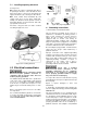
5.11 Installing/replacing abrasives See Figure 5-5. Disc: Clean disc surface of aluminum drive wheel. If replacing an abrasive, clean old adhesive from drive wheel with a solvent. Peel off backing and apply new abrasive (A), centering it on drive wheel. Belt: Push contact wheel backward (B) and engage catch (C) to lock in place. Install belt, making sure directional arrows printed on back of belt match direction of belt movement. Pull catch (C) upward to tension belt.
in Canada. The green-colored rigid ear, lug, and the like, extending from the adapter must be connected to a permanent ground such as a properly grounded outlet box. 3. 3. Grounded, cord-connected tools intended for use on a supply circuit having a nominal rating between 150 - 250 volts, inclusive: 7.0 Operation A bench grinder is designed for hand-grinding operations such as sharpening chisels, screwdrivers, drill bits, removing excess metal, and smoothing and polishing metal surfaces.
8.0 Adjustments 8.1 Eye Shield Tilt Adjustment 1. Loosen lock knob (A1, Figure 10). 2. Adjust eye shield (A2) to desired tilt angle. 3. Tighten lock knob (A1). Figure 7-1: safety key 7.2 Precautions 7.2.1 Wheel grinding 1. Before starting grinder, turn grinding wheel by hand to verify that it is clear of obstruction and turns freely. The tool rest and spark guard should not touch the wheel. 2. Keep tool rest and spark guard to within 1/16" of grinding wheel. 3.
If belt refuses to track properly, the rubber contact wheel must be adjusted parallel to drive wheel, as follows: 1. Loop a piece of string through the grinding wheel hole and suspend the wheel by holding up the string. 1. If belt wanders away from grinder, loosen top bolt (E, Figure 8-2) and tap top of cam plate (F) away from grinder. 2. Tap the wheel with a piece of scrap wood or a wooden dowel. 3. 2. If belt wanders toward grinder, loosen top bolt (E) and tap top of cam plate (F) toward grinder.
5. Unscrew arbor nut (C) with wrench. NOTE: Left-hand threads; turn nut clockwise to loosen. 6. Remove outer flange (D), wheel (E), and inner flange. of the current layer of abrasive to expose a fresh surface. A wheel dresser is also used to “true” a wheel; that is, to make the grinding surface parallel to the tool rest, so the entire wheel face presents an even surface to the work piece.
2. Turn on grinder and allow it to reach operating speed. 9.7 Cleaning 3. Set wheel dresser on tool rest and bring it into contact with wheel by raising its handle. Hold the dresser firmly. Metal shavings may still be hot from recent grinding operations. Make sure shavings and debris are cold before cleaning the grinder. Note: If sparks appear, increase the pressure of the dresser discs against the wheel. 4.
10.0 Troubleshooting JIGM-8 Grinder with Multitool Table 4 Symptom Possible Cause Correction * Motor will not start. Not connected to power source. Verify that plug is properly inserted into receptacle. Switch in Off position. Make sure safety key is inserted. Motor cord cut or abraded. Replace with new cord. Wheel cannot rotate because of obstruction. Unplug and turn grinding wheel by hand to ensure free movement. Restart. Plug on cord is faulty. Replace with new plug. Low line voltage.
Symptom Possible Cause Correction * Motor slows. Motor overloaded. Reduce load on motor; do not press so hard when grinding. Low line voltage. Check power line for proper voltage. Loose connections. Inspect connections. Motor overloaded. Reduce load on motor; do not press so hard when grinding. Electrical circuit overload; too many machines running on same circuit. Turn off other machines and try again. Incorrect fuse or circuit breaker. Have electrician upgrade service to outlet.
11.0 Optional accessories These accessory items, purchased separately, are available for your JET bench grinder. Contact your dealer to order, or call JET at the phone number on the cover.
12.1.
12.1.2 JIGM-8 Grinder with Multitool – Parts List Index No Part No Description Size Qty 1 ................ IBG8-01 ..................... Truss Head Screw ................................................... 3/16"-24 x 1/4" .............. 4 2 ................ IBG8-02 ..................... Rubber Pad ............................................................. ...................................... 4 3 ................ IBG8-03 ..................... Base Plate ..............................................
MultiTool Attachment: .................. 577115 ...................... Rubber Contact Wheel (not shown) ........................ 2” x 3-1/2” ..................... 1 For other replacement parts on the Mulitool attachment, contact Multitool at 800-660-0880. 13.
14.0 Warranty and Service JET® warrants every product it sells against manufacturers’ defects. If one of our tools needs service or repair, please contact Technical Service by calling 1-800-274-6846, 8AM to 5PM CST, Monday through Friday. Warranty Period The general warranty lasts for the time period specified in the literature included with your product or on the official JET branded website. • JET products carry a limited warranty which varies in duration based upon the product.
This page intentionally left blank.
427 New Sanford Road LaVergne, Tennessee 37086 Phone: 800-274-6848 www.jettools.