This .pdf document is bookmarked Operating Instructions and Parts Manual IBG Series Industrial Grinders Models IBG-8, IBG-10, IBG-12 JET 427 New Sanford Road LaVergne, Tennessee 37086 Ph.: 800-274-6848 www.jettools.com Part No.
1.0 Warranty and Service JET® warrants every product it sells against manufacturers’ defects. If one of our tools needs service or repair, please contact Technical Service by calling 1-800-274-6846, 8AM to 5PM CST, Monday through Friday. Warranty Period The general warranty lasts for the time period specified in the literature included with your product or on the official JET branded website. • JET products carry a limited warranty which varies in duration based upon the product.
2.0 Table of contents Section Page 1.0 Warranty and Service ..................................................................................................................................... 2 2.0 Table of contents............................................................................................................................................ 3 3.0 Safety warnings...................................................................................................................................
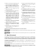
12. Do not operate this machine while tired or under the influence of drugs, alcohol or any medication. 13. Make certain the switch is in the OFF position before connecting the machine to the power supply. 3.0 Safety warnings 14. Make certain the machine is properly grounded. 1. Read and understand the entire owner's manual before attempting assembly or operation. 2. Read and understand the warnings posted on the machine and in this manual.
29. Remove loose items and unnecessary work pieces from the area before starting the grinder. 37. Direction of feed. Feed work into a blade or cutter against the direction of rotation of the blade or cutter only. 30. Don’t use in dangerous environment. Don’t use power tools in damp or wet location, or expose them to rain. Don’t use this grinder in a flammable environment. Keep work area well lighted. 38. Do not overtighten wheel nut. 39. Frequently clean grinding dust from beneath grinder. 40.
5.0 Specifications Model .................................................................. IBG-8 .................................. IBG-10 .................................. IBG-12 Stock Number .................................................... 578008 .................................. 578010 .................................. 578012 Motor and electricals: Motor type................................................................. induction, capacitor start, centrifugal switch ..........................
Dust/swarf collection: Dust port outside diameter ................. 2-1/2” (63.5mm) ..................... 2-1/2” (63.5mm) ..................... 2-1/2” (63.5mm) Recommended min. extraction volume......... 350 CFM ............................... 350 CFM ............................... 350 CFM Weights: Net.................................................... 64 lb (29.20 kg) ....................113 lb (51.50 kg) ........................ 176 lb (80 kg) Shipping............................................
6.0 Setup and assembly 6.1 Unpacking Separate all parts from the packing material. Check each part against sect. 6.2, Carton contents, and make certain that all items are accounted for before discarding any packing material. (Check grinder first to verify if any parts have been premounted.) 6.2 Carton contents Refer to Figure 4.
washers (L), through the tool rest (M), into the wheel housing. 6.5 Assembling eye shield brackets to spark guards Refer to Figure 5. Note: Spark guards (A) and eye shield brackets (D) are marked L for left side assembly and R for right side assembly. 1. Assemble the left spark guard and eye shield bracket using Figure 1 as a guide. Make sure spark guard and bracket are both marked L. 2. Install the right assembly in the same manner. 3. Install the right tool rest in the same manner. 4.
7.0 Electrical connections Check with a qualified electrician or service personnel if the grounding instructions are not completely understood, or if in doubt as to whether the tool is properly grounded. Failure to comply may cause serious or fatal injury. Electrical connections should be made by a qualified electrician in compliance with all relevant codes. This tool must be properly grounded.
Table 1 shows the correct size to use depending on cord length and nameplate ampere rating. If in doubt, use the next heavier gage. The smaller the gage number (AWG), the heavier the cord. Ampere Rating On all models, when the stop button is pushed, the wheels may take a few moments to completely stop. Note: After extended operation, housing may be warm to the touch.
9.0 Adjustments 9.1 Eye Shield Tilt Adjustment 1. Loosen lock knob (A1, Figure 10). 2. Adjust eye shield (A2) to the desired tilt angle. 1. Loop a piece of string through the grinding wheel hole and suspend the wheel by holding up the string. 2. Tap the wheel with a piece of scrap wood or a wooden dowel. 3. A good wheel will "ring"; a defective wheel will "thud". Discard any wheel that does not "ring". An internal defect may not be apparent by visual inspection alone.
4. 10.4.1 Adjusting concentricity Stabilize wheel by holding opposite wheel firmly, or placing a wood wedge between wheel and tool rest. If the outside face is not rotating concentric to arbor, try shifting the wheel closer to arbor centerline before tightening the nut. Another method of achieving concentricity is the use of a wheel dresser. “Dressing” is the removal of the current layer of abrasive to expose a fresh surface.
10.5 Dressing the wheels 10.6 Wire wheel brushes Below is a general procedure for dressing a grinding wheel. Always consult the wheel dresser manufacturer’s instructions for specific information pertaining to the tool. Wire brushing provides a fast way to remove rust scale, burrs, and paint from metal. Use coarse wire brushes for hard cleaning jobs. Use fine wire brushes for polishing and finish work. When the brush tips become dull, reverse the brush on the grinder.
11.0 Troubleshooting the IBG series Bench Grinders Table 3 Symptom Possible Cause Correction Motor will not start. Not connected to power source. Verify that plug is properly inserted into receptacle. Switch in Off position. Make sure safety key is inserted. Motor cord cut or abraded. Replace with new cord. Wheels cannot rotate because of obstruction. Unplug and turn grinding wheel by hand to ensure free movement. Restart. Plug on cord is faulty. Replace with new plug. Low line voltage.
Symptom Possible Cause Correction Motor slows. Motor overloaded. Reduce load to motor; do not press so hard. Low line voltage. Check power line for proper voltage. Loose connections. Inspect connections. Motor overload. Reduce load to motor; do not press so hard. Electrical circuit overload; too many electrical machines running on same circuit. Turn off other machines and try again. Incorrect fuse or circuit breaker Have electrician upgrade service to outlet.
12.0 Optional accessories These accessory items, purchased separately, are available for your JET bench grinder. Contact your dealer to order, or call JET at the phone number on the cover. 578172 Stand for Grinders 578173 Deluxe Stand for Grinders 578100 Flexible LED Lamp (3W) 13.0 Replacement Parts Replacement parts are listed on the following pages. To order parts or reach our service department, call 1800-274-6848 Monday through Friday, 8:00 a.m. to 5:00 p.m. CST.
13.1.
13.1.2 IBG-8 Grinder – Parts List Index No Part No Description Size Qty 1 ................ IBG8-01 ..................... Truss Head Screw ................................................... 3/16”-24 x 1/4”............... 4 2 ................ IBG8-02 ..................... Rubber Pad.............................................................. ...................................... 4 3 ................ IBG8-03 ..................... Base Plate ..............................................................
Index No Part No Description Size Qty 54-7 ........... IBG8-54-7.................. Square Nut............................................................... M6 ................................. 1 55 .............. TS-0680041 .............. Flat Washer ............................................................. 3/8” ................................ 2 56 .............. TS-0060011 .............. Hex Cap Screw ........................................................ 3/8”-16 x 1/2”................. 2 57 ..
13.2.
13.2.2 IBG-10 Grinder – Parts List Index No Part No Description Size Qty 1 ................ IBG8-01 ..................... Truss Head Screw ................................................... 3/16”-24 x 1/4”............... 4 2 ................ IBG10-02 ................... Rubber Pad.............................................................. ...................................... 4 3 ................ IBG10-03 ................... Base Plate ...............................................................
Index No Part No Description Size Qty 55 .............. TS-0680041 .............. Flat Washer ............................................................. 3/8” ................................ 2 56 .............. TS-0060011 .............. Hex Cap Screw ........................................................ 3/8”-16 x 1/2”................. 2 57 .............. IBG8-33 ..................... Eye Shield ............................................................... ......................................
13.3.
13.3.2 IBG-12 Grinder – Parts List Index No Part No Description Size Qty 1 ................ IBG8-04 ..................... Truss Head Screw ................................................... 3/16”-24 x 3/8”............. 13 2 ................ IBG10-03 ................... Base Plate ............................................................... ...................................... 1 3 ................ IBG12-03 ................... Start Capacitor .........................................................
Index No Part No Description Size Qty 54-7 ........... IBG8-54-7.................. Square Nut............................................................... M6 ................................. 1 55 .............. TS-0680041 .............. Flat Washer ............................................................. 3/8” ................................ 2 56 .............. TS-0060011 .............. Hex Cap Screw ........................................................ 3/8”-16 x 1/2”................. 2 57 ..
13.4.1 IBG-Stand Assembly (OPTIONAL) – Exploded View 13.4.2 IBG-Stand Assembly (OPTIONAL) – Parts List Index No. Part No. Description Size Qty .................. 578172 ...................... IBG-Stand for Bench Grinders (#1 thru 13) ............. ...................................... 1 1 ................ IBGS-01 .................... Base......................................................................... ...................................... 1 2 ................ IBGS-02 ....................
13.5.1 DBG-Stand Assembly (OPTIONAL) – Exploded View 13.5.2 DBG-Stand Assembly (OPTIONAL) – Parts List Index No. Part No. Description Size Qty .................. 578173 ...................... DBG-Stand for Bench Grinders (#1 thru 14)............ ...................................... 1 1 ................ DBGS-01 ................... Platform ................................................................... ...................................... 1 2 ................ DBGS-02 ...................
14.0 Electrical Connections 14.
14.
14.
427 New Sanford Road LaVergne, Tennessee 37086 Phone: 800-274-6848 www.jettools.