This .pdf document is bookmarked Operating Instructions and Parts Manual 12" Variable Speed Drill Press Model: JWDP-12 JET 427 New Sanford Road LaVergne, Tennessee 37086 Ph.: 800-274-6848 www.jettools.com Part No.
14. Do not operate this machine while tired or under the influence of drugs, alcohol or any medication. 1.0 IMPORTANT SAFETY INSTRUCTIONS WARNING – To reduce risk of injury: 1. Read and understand the entire owner’s manual before attempting assembly or operation. 2. Read and understand the warnings posted on the machine and in this manual. Failure to comply with all of these warnings may cause serious injury. 3. Replace the warning labels if they become obscured or removed. 4.
1. Maintain tools with care. Keep drill bits sharp and clean for the best and safest performance. Follow instructions for lubricating and changing accessories. 35. Do not stand on the machine. Serious injury could occur if the machine tips over. 36. Never leave the machine running unattended. Turn the power off and do not leave the machine until it comes to a complete stop. 32. Disconnect tools before servicing; when changing accessories, such as blades, bits, cutters and the like. 37.
3.0 Table of contents 1.0 IMPORTANT SAFETY INSTRUCTIONS ....................................................................................................... 2 2.0 About this manual ......................................................................................................................................... 3 3.0 Table of contents .......................................................................................................................................... 4 4.0 Specifications.......
4.0 Specifications Model Number ......................................................................................................................................... JWDP-12 Stock Number ............................................................................................................................................. 716000 Swing .............................................................................................................................................. 12 in. (305mm) Type ...
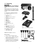
5.0 Unpacking Read and understand all assembly instructions before attempting assembly. Failure to comply may cause serious injury. Separate all parts from the packing material. Check each part against sect. 5.1, Contents of shipping container and make certain that all items are accounted for before discarding any packing material. 5.1 Contents of shipping container Refer to Figures 1 and 2.
6.0 Assembly 6.1 Base and column assembly Refer to Figure 3: 1. Place base (D) on a level floor. 2. Place column assembly (E) on base (D) and align holes in column support with holes in base. 3. Using a 5/8-in wrench, secure column (E) with four M10 x 25 hex cap screws (N) to the base. 6.2 Table and rack Refer to Figure 4: Note: If table arm/support assembly (C) and rack (E3) are already installed on column (E), proceed to step 4. Otherwise, begin with step 1. 1.
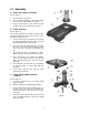
6.4 Mounting the head 1. With the aid of a second person, carefully lift head onto column top (Figure 5). The head assembly is heavy. To avoid injury and/or damage to equipment, lift head onto column only with additional assistance. 2. Rotate head assembly until sides of belt cover (A1) are parallel with sides of base (D, Figure 3). 3. Tighten two set screws (A2, Figure 5) with a 5mm wrench until they are snug. 6.
7.0 Electrical connections Use only 3-wire extension cords that have 3-prong grounding plugs and 3-pole receptacles that accept the tool's plug. All electrical connections must be done by a qualified electrician in compliance with all local codes and ordinances. Failure to comply may result in serious injury. Repair or replace immediately. The JWDP-12 is rated at 115-volt power.
8.0 Adjustments 8.1 Removing chuck and arbor Refer to Figure 8: 1. Unplug machine from power source. 2. Raise table until it is about seven inches below chuck. 3. Place a piece of scrap wood on the table, and lower quill (E) using the downfeed handle (A). 4. Still maintaining the lowered quill position, rotate spindle to align key hole in spindle with key hole in quill (E). 5. Insert drift key (D) into the aligned slots and tap lightly. The chuck and arbor assembly should fall from the spindle.
8.4 Return spring adjustment The return spring is located opposite the downfeed handle hub and sets the tension for the downfeed handle. It is adjusted at the factory and should not need further adjustment. If adjustment is deemed necessary: 1. Unplug machine from power source. Refer to Figure 10: 2. Loosen jam nut (A) and hex nut (B). Do not remove. 3. Pull out slightly the coil spring cover (C) while firmly holding it.
Figure 12 11.0 Basic operation 9.0 Features and controls Always use a back-up piece of scrap wood to cover the table. This protects both the table and the drill bit. Refer to Figure 12: Downfeed Handle – Lower and raise spindle. Place material to be drilled in such as way as to come into contact with the left side of the column. This prevents the material from spinning. Lamp Switch – Turns lamp on and off. Laser Switch – Turns laser on and off.
12.0 Troubleshooting JWDP-12 Drill Press Symptom Possible Cause Correction * Drill press unplugged from wall or Check all plug connections. motor. Drill press will not start. Fuse blown or circuit breaker tripped. Replace fuse or reset circuit breaker. Cord damaged. Replace cord. Starting capacitor bad. Replace starting capacitor. Drill press does not come Extension cord too light or too long. up to speed. Low current. Drill Press vibrates excessively. Noisy Operation. Workpiece Burns.
13.0 Replacement parts 13.1.
13.1.2 JWDP-12 Drill Press – Parts List To order parts or reach our service department, call 1-800-274-6848 Monday through Friday, 8:00 a.m. to 5:00 p.m. CST. Having the Model Number and Serial Number of your machine available when you call will allow us to serve you quickly and accurately. Index No Part No Description Size Qty 1 ................ JWDP12-001 ............. Base......................................................................... ...................................... 1 201 ..........
Index No Part No Description Size Qty 50 .............. JWDP12-050 ............. Drift Key ................................................................... ...................................... 1 51 .............. JWDP12-051 ............. Chuck Arbor ............................................................. ...................................... 1 207 ............ JWDP12-207 ............. Chuck Assembly (#52 and 53)................................. ...................................... 1 52 ...
Index No Part No Description Size Qty 105 ............ TS-1540061 .............. Hex Nut .................................................................... M8 ................................. 5 106 ............ JWDP12-106 ............. Phillips Screw ........................................................ M5x8 ............................. 2 107 ............ TS-2193051 .............. Internal Tooth Lock Washer..................................... 5mm .............................. 2 108 ............
14.
15.0 Warranty and Service JET warrants every product it sells against manufacturers’ defects. If one of our tools needs service or repair, please contact Technical Service by calling 1-800-274-6846, 8AM to 5PM CST, Monday through Friday. Warranty Period The general warranty lasts for the time period specified in the literature included with your product or on the official JET branded website. • JET products carry a limited warranty which varies in duration based upon the product.
427 New Sanford Road LaVergne, Tennessee 37086 Phone: 800-274-6848 www.jettools.