
Use and Care Manual

25
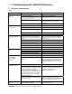
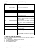
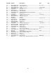
11.2 DRO messages and fault codes (JWL-1840DVR only)
Table 3
Display Possible Cause Correction
RSET Significant load spike due
to chisel dig-in; or fwd/rev
switch moved while in
education mode
To clear, turn off switch, wait for two “beeps”, then turn on
switch.
Refer to sect. 11.3 to analyze motor load.
Alarm code Message Explanation
Er00 Unexpected fault Problem with main circuit board hardware.
Er01 SRM not Rotate Five attempts to start motor were unsuccessful.
Er02 RPS State Error 0 Problem with rotor position sensor (RPS) circuit. Possible
dust accumulation on RPS circuit, or defective sensor
components
Er03 RPS State Error 1 Problem with rotor position sensor (RPS) circuit. Requires
inspection by qualified personnel.
Er04 Hardware Fault Problem with IGBT (power circuit) section of control board,
which activates motor. Possible causes: at least one motor
phase current has reached critical value; or IGBT
components are damaged. This fault may also be caused by
inverter section or DC bus.
Er05 Unexpected Software Trap Indicates possible bug in controller software. Cycle power to
the unit to clear.
Er13 Low Voltage Voltage of internal DC bus on main control board is below
allowable threshold. This fault may also display when power
is turned off.
Er14 PFC Fault Problem with power factor correction unit. Repair is advised
by qualified personnel.
Er50 Overheat Heatsink temperature exceeds allowable threshold.
Er55 EEPROM Data Fault Problem with main board EEPROM. Also occurs if main
board has been factory reset, powered off, then turned on
again. Power down completely, then restart unit to re-
establish factory defaults.
Er56 EEPROM Work Fault EEPROM on main board not responding; may be missing,
broken, or tracks damaged.
dISC Disconnected Communication failure between HMI board and main control
board.
L.SPd Low speed Controller receiving signal that rotor is not turning. Probable
cause – motor windings not properly energized to turn rotor,
caused by loose connection in 6-pin motor winding cable.
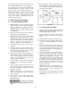
11.3 Motor load display (JWL-1840DVR only)
To enter motor load display for troubleshooting purposes, proceed as follows. This can be done with lathe in
normal or educational mode.
1. Press and hold speed knob until display flashes, then release knob.
2. Slowly rotate knob clockwise for 5 detents.
3. Rotate counterclockwise for 3 detents.
4. Rotate clockwise for 2 detents.
5. Press knob 5 times.
6. The readout will display “Load.” Turn on lathe and readout will now display motor load instead of speed.
Load is shown as a percentage of the power capacity of the controller.
7. Cycling power to the lathe will revert back to displaying speed.