Operating Instructions and Parts Manual 50-inch Electrical Slip Roll Machine Model ESR-1650T WALTER MEIER (Manufacturing) Inc. 427 New Sanford Road LaVergne, Tennessee 37086 Ph.: 800-274-6848 www.waltermeier.com Part No. M-756027 Revision A2 12/2011 Copyright © 2011 Walter Meier (Manufacturing), Inc.
Warranty and Service Walter Meier (Manufacturing) Inc., warrants every product it sells. If one of our tools needs service or repair, one of our Authorized Service Centers located throughout the United States can give you quick service. In most cases, any of these Walter Meier Authorized Service Centers can authorize warranty repair, assist you in obtaining parts, or perform routine maintenance and major repair on your JET® tools.
Table of Contents Warranty and Service .............................................................................................................................. 2 Table of Contents .................................................................................................................................... 3 Warnings ................................................................................................................................................. 4 Introduction .....................
Warnings 1. Read and understand the entire owner’s manual before attempting assembly or operation. 2. Read and understand the warnings posted on the machine and in this manual. Failure to comply with all of these warnings may cause serious injury. 3. Replace the warning labels if they become obscured or removed. 4. This powered slip roll machine is designed and intended for use by properly trained and experienced personnel only.
21. Keep visitors a safe distance from the work area. Keep children away. 22. Make your workshop child proof with padlocks, master switches or by removing starter keys. 23. Give your work undivided attention. Looking around, carrying on a conversation and “horse-play” are careless acts that can result in serious injury. 24. Do not overreach. Failure to maintain proper working position can cause you to fall into the machine or allow clothing to get caught, pulling you into the machine. 25.
Specifications Model ................................................................ESR-1650T-1 ............................................. ESR-1650T-3 Stock Number............................................................. 756027 ...................................................... 756028 Construction: Frame ................................................................... cast iron ..................................................... cast iron Rolls .........................................
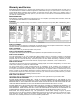
Features and Terminology Figure 1 - Features Floor mounting holes Figure 2 – Hole centers 7
2. On the transformer, remove the wire terminal from the 230V contact and connect to the 460V contact. Unpacking Open shipping container and check for shipping damage. Report any damage immediately to your distributor and shipping agent. Do not discard any shipping material until the Slip Roll is assembled and running properly. 3. On the thermal relay, make sure the dial is set to the proper amperage. 4. If using a plug, install a proper 460V, ULlisted plug.
The stationary, or top, roll is secured at its left end to the gear side of the machine with the cap screw and jam nut (see Figure 1). These can be adjusted if needed. Foot Pedal Operation The shrouded foot control has pedals for instant forward or reverse motion. Push the emergency stop button for fast shut down of the slip roller. To re-start the machine, rotate the emergency stop button clockwise until it releases. Figure 2 Forming a Radius 1. Adjust the pinch roll as needed.
3. To remove the tube from the stationary roll, pull the sleeve outward until it clears the end bracket; then pivot the roll outward, as shown in Figure 5. 4. After the tube is removed, reposition the stationary roll, making sure the sleeve is pushed back in completely, as shown in Figure 5. Figure 6 Maintenance 1. Keep the rolls clean and rust-free, and periodically apply a light film of oil. Figure 5 2. Place a few drops of 30W oil into the holes at each end of the rolls (see Figure 6).
Replacement Parts To order parts or reach our service department, call 1-800-274-6848, Monday through Friday (see our website for business hours, www.waltermeier.com). Having the Model Number and Serial Number of your machine available when you call will allow us to serve you quickly and accurately.
Parts List for ESR-1650T Index No Part No Description Size Qty 1............... ESR1650T-1 ............... Side Cover ......................................................................................... 1 2............... ESR1650T-2 ............... Electric Box ........................................................................................ 1 2-1............ ESR1650T-2-1 ............ Short & Overload Protection ............................W1A............................ 1 2-2............
Index No Part No Description Size Qty 18-14 ........ ESR1650T-18-14 ........ Housing .............................................................................................. 1 18-15 ........ ESR1650T-18-15 ........ Oil Seal ...........................................................Φ50XΦ35X7 mm ........ 1 18-16 ........ ESR1650T-18-16 ........ Key .................................................................8x25 mm .................... 1 18-17 ........ ESR1650T-18-17 ........ Output Shaft ....
Index No Part No Description Size Qty 57 ............. TS-2246162 ................ Socket Head Button Screw ..............................M6X16........................ 5 58 ............. TS-1505051 ................ Socket Head Cap Screw..................................M10x35 ...................... 4 59 ............. ESR1650T-59 ............. Connecting Bushing ........................................................................... 2 60 ............. ESR1650T-60 ............. Fixing Screw...........
KM1 KM4 L1 FR L 15 KM2 MAIN MOTOR M N1 N 1.5mm KM3 TC 0.75mm KM4 QF 0 AC24V 1 EL1 14 TA1 2 4 13 KM1 SQ1 EL2 FR 5 KM2 6 SB2 7 KM4 8 SB1 KM2 KM1 11 9 JK1 KM4 FR: HEAT RELAY KM1/2/3: CONTACTOR QF: BREAKER SWITCH SQ1: INTERLOCKNG SWITCH TA: E.S.
KM1 KM4 L1 FR L 16 KM2 MAIN MOTOR M N1 N 1.5mm KM3 TC 0.75mm KM4 QF 0 AC24V 1 EL1 14 TA1 2 4 13 KM1 SQ1 EL2 FR 5 KM2 6 SB2 7 KM4 8 SB1 KM2 KM1 11 9 JK1 KM4 FR: HEAT RELAY KM1/2/3/4: CONTACTOR QF: BREAKER SWITCH SQ1: INTERLOCKNG SWITCH TA: E.S.