This .pdf document is bookmarked Operating Instructions and Parts Manual Geared Head Lathe 14x40 inch Model GH-1440 JET 427 New Sanford Road LaVergne, Tennessee 37086 Ph.: 800-274-6848 www.jettools.com Part No.
is recommended. Wear protective hair covering to contain long hair. Do not wear any type of glove. 1.0 IMPORTANT SAFETY INSTRUCTIONS 15. Always wear ANSI Z87.1 approved safety glasses or face shield while using this machine. (Everyday eyeglasses only have impact resistant lenses; they are not safety glasses.) Read and understand the entire owner's manual before attempting set-up or operation of this lathe. 16. Do not overreach. Keep proper footing and balance at all times.
3. Never leave the machine running unattended. Turn the power off and do not leave the machine until moving parts come to a complete stop. 35. Do not operate the lathe in flammable or explosive environments. Do not use in a damp environment or expose to rain. 34. Remove loose items and unnecessary work pieces from the area before starting the machine.
2.0 Table of contents Section Page 1.0 IMPORTANT SAFETY INSTRUCTIONS ....................................................................................................... 2 2.0 Table of contents ............................................................................................................................................ 4 3.0 About this manual .......................................................................................................................................... 5 4.
14.12.1 Stand and Brake Assembly – Exploded View ................................................................................... 50 14.12.2 Stand and Brake Assembly – Parts List ............................................................................................ 51 14.13.1 End Gear Assembly – Exploded View............................................................................................... 52 14.13.2 End Gear Assembly – Parts List .......................................................
4.
GH-1440-1 Tailstock Tailstock spindle travel Diameter of tailstock spindle Taper in tailstock spindle Main materials Headstock Bed Apron/Saddle Tailstock Splash guard Stand Dimensions Bed width Bed length Height of bed from floor Overall dimensions, L x W x H Shipping dimensions, L x W x H Weights Net weight, approx. Shipping weight, approx. GH-1440-3 4-3/4 in. (121 mm) 1-3/4 in. (45 mm) MT3 Cast iron Cast iron Cast iron Cast iron Steel Steel 10-3/16 in. (259 mm) 54-1/2 in. (1384 mm) 12-3/4 in.
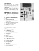
5.0 Uncrating Open shipping crate and check for shipping damage. Report any damage immediately to your distributor and shipping agent. Do not discard any shipping material until the Lathe is assembled and running properly. Compare the contents of your crate with the following parts list to make sure all parts are intact. Missing parts, if any, should be reported to your distributor. Read and understand the entire contents of this manual before attempting set-up or operation.
6.0 Installation 1. Finish removing the wooden crate from around the lathe. 2. Unbolt the lathe from the shipping crate bottom. 3. Choose a location for the lathe that is dry, has good lighting, and has enough room to service the lathe on all four sides 4. Place two steel rods or pipes (of sufficient strength) into four holes (A, Fig. 2) of lathe stand. Sling the lathe with properly rated straps. Do not lift by spindle.
4. Cover all chuck jaws and scroll inside the chuck with Mobilith® AW2. Cover the spindle, cam locks, and chuck body with a light film of Mobil DTE® Oil Heavy Medium. 5. Lift the chuck up to the spindle nose and press onto the spindle. Tighten in place by turning the cam locks 1/4 turn clockwise. The index mark (A, Fig. 3) on the camlock should be between the two indicator arrows (B, Fig. 3).
3. Apron – Oil must be up to indicator mark in oil sight glass (A, Fig. 7). Top off with Mobil DTE® Oil Heavy Medium. Remove oil cap (B, Fig. 7) on top of apron to fill. To drain, remove drain plug on bottom of apron. Drain oil completely and refill after the first month of operation. Then, change oil in the apron annually. 4. Leadscrew Feed Rod – Lubricate ball oiler (A, Fig. 8) on leadscrew/feed rod bracket with Mobil DTE® Oil Heavy Medium once daily. 5. Tailstock – Lubricate two ball oilers (B, Fig.
8.0 Coolant preparation Follow coolant manufacturer’s recommendations for use, care and disposal. 1. Remove rear access cover on tailstock end. Make sure coolant tank has not shifted during transport and is located properly under the recovery chute (Fig. 10). 2. Pour three gallons of coolant mix into drip pan. 3. After machine has been connected to power, turn on coolant pump and check to see coolant is cycling properly. 4. Fasten coolant door to stand. Figure 10 9.
10.0 General description Lathe bed The lathe bed (A, Fig. 11) is made of high grade cast iron. By combining high cheeks with strong cross ribs, a bed with low vibration and high rigidity is realized. Two precision ground v-slideways, reinforced by heat hardening and grinding, are an accurate guide for the carriage and headstock. The main drive motor is mounted in the stand below headstock. Headstock The headstock (B, Fig. 11) is cast from high grade, low vibration cast iron.
Gear box The gear box (D, Fig. 13) is made from high quality cast iron and is mounted to the left side of the machine bed. Steady rest The steady rest (E, Fig. 13) serves as a support for shafts on the free tailstock end. The steady rest is mounted on the bedway and secured from below with a bolt, nut and locking plate. The sliding fingers require continuous lubrication at the contact points with the workpiece to prevent premature wear. To set the steady rest: 1. Loosen three hex socket screws. 2.
2. Headstock Gear Change Levers (E, Fig. 14) – located on front of headstock. Move levers according to speed chart for desired setting. 3. Leadscrew/Feed Rod Directional Lever (F, Fig. 14) – located on front of headstock. Moving the lever up causes carriage travel toward the tailstock; moving the lever down causes carriage travel toward the headstock (when chuck is spinning in forward or counterclockwise direction). Do not move lever while machine is running. 4. Feed/Lead Selector Lever (G, Fig.
12. Half Nut Engage Lever (thread cutting) (F, Fig. 15) – located on front of the apron. Move the lever down to engage. Move the lever up to disengage. 13. Cross Traverse Handwheel (G, Fig. 15) – located above the apron assembly. Rotate clockwise or counter-clockwise to move, or position. 14. Compound Rest Traverse Handwheel (H, Fig. 15) – located on the end of the compound slide. Rotate clockwise or counterclockwise to move, or position. 15. Tool Post Clamping Lever (J, Fig.
11.2 Feed and thread selection 1. Refer to the feed and thread charts found on the gear box faceplate (A, Fig. 18 and sect. 13.0 of this manual). 2. Move levers (B, C, D, E, F, Fig. 18) to the appropriate positions according to the chart. 11.3 Change gears replacement The 25T, 127T, 50T gears are installed in the end gear compartment when delivered from the factory. This combination will cover most inch feeds and threads under normal circumstances.
11.5 Powered carriage travel 1. Push lever (B, Fig. 20) to the left and down to engage crossfeed. 2. Pull lever to the right and up to engage longitudinal feed. 11.6 Thread cutting 1. Set forward/reverse lever (A, Fig. 20) up or down depending on the desired direction. 2. Set selector levers (A, B, C, D, Fig. 21) to desired rate. Note: For threading, lever (D) will be set at "C" or "E", depending on desired thread. 3. Push lever (B, Fig. 19) to the right. 4. Engage the half nut lever (C, Fig.
5. Move the carriage again and readjust if necessary. Note: Over-adjustment will cause excessive and premature wear of the gibs. 12.2 Cross slide If the cross slide is too loose, follow procedure below to tighten: 1. Loosen the rear gib screw (not shown) approximately one turn. 2. Tighten the front gib screw (B, Fig. 23) a quarter turn. Turn the cross slide handwheel to see if the cross slide is still loose. If it is still loose, tighten the front screw a bit more and try again. 3.
12.7 Headstock alignment The headstock has been aligned at the factory and should not require adjustment. However, if adjustment is deemed necessary, follow the procedure below to align the headstock: 1. Using a machinist's precision level on the bedways, make sure the lathe is level side to side and front to back. If the lathe is not level, correct to a level condition before proceeding. Re-test alignment if any leveling adjustments were made. 2.
12.10 Belt replacement and adjustment 1. Disconnect machine source (unplug). from the power 2. Open the end gear cover and lower cover on the headstock side. 3. Take tension off old belts by loosening motor mount hex nut (A, Fig. 27). 4. Remove belts. Install new belts onto pulleys. 5. Tension by tightening motor mount hex nut until 8 lbs. force causes approximately 3/4" deflection on belts. 6. Close end gear door, install cover and connect lathe to the power source. 12.
13.0 Operation tables 13.1 Thread table 13.2 Feed table 14.0 Replacement Parts Replacement parts are listed on the following pages. To order parts or reach our service department, call 1800-274-6848 Monday through Friday, 8:00 a.m. to 5:00 p.m. CST. Having the Model Number and Serial Number of your machine available when you call will allow us to serve you quickly and accurately. Non-proprietary parts, such as fasteners, can be found at local hardware stores, or may be ordered from JET.
14.1.
14.1.2 Headstock Assembly I – Parts List Index No. Part No. Description Size Qty 1 ................ C6136-02755 ............ Plug.......................................................................... ...................................... 1 2 ................ GH1440K-02119 ....... Headstock Cover ..................................................... ...................................... 1 3 ................ TS-1503061 .............. Hex Socket Hd Cap Screw ......................................
Index No. Part No. Description Size Qty 142 ............ GH1440K-142 ........... O-Ring ..................................................................... 25x2.65 mm .................. 3 159 ............ TS-1506041 .............. Hex Socket Hd Cap Screw ...................................... M12x35 ......................... 2 160 ............ GH1440K-02304-24 .. Name Plate .............................................................. ......................................
14.2.
14.2.2 Headstock Assembly II – Parts List Index No. Part No. Description Size Qty 61 .............. TS-1504031 .............. Hex Socket Hd Cap Screw ...................................... M8x16 ........................... 1 62 .............. 04-12 ......................... Washer .................................................................... ...................................... 1 63 .............. 04-11 ......................... Pulley ...........................................................
14.3.
14.3.2 Headstock Assembly III – Parts List Index No. Part No. Description Size Qty 56 .............. TS-150303 ................ Hex Socket Hd Cap Screw ...................................... M6x12 ......................... 18 61 .............. TS-1504031 .............. Hex Socket Hd Cap Screw ...................................... M8x16 ........................... 3 74 .............. F006050 .................... C-Retaining Ring, Ext .............................................. 25 mm .................
14.4.
14.4.2 Gearbox Assembly I – Parts List Index No. Part No. Description Size Qty 1 ................ 05-73 ......................... Plug.......................................................................... ...................................... 1 2 ................ GH1440K-05101 ....... Gearbox Casting ...................................................... ...................................... 1 3 ................ 05-07 ......................... Front Cover ..........................................
Index No. Part No. Description Size Qty 64 ............. GH1440K-05301-19 .. Name Plate .............................................................. ...................................... 1 65 .............. GB2672 ..................... Screw ....................................................................... M3x6 ............................. 6 66 ............. GH1440K-05303 ....... Graphic Plate - Speed Chart ................................... ......................................
14.5.
14.5.2 Gearbox Assembly II – Parts List Index No. Part No. Description Size Qty 1 ................ TS-1503041 .............. Hex Socket Cap Screw ............................................ M6x16 ........................... 1 2 ................ 05-42 ......................... Washer .................................................................... ...................................... 1 3 ................ 05-41 ......................... Gear .........................................................
Index No. Part No. Description Size Qty 58 .............. GH1440K-05705 ....... Shaft ........................................................................ ...................................... 1 59 .............. GH1440A-05307 ....... Shaft Collar .............................................................. ...................................... 1 60 .............. 05-18 ......................... Flange ...................................................................... .......................
14.6.
14.6.2 Apron Assembly I – Parts List Index No. Part No. Description Size Qty 1 ................ TS-1503021 .............. Hex Socket Hd Cap Screw ...................................... M6x10 ........................... 2 2 ................ 06-37 ......................... Half Nut .................................................................... ...................................... 1 3 ................ 06-36 ......................... Bracket...........................................................
14.7.
14.7.2 Apron Assembly II – Parts List Index No. Part No. Description Size Qty 36 .............. 06-44 ......................... Bushing .................................................................... ...................................... 1 37 .............. 06-43 ......................... Shaft ........................................................................ ...................................... 1 38 .............. F006044 .................... C-Retaining Ring, Ext .......................
14.8.
14.8.2 Saddle and Cross Slide Assembly – Parts List Index No. Part No. Description Size Qty 1 ................ GH1440K-04702 ....... Gib ........................................................................... ...................................... 1 2 ................ GH1440A-04728 ....... Gib Adjusting Screw ................................................ ...................................... 2 3 ................ TS-1533032 .............. Pan Head Machine Screw ...................................
Index No. Part No. Description Size Qty 65 .............. GHB1340A-04788 .... Pin............................................................................ ...................................... 1 66 .............. GHB1340A-04507 .... Sleeve ...................................................................... ...................................... 1 67 .............. GH1440K04303 ....... Plate......................................................................... ..................................
14.9.
14.9.2 Top Slide and Tool Post – Parts List Index No. Part No. Description Size Qty 1 ................ GH1440A-04707 ....... Tool Post.................................................................. ...................................... 1 2 ................ GB83-88 .................... Tool Lock Screw ...................................................... 10x50 mm ..................... 8 3 ................ C0632-04704 ............ Handle Hub ...........................................................
14.10.
14.10.2 Tailstock Assembly – Parts List Index No. Part No. Description Size Qty 1 ................ GH1440A-03703A ..... Index Ring ............................................................... ...................................... 1 2 ................ TS-1503051 .............. Hex Socket Hd Cap Screw ...................................... M6x20 ........................... 3 3 ................ GH1440K-03102 ....... Hub .......................................................................... ........
14.11.
14.11.2 Bed and Shaft Assembly – Parts List Index No. Part No. Description Size Qty 1 ................ GH1440K-01101 ....... Bed .......................................................................... ...................................... 1 2 ................ GH1440A-01704 ....... Rack (short) ............................................................. ...................................... 1 3 ................ TS-150306 ................ Hex Socket Cap Screw .......................................
Index No. Part No. Description Size Qty 58 .............. F010448 .................... Socket Set Screw DP .............................................. M8x16 ........................... 1 59 .............. C0632A-01504 .......... Shaft Box Cover....................................................... ...................................... 1 60 .............. TS-1502021 .............. Socket Head Cap Screw ......................................... M5x10 ...........................
14.12.
14.12.2 Stand and Brake Assembly – Parts List Index No. Part No. Description Size Qty 1 ................ GH1440K-01-707A.... Splash Guard ........................................................... M6x10 ........................... 1 2 ................ TS-1503021 .............. Hex Socket Hd Cap Screw ...................................... M6x10 ........................... 2 3 ................ TS-1550041 .............. Flat Washer ............................................................. 6 mm ......
14.13.
14.13.2 End Gear Assembly – Parts List Index No. Part No. Description Size Qty 1 ................ TS-1502041 .............. Hex Socket Hd Cap Screw ...................................... M5x16 ........................... 1 2 ................ GH1440K-1304 ......... Washer, spcl ............................................................ 6 mm ............................. 1 3 ................ 04-50 ......................... Gear .........................................................................
14.14.1 Follow Rest – Exploded View 14.14.2 Follow Rest – Parts List Index No. Part No. Description Size Qty .................. GH1440K-FRA .......... Follow Rest Assembly (#1 thru 10) .......................... ........................................ 1 ................ GH1440-09-02 .......... Knob ........................................................................ ...................................... 2 2 ................ TS-1523011 .............. Socket Set Screw ..............................
14.15.1 Thread Dial Assembly – Exploded View 14.15.2 Thread Dial Assembly – Parts List Index No. Part No. Description Size Qty .................. GH1440K-TDA .......... Thead Dial Assembly (includes #1 thru 9) ............... ........................................ 1 ................ 06-22 ......................... Dial........................................................................... ...................................... 1 2 ................ GB879-3x12 .............. Spring Pin ............
14.16.
14.16.2 Steady Rest – Parts List Index No. Part No. Description Size Qty .................. GH1440K-SRA .......... Steady Rest Assembly (#1 thru 21) ......................... ...................................... 1 1 ................ GH1440-09-02 .......... Knob ........................................................................ ...................................... 3 2 ................ TS-1523011 .............. Socket Set Screw .................................................... M6x6 ..........
14.17.1 Coolant and Work Light Assembly – Exploded View 14.17.2 Coolant and Work Light Assembly – Parts List Index No. Part No. Description Size Qty 1 ................ GHB1340-EL ............. Work Light................................................................ ...................................... 1 2 ................ TS-1503051 .............. Hex Socket Hd Cap Screw ...................................... M6x20 ........................... 3 3 ................ TS-1502051 ..............
14.18.1 Chuck Guard Assembly – Exploded View 14.18.2 Chuck Guard Assembly – Parts List Index No. Part No. Description Size Qty ................. GH1440K-CGA ......... Chuck Guard Assembly (#1 thru 19) ..................... .................................... 1 1 ............... GH1440K-19701J ...... Chuck Guard ......................................................... .................................... 1 2 ............... GHB1340A-19501E ... Guard Acrylic Window .....................................
14.19.1 Lead Screw Cover Assembly – Exploded View 14.19.2 Lead Screw Cover Assembly – Parts List Index No. Part No. Description Size Qty 1 ................ GH1440K-14701 ....... Left Flange ............................................................... ...................................... 1 2 ................ TS-1502031 .............. Hex Socket Hd Cap Screw ...................................... M5x12 ........................... 2 3 ................ LGB 28-900-70.......... Telescoping Sleeve ......
14.20.
14.20.2 Accessories I – Parts List Index No. Part No. Description Size Qty .................. GH1440-TBCP .......... Tool Box Complete (#1 thru 28)............................... ...................................... 1 1 ................ .................................. Tool Box................................................................... ...................................... 1 2 ................ GH1440-0611............ Handle Sleeve ......................................................... ..
14.21.1 Accessories II – Exploded View 14.21.2 Accessories II – Parts List Index No. Part No. Description Size Qty 1 ................ K72200D4 ................. Four Jaw Chuck with Camlock Stud ........................ 8" .................................. 1 2 ................ K11160AD4 ............... Three Jaw Chuck with Camlock Stud (Direct Mount)…6" ............................. 1 3 ................ C0632-09101 ............ Face Plate................................................................
14.22.1 Electrical Components – Exploded View 14.22.2 Electrical Components – Parts List Index No. Part No. Symbol* Description Size Qty 1 ................ GH1440K-KM1 ....... KM1 ..................Magnetic Starter ................................ LC1-D2501 ................... 1 2 ................ GH1440K-KM1 ....... KM2 ..................Magnetic Starter ................................ LC1-D2501 ................... 1 3 ................ GH1440K-KM3 ....... KM3 ..................
15.0 Electrical Connections 15.
15.
16.0 Warranty and service JET® warrants every product it sells against manufacturers’ defects. If one of our tools needs service or repair, please contact Technical Service by calling 1-800-274-6846, 8AM to 5PM CST, Monday through Friday. Warranty Period The general warranty lasts for the time period specified in the literature included with your product or on the official JET branded website. • JET products carry a limited warranty which varies in duration based upon the product.
427 New Sanford Road LaVergne, Tennessee 37086 Phone: 800-274-6848 www.jettools.