This .pdf document is bookmarked Operating Instructions and Parts Manual Horizontal Band Saw Models HBS-916W; HBS-1018W JET 427 New Sanford Road LaVergne, Tennessee 37086 Ph.: 800-274-6848 www.jettools.com Part No.
1.0 Warranty and Service JET warrants every product it sells against manufacturers’ defects. If one of our tools needs service or repair, please contact Technical Service by calling 1-800-274-6846, 8AM to 5PM CST, Monday through Friday. Warranty Period The general warranty lasts for the time period specified in the literature included with your product or on the official JET branded website. • JET products carry a limited warranty which varies in duration based upon the product.
2.0 Table of Contents 1.0 Warranty and Service ..................................................................................................................................... 2 2.0 Table of Contents ........................................................................................................................................... 3 3.0 Safety warnings..............................................................................................................................................
3.0 Safety warnings 1. Read and understand the entire owner’s manual before attempting assembly or operation. 2. Read and understand the warnings posted on the machine and in this manual. Failure to comply with all of these warnings may cause serious injury. 3. Replace the warning labels if they become obscured or removed. 4. This band saw is designed and intended for use by properly trained and experienced personnel only.
23. Keep visitors a safe distance from the work area. Keep children away. 24. Give your work undivided attention. Looking around, carrying on a conversation and “horse-play” are careless acts that can result in serious injury. 25. Maintain a balanced stance at all times so that you do not fall or lean against the blade or other moving parts. Do not overreach or use excessive force to perform any machine operation. 26. Use the right tool at the correct speed and feed rate.
5.0 Specifications Model Number ................................................................... HBS-916W ............................................... HBS-1018W Stock Number ......................................................................... 414468 ....................................................... 414473 Capacity (in.): Round at 90° ................................................................................ 9 ...............................................................
8.0 Assembly 6.0 Uncrating and cleanup Note: Read and understand the entire manual before attempting setup or operation. 1. Finish uncrating the saw and inspect for damage. Should any have occurred, contact your local distributor. 2. Remove all bolts shipping base. attaching machine 3. Leave packing material between vise clamps and saw head intact until band saw has been lifted to its final position. 4. Clean all rust protected surfaces with kerosene or diesel oil to remove protective coating.
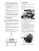
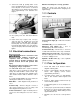
11. Tension the v-belt by pushing down on the motor and tightening the lock handle on the motor tilt plate. Correct tension is achieved when finger pressure between the two pulleys causes approximately a 1/2” deflection. See Figure 4. Machine must always be correctly grounded. NOTE: The power cord end will have to be changed to one rated 230V when changing to the higher voltage. 10.0 Controls Refer to Figure 5. Figure 4 12. Close pulley cover door and fasten with lock knob. Figure 5 13.
8. 9. when finger pressure on the belt between the two pulleys causes approximately a 1/2" deflection. Check to see that coolant level is adequate and turn on coolant pump if material to be cut requires it. Machine should be filled with four gallons of the proper coolant mixture. Follow the directions on the product maker’s label and fill the coolant tank through the chip tray area. Do not start cut on a sharp edge. 12.1 Adjusting vise square to blade 2.
5. Loosen lock knob and slide left blade guide arm (B) to the right as far as possible. 6. Remove old blade from both wheels and out of each blade guide. Even dull blades are sharp to the skin. Use extra caution handling band saw blades. 7. Install new blade making sure teeth are pointed downward in the proper cutting direction. If necessary, turn blade inside out. 8. Position blade on band wheels and tighten just enough to hold blade on wheels.
2. Turn on hydraulic valve (F, Figure 5). 3. Turn cutting pressure control valve (E, Figure 5) counterclockwise until it stops. 4. Place one end of a fish-type scale under the blade tension handle and lift the saw with the other end. The scale should indicate approximately 18-20 lbs. for the HBS-916W. For the HBS-1018W, it should indicate 22-24 lbs. 5. Adjust tension to approximately 18-20 lbs. (or 22-24 lbs.
4. Remove filler cap (A, Figure 12) and fill gear box with Mobil DTE® Oil Heavy Medium until level reaches dot in middle of sight glass. 13.1 Lubrication 5. Replace filler cap. All ball bearings are permanently lubricated and sealed. They require no further attention. 6. Connect machine to the power source. If the power cord is worn, cut, or damaged in any way, have it replaced immediately. Use a light machine oil to lubricate all other moving parts as needed.
14.1.
.1.
14.1.
14.1.4 Parts List for HBS-916W, HBS-1018W Index No. Part No. Description Size Qty 1 ................ HBS916W-01 ............ Base (S/N 8081108 and lower)................................ ...................................... 1 .................. HBS916W-01AG ....... Base (S/N 8081109 and higher) .............................. ...................................... 1 .................. HBS1018W-01 .......... Base (S/N 808718 and lower).................................. ...................................
Index No. Part No. Description Size Qty 39-2 ........... TS-1550061 .............. Washer .................................................................... 8mm .............................. 1 40 .............. HBS916W-40 ............ Motor Tilt Plate......................................................... ...................................... 1 .................. HBS1018W-40 .......... Motor Tilt Plate......................................................... ......................................
Index No. Part No. Description Size Qty 72 .............. HBS916W-72B .......... Magnetic Switch....................................................... ...................................... 1 .................. HBS1018W-72 .......... Magnetic Switch....................................................... ...................................... 1 .................. HBS916W-72-1 ......... Contactor (main motor) ............................................ ...................................... 1 ..........
Index No. Part No. Description Size Qty 103 ............ TS-1492021 .............. Hex Cap Bolt............................................................ M12x30 ......................... 2 103-1 ......... HBS916W-103-1 ....... Hex Cap Bolt............................................................ M12x20 ......................... 2 104 ............ HBS916W-104 .......... Motor Mount Bracket ............................................... ...................................... 1 105 ............
Index No. Part No. Description Size Qty 133 ............ TS-1551081 .............. Lock Washer (HBS-916W) ...................................... M8 ................................. 2 .................. TS-1551081 .............. Lock Washer (HBS-1018W) .................................... M8 ................................. 4 133-1 ......... TS-1550081 .............. Washer (HBS-916W) ............................................... M8 ................................. 2 .................. TS-1550081 ..
Index No. Part No. Description Size Qty 163 ............ HBS916W-163 .......... Stop Switch .............................................................. ...................................... 1 164 ............ HBS916W-164 .......... Pump Switch ............................................................ ...................................... 1 165N.......... HBS916W-165S ........ Feed Control - Hydraulic On/Off Valve .................... ......................................
Index No. Part No. Description Size Qty 201 ............ HBS916W-201 .......... Strain Relief Fitting .................................................. ...................................... 1 202 ............ HBS916W-202 .......... Power Cord.............................................................. ...................................... 1 203 ............ HBS916W-203 .......... Screw....................................................................... ......................................
14.2.
14.2.2 HBS-916W & 1018W – Gear Speed Reducing Box – Parts List Index No. Part No. Description Size Qty 1 ................ HBS916W-94-01 ....... Oil Seal .................................................................... 35x55x8 mm ................. 1 2 ................ HBS916W-94-02 ....... Bearing .................................................................... 30207 ............................ 1 3 ................ HBS916W-94-03 ....... Bearing ...................................................
15.0 Electrical Connections 15.
15.
This page intentionally left blank.
427 New Sanford Road LaVergne, Tennessee 37086 Phone: 800-274-6848 www.jettools.