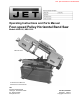
This .pdf document is bookmarked Operating Instructions and Parts Manual Four-speed Pulley Horizontal Band Saw Models HBS-916, HBS-1018 HBS-916 shown For HBS-916 and HBS-1018 manufactured 01-2020 and later JET 427 New Sanford Road LaVergne, Tennessee 37086 Ph.: 800-274-6848 www.jettools.com Part No.
Eyewear shall be impact resistant, protective safety glasses with side shields complying with ANSI Z87.1 specifications. Use of eye wear which does not comply with ANSI Z87.1 specifications could result in severe injury from breakage of eye protection. 1.0 IMPORTANT SAFETY INSTRUCTIONS 15. Wear proper apparel. No loose clothing or jewelry which can get caught in moving parts. Confine long hair. WARNING – To reduce risk of injury: 1. 2. 16.
41. Avoid dangerous working environments. Do not use stationary machine tools in wet or damp locations. Keep work areas clean and well lit. 27. Check damaged parts. Before further use of the machine, a guard or other part that is damaged should be carefully checked to determine that it will operate properly and perform its intended function. Check for alignment of moving parts, binding of moving parts, breakage of parts, mounting and any other conditions that may affect its operation.
2.0 Table of contents Section Page 1.0 IMPORTANT SAFETY INSTRUCTIONS ....................................................................................................... 2 2.0 Table of contents ............................................................................................................................................ 4 3.0 About this manual .......................................................................................................................................... 5 4.
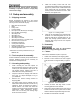
3.0 About this manual This manual is provided by JET, covering the safe operation and maintenance procedures for a JET Model HBS916 and HBS-1018 Horizontal Band Saw. This manual contains instructions on installation, safety precautions, general operating procedures, maintenance instructions and parts breakdown. Your machine has been designed and constructed to provide consistent, long-term operation if used in accordance with the instructions set forth in this document.
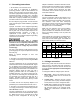
4.0 Specifications Table 1 Stock number Model number Motor and Electricals Main motor type Horsepower Phase Voltage Cycle Listed FLA (full load amps) Starting amps/inrush current Running amps, no load Motor speed On/off switch Power transfer Gearbox ratio Power cable and plug Recommended circuit size 1 Sound emission 2 Coolant pump Capacities 90 deg. Round 45 deg. 90 deg. Square (WxH) 45 deg. 90 deg. Rectangle (WxH) 45 deg.
1 Subject to local/national electrical codes. Circuit must be protected by appropriately rated fuses or breaker. 2 The specified values are emission levels and are not necessarily to be seen as safe operating levels. As workplace conditions vary, this information is intended to allow the user to make a better estimation of the hazards and risks involved only.
5. Read and understand the entire contents of this manual before attempting assembly or operation. Failure to comply may cause serious injury. 5.0 Setup and assembly Install four leveling screws with hex nuts (provided) into threaded holes on base flanges (Figure 5-1). Place a level on table surface and check side-to-side and front-to-back. Adjust leveling screws until machine is level in both directions, then tighten nuts. 5.
6. Attach motor tilt plate (B, Figure 5-3) to motor bracket using the provided locking handle (C, Figure 5-3) with lock washer and flat washer. using the saw, by checking the sight glass. (See Figure 11-2 for location.) Cutting fluid/coolant must be supplied by the operator. See sect. 11.0. 6.0 Electrical connections Electrical connections must be made by a qualified electrician in compliance with all relevant codes.
6.2 Grounding instructions adapter is available or should be used with this tool. If the tool must be reconnected for use on a different type of electric circuit, the reconnection should be made by qualified service personnel; and after reconnection, the tool should comply with all local codes and ordinances. 1. All Grounded, Cord-connected Tools: In the event of a malfunction or breakdown, grounding provides a path of least resistance for electric current to reduce the risk of electric shock.
7.2 Blade tension 7.0 Adjustments Blade tension has been preset by the manufacturer; if further adjustment is required, or after installing a new blade, turn handwheel (C, Figure 7-1) clockwise to approximately 25,000 pounds, as indicated on adjacent tension scale. 7.1 Removing and installing blades A general purpose blade has been installed, tensioned, and tracked on the band saw and should not require immediate attention. For future blade replacement, proceed as follows: 1.
7. 7.5.1 Rear support bearing Start saw blade, and slowly turn left hex adjustment screw (D3, Figure 7-2) to tilt idler wheel. Do not turn either of the other two adustment screws (D2). The rear support bearing (F, Figure 7-3) prevents deflection of blade under pressure from the workpiece. Set support bearing so that it nearly contacts back edge of blade but can still be turned by hand when blade is not running. NOTE: Turning screw inward causes blade to move toward wheel shoulder.
1. With bar stock securely clamped in the vise, make a cut through the bar stock (see Figure 74). 2. Mark the top of the bar stock. 3. Move the bar stock about 1/4-inch past the blade to prepare for a second cut. 7.7 Changing blade speeds Disconnect machine from power source before changing belt position. Failure to comply may cause serious injury. 1. Disconnect machine from power source. 2. Open pulley cover. 3. Support motor with one hand while loosening lock handle (C, Figure 5-3).
3. Make sure bolts on left/floating vise (M2) are loosened. Use handwheel to push vise against workpiece until it conforms to workpiece angle. Tighten bolts. 4. To expand clamping capacity, remove fixed jaw from inner holes and install it in outer holes. 7.10 Work stop adjustment The work stop assembly (Figure 7-7) allows multiple pieces to be cut to identical length. Screw rod (R) into hole in base, move bracket (S), and stop (T) to desired positions, and tighten all handles/levers.
Feed on/off selector (F) – Turn knob to “I” to open hydraulic cylinder and allow bow descent; turn to “O” to hold bow in raised position. 6. Blade will shut off at end of cut. (If blade does not shut off, limit switch stop bolt needs adjustment.) 10.1 Blade selection The HBS-916 and HBS-1018 are provided with a hook-type variable-tooth blade adequate for a wide range of jobs on a variety of common materials. Sect. 12.0 shows recommended speeds for various materials.
5. 6. Periodically apply light coat of machine oil to exposed metal surfaces, such as vise bed, to prohibit rust. When the blade has completed about 1/3 of the cut, increase the feed rate. Observe chip formation until cutting is at its most efficient rate (see sect. 10.3) and allow the saw to complete the cut. 11.1.1 Gear box oil change The blade is now considered ready for regular service. Drain and refill gear box according to Table 3 recommendations.
11.1.2 Servicing cutting fluid 11.2 Pulley alignment Pour cutting fluid or coolant mixture into chip tray so that it drains through strainer into basin. The sight glass is located on front of base, at lower left. Periodically check alignment of belt pulleys. Misalignment can cause rubbing and premature wear of the belt. To adjust, loosen set screw in motor sheave and slide sheave into alignment. Retighten set screw. Many cutting fluids on the market are formulated for special applications.
11.4 Lubrication schedule Item or location Recommended lubricant Frequency Vise lead screw Hydraulic cylinder pivot areas Blade tension shaft Light machine oil Monthly Light machine oil Every 6 months General purpose grease Every 6 months Blade brush shaft Light machine oil As needed Front slide General purpose grease Mobil® SHC Gear Oil 460, or equivalent. Fill qty.= 850mL (1/4 gal.) As needed Check periodically; top off as needed.
13.0 Troubleshooting HBS-916, HBS-1018 Table 4 * WARNING: Some corrections may require a qualified electrician. Symptom Possible Cause Correction* Motor will not start. No incoming power. Check plug connection. Blown electrical panel fuses or tripped circuit breaker. Replace fuses, or reset breaker. Defective motor, switch, power cable, or plug. Qualified electrician/service personnel should inspect these items. Excessive blade tension. Reduce tension. Drive belt tension too high.
Symptom Possible Cause Correction* Frequent blade breakage. Incorrect blade tension. Adjust blade tension. Incorrect blade speed or feed rate. Adjust accordingly. Workpiece loose in vise. Clamp workpiece securely. Blade rubs heavily on wheel shoulder. Adjust blade tracking. Tooth pitch too coarse for material. Use appropriate blade for material. Teeth in contact with workpiece before saw is started. Start motor before blade contacts workpiece. Blade guides are misaligned.
14.1.
14.1.
14.1.
14.1.4 HBS-916, HBS-1018 – Parts List Index No Part No Description Size Qty 1 ................ HBS916-01................ Base ........................................................................ ...................................... 1 .................. HBS1018-01.............. Base ........................................................................ ...................................... 1 2 ................ TS-1492071 .............. Hex Cap Screw ..............................................
Index No. Part No. Description Size Qty 43-1 ........... TS-1551061 .............. Lock Washer ............................................................ 8mm .............................. 2 44 .............. TS-1482021 .............. Hex Cap Screw ........................................................ M6x12 ........................... 4 45 .............. HBS916W-45 ............ Limit Switch ............................................................. ...................................... 1 47 ...
Index No. Part No. Description Size Qty 79-1 ........... TS-1550041 .............. Flat Washer (HBS-1018 only) .................................. M6 ............................... 12 80 .............. HBS916W-80G ......... Blade Wheel Cover - right ....................................... ...................................... 1 .................. HBS1018W-80AG ..... Blade Wheel Cover - right ....................................... ...................................... 1 81 .............. TS-1550041 ..
Index No. Part No. Description Size Qty .................. HBS1018W-111-2 ..... Capacitor Cover (not shown) ................................... ...................................... 1 112 ............ TS-1550061 .............. Flat Washer ............................................................. M8 ................................. 4 112-1 ......... TS-1551061 .............. Lock Washer ............................................................ M8 ................................. 4 113 .........
Index No. Part No. Description Size Qty 142 ............ HBS916W-142 .......... Plate ........................................................................ ...................................... 1 143 ............ TS-1524021 .............. Set Screw ................................................................ M8x10 ........................... 4 144 ............ HBS916W-144G ....... Blade Bracket - right ................................................ ...................................... 1 ....
Index No. Part No. Description Size Qty 171-3 ......... TS-1482031 .............. Hex Cap Screw (HBS-916W) .................................. M6x16 ........................... 2 172 ............ HBS916W-172 .......... Handle ..................................................................... ...................................... 1 173 ............ TS-1540081 .............. Hex Nut .................................................................... M12 ............................... 2 175 ..........
14.2.
14.2.2 HBS-916, HBS-1018 – Gear Speed Reducing Box – Parts List Index No. Part No. Description Size Qty .................. HBS916W-94G ......... Gear Box Assembly (includes #1 thru 23) ............... ...................................... 1 1 ................ HBS916W-94-01 ....... Oil Seal .................................................................... 35x55x8 mm ................. 1 2 ................ BB-30207 .................. Bearing .............................................................
5.0 Electrical Connections 15.
15.
16.0 Warranty and service JET warrants every product it sells against manufacturers’ defects. If one of our tools needs service or repair, please contact Technical Service by calling 1-800-274-6846, 8AM to 5PM CST, Monday through Friday. Warranty Period The general warranty lasts for the time period specified in the literature included with your product or on the official JET branded website. JET products carry a limited warranty which varies in duration based upon the product.
427 New Sanford Road LaVergne, Tennessee 37086 Phone: 800-274-6848 www.jettools.