
Product Manual


10
6.2 Grounding instructions
1. All Grounded, Cord-connected Tools:
In the event of a malfunction or breakdown,
grounding provides a path of least resistance for
electric current to reduce the risk of electric shock.
This tool is equipped with an electric cord having an
equipment-grounding conductor and a grounding
plug. The plug must be plugged into a matching
outlet that is properly installed and grounded in
accordance with all local codes and ordinances.
Do not modify the plug provided - if it will not fit the
outlet, have the proper outlet installed by a qualified
electrician.
Improper connection of the equipment-grounding
conductor can result in a risk of electric shock. The
conductor with insulation having an outer surface
that is green with or without yellow stripes is the
equipment-grounding conductor. If repair or
replacement of the electric cord or plug is
necessary, do not connect the equipment-grounding
conductor to a live terminal.
Check with a qualified
electrician or service personnel if the grounding
instructions are not completely understood, or if
in doubt as to whether the tool is properly
grounded. Failure to comply may cause serious
or fatal injury.
Use only 3-wire extension cords that have 3-prong
grounding plugs and 3-pole receptacles that accept
the tool's plug.
Repair or replace damaged or worn cord
immediately.
2. Grounded, cord-connected tools intended for use
on a supply circuit having a nominal rating less than
150 volts:
This tool is intended for use on a circuit that has an
outlet that looks like the one illustrated in A, Figure
6-1. An adapter, shown in B and C, may be used to
connect this plug to a 2-pole receptacle as shown in
B if a properly grounded outlet is not available. The
temporary adapter should be used only until a
properly grounded outlet can be installed by a
qualified electrician. The green-colored rigid ear,
lug, and the like, extending from the adapter must
be connected to a permanent ground such as a
properly grounded outlet box. Whenever the
adaptor is used, it must be held in place by a metal
screw.
In Canada, the use of a temporary adaptor is not
permitted by the Canadian Electrical Code, C22.1.
3. Grounded, cord-connected tools intended for use
on a supply circuit having a nominal rating between
150 - 250 volts, inclusive:
This tool is intended for use on a circuit that has an
outlet that looks like the one illustrated in D, Figure
6-1. Make sure the tool is connected to an outlet
having the same configuration as the plug. No
adapter is available or should be used with this tool.
If the tool must be reconnected for use on a different
type of electric circuit, the reconnection should be
made by qualified service personnel; and after
reconnection, the tool should comply with all local
codes and ordinances.
6.3 Extension cords
The use of extension cords is discouraged. Try to
position equipment near the power source. If an
extension cord becomes necessary, use only three-
wire extension cords that have three-prong
grounding type plugs and three-prong receptacles
that accept the tool's plug. Replace or repair
damaged or worn cord immediately.
Make sure your extension cord is good condition,
and is heavy enough to carry the current your
product will draw. An undersized cord will cause a
drop in line voltage resulting in loss of power and
overheating.
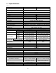
Table 2 shows the correct size to use depending on
cord length and nameplate ampere rating. If in
doubt, use the next heavier gage. The smaller the
gage number (AWG), the heavier the cord.
Amp rating Volts Total length of cord in feet
More
Than
Not
More
Than
120
240
25
50
50
100
100
200
150
300
AWG
0 6 18 16 16 14
6 10 18 16 14 12
10 12 16 16 14 12
12 16 14 12
Not
Recommended
Extension Cord Recommendations
Table 2
6.4 Voltage conversion
Before wiring, make sure saw is disconnected from
power source or the fuses have been removed or
breakers tripped in the circuit to which the saw will
be connected. Use appropriate Lock-Out/Tag-Out
procedures.
To change the HBS-916 voltage input to 230 volt:
1. Main motor – Open motor junction box cover.
Follow diagram inside cover to reconnect the
incoming leads.
2. Coolant pump – Remove chip pan, remove
junction box cover on pump, and follow diagram
inside junction box cover to change the leads.
3. Power cord – Replace the provided 115V plug
with a UL/CSA listed 230V plug. Or “hardwire”
the machine directly to an electrical panel.
(Make sure a disconnect is available for the
operator.)