
Product Manual


9
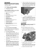
6. Attach motor tilt plate (B, Figure 5-3) to motor
bracket using the provided locking handle (C,
Figure 5-3) with lock washer and flat washer.
Figure 5-3: motor locking handle
Note: Locking handle (C) is adjustable. Pull out on
handle and rotate it on the pin to a more convenient
position, then release it. Make sure it reseats on the
pin.
5.4.2 V-belt and pulley cover
1. Loosen tilt locking handle (C, Figure 5-3), and
allow motor to lower. Place v-belt around both
pulleys.
2. Push up motor and tighten tilt locking handle (C)
to tension v-belt. Correct tension is achieved
when finger pressure midway between the two
pulleys causes approximately 1/2” deflection.
See Figure 5-4.
3. Remove two hex cap bolts and washers (D,
Figure 5-4).
4. Position belt cover (E, Figure 5-4) around pulley
shafts and attach to saw with the two bolts and
washers.
5. Close pulley cover and fasten with knob.
Figure 5-4: installing belt and pulley cover
5.5 Control box
Mount the control box atop the bow using the screws
that are preinstalled in the two holes.
5.6 Lubrication
The band saw is shipped with the appropriate level
of gear oil. The operator should verify this before
using the saw, by checking the sight glass. (See
Figure 11-2 for location.)
Cutting fluid/coolant must be supplied by the
operator. See sect. 11.0.
6.0 Electrical connections
Electrical connections must be
made by a qualified electrician in compliance
with all relevant codes. This machine must be
properly grounded while in use to protect the
operator from electrical shock and possible fatal
injury.
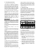
The HBS-916 (#414468) is rated for 115/230V
single phase power, and is pre-wired 115 volt. It is
supplied with a cord and plug designed for use on a
circuit with a grounded outlet that looks like the one
pictured in A, Figure 6-1. It may be converted to
230V power, see sect. 6.3.
The HBS-1018 (#414473) is rated at 230V only,
single phase, and is supplied with a cord and plug
designed for use on a circuit with a grounded outlet
that looks like the one pictured in D, Figure 6-1.
Confirm that power available at the saw’s location
matches that for which the saw is wired.
Before wiring, make sure saw is disconnected from
power source or the fuses have been removed or
breakers tripped in the circuit to which the saw will
be connected. Use appropriate Lock-Out/Tag-Out
procedures.
6.1 Connecting motor cable
1. Loosen strain relief nut on motor junction box.
Remove junction box cover.
2. Insert motor cable (see F, Figure 5-2) through
strain relief and connect the leads inside the
box. Make sure the grounding wire is properly
connected.
3. Tighten strain relief nut and replace junction box
cover.
See sect. 4.0 for recommended circuit sizes. Local
codes take precedence over recommendations.
Figure 6-1: plug configurations