Operating Instructions and Parts Manual Lever Operated Chain Hoist JLH Mini Series 0.25T and 0.5T 1/4 Ton model shown WALTER MEIER (Manufacturing) Inc. 427 New Sanford Road LaVergne, Tennessee 37086 Ph.: 800-274-6848 www.waltermeier.com Part No. M-181205 Revision A 06/2011 Copyright © 2011 Walter Meier (Manufacturing) Inc.
Warranty and Service Walter Meier (Manufacturing) Inc., warrants every product it sells. If one of our tools needs service or repair, one of our Authorized Service Centers located throughout the United States can give you quick service. In most cases, any of these Walter Meier Authorized Service Centers can authorize warranty repair, assist you in obtaining parts, or perform routine maintenance and major repair on your JET ® tools.
Table of Contents Warranty and Service..........................................................................................................................2 Table of Contents ...............................................................................................................................3 Warning .............................................................................................................................................4 Introduction .......................................
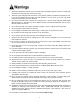
Warning 1. Read and understand the entire owner’s manual before attempting operation. Failure to comply with instructions and warnings may cause serious injury. 2. This lever hoist is designed and intended for use by properly trained and experienced personnel only. If you are not familiar with the proper and safe operation of a lever hoist, do not use until proper training and knowledge have been obtained. 3. Do not use this lever hoist for other than its intended use.
Introduction This manual is provided by Walter Meier (Manufacturing) Inc., covering the safe operation and maintenance procedures for the JET JLH Mini Series Lever Hoists. This manual contains instructions on installation, safety precautions, general operating procedures, maintenance instructions and parts breakdown. This tool has been designed and constructed to provide years of trouble free operation if used in accordance with instructions set forth in this manual.
Specifications (JLH-25/50) Stock Number Description 181205 181210 181215 181505 181510 181515 JLH-25-5 JLH-25-10 JLH-25-15 JLH-50-5 JLH-50-10 JLH-50-15 Min. Distance Rated Standard between Capcty. Lift hooks (in.) “A” (ton) (ft.) 0.25 0.25 0.25 0.5 0.5 0.5 5 10 15 5 10 15 1.40 1.40 1.40 1.65 1.65 1.65 Lbs. No. Load Pull Lever of Chain Lift per to Lift Length falls Diameter full turn capacity (in.) “B” (mm) (in.) 1 1 1 1 1 1 3.2 3.2 3.2 4.3 4.3 4.3 0.42 0.42 0.42 0.33 0.33 0.33 44.97 44.97 44.
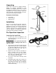
Unpacking Open carton and check for shipping damage. Report any damage immediately to your distributor and shipping agent. Do not discard any shipping material until the Lever Hoist is assembled and running properly. Read this entire instruction manual thoroughly for set-up, maintenance and safety instructions. Contents of the Carton 1 1 1 Lever Hoist Owner's Manual Warranty Card Installation Support for the hoist may be hook, clevis pin, trolley, or beam clamp.
The load chain supplied with your JET lever hoist is designed, manufactured, and tested for proper fit and durability. If chain should ever need replacing, for your own safety use factory replacement chain only. Use of other than factory replacement chain may cause serious injury and/or damage to the lever hoist. Never extend load chain by welding a second piece to the original. Inspecting Hooks It is important to check top and bottom hooks for proper opening and other signs of deformation or damage.
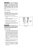
Operation The JLH Mini Lever Hoist may be used either in vertical position as a hoist; or in angled or horizontal position as a puller. Below is the general procedure for operating the hoist: 1. Set the top hook securely. 2. Correctly center the load on the bottom hook (Figure 4). Incorrect loading is dangerous to the operator, the lever hoist, and the load. Figure 4 • Never load the hook in front of the safety latch (A, Figure 5). • Never load the hook tip (B, Figure 5).
Precautions • During lifting operations, do not stand under the load. • Do not use any extension on the lever handle. Do not use your foot to apply pressure to the lever handle. • Prevent the chain from dragging over sharp edges or corners. This will cause links to weaken, bend, or break. • When connecting to a wire rope sling, the lever hoist must be applied along a straight line parallel to the surface on which it is resting. See Figure 6. • When lifting loads, hook the load with slings.
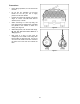
Maintenance The lever hoist should be stored in a clean, dry environment. Clean and oil the hoist before storage. Hoists that are installed out-of-doors should be covered or brought inside when not in use. Periodically apply a light coat of 30W oil to the load chain. Also lubricate the safety latches and the bearings in the hooks. Allowable Limits for Load Chain and Hooks Hoist Capacity 5 Links Normal (mm) 5 Links Limit 0.25 ton 0.5 ton 45 60 46.3 61.
Troubleshooting The numbers in parentheses refer to the parts breakdown on the following page. Trouble Probable Cause Remedy* Hoist will not lift (no clicking sound). Pawl (#21) not engaging ratchet disc (#24); possible dirt or foreign material. Clean and lubricate pawl/ratchet disc assemblies. Pawl spring (#20) is damaged. Replace pawl spring. Selector switch spring is loose or damaged. Tighten or replace selector switch spring. Dirt/corrosion/foreign material in hoist components.
JLH Series Lever Hoists (JLH-25/50) 13
Parts List: JLH-25 (0.25 Ton) Parts listed under each assembly are parts that make up that assembly. Index No. Part No. Description Size Qty 1 .............. JLH25-1 ..................Top Hook Assembly ............................................................................ 1 ........ ...............................Top Hook ........................................................................................... 1 ........ ...............................Safety Latch Kit ...........................
Index No. Part No. Description Size Qty 36 ............ JLH25-36 ................Snap Ring ........................................................22mm ........................ 1 37 ............ JLH25-37 ................Handwheel ......................................................................................... 1 38 ............ JLH25-38 ................Snap Ring ........................................................7mm .......................... 1 40 ............ JLH25-40 ................
Index No. Part No. Description Size Qty 22 ............ JLH25-22 ................Snap Ring (0.25,0.5 ton) ...................................6mm .......................... 2 23 ............ JLH50-23 ................Brake Seat ......................................................................................... 1 24 ............ JLH50-24 ................Ratchet Disc ....................................................................................... 1 25 ............ JLH50-25 ................