This .pdf document is bookmarked Operating Instructions and Parts Manual 10 x 14 Horizontal Mitering Band Saw Model MBS-1014W JET 427 New Sanford Road LaVergne, Tennessee 37086 Ph.: 800-274-6848 www.jettools.com Part No.
1.0 Warranty and Service JET warrants every product it sells against manufacturers’ defects. If one of our tools needs service or repair, please contact Technical Service by calling 1-800-274-6846, 8AM to 5PM CST, Monday through Friday. Warranty Period The general warranty lasts for the time period specified in the literature included with your product or on the official JET branded website. • JET products carry a limited warranty which varies in duration based upon the product.
2.0 Table of contents Section Page 1.0 Warranty and Service ..................................................................................................................................... 2 2.0 Table of contents ............................................................................................................................................ 3 3.0 Warnings ........................................................................................................................................
11. Replace warning labels obscured or removed. 1. Read and understand the entire instruction manual before attempting assembly or operation. 2. All JET bandsaws are designed and intended for use by properly trained and experienced personnel only. If you are not familiar with the proper and safe operation of a bandsaw, do not use until proper training and knowledge have been obtained become 13. Give your work undivided attention.
4.0 About this manual This manual is provided by JET covering the safe operation and maintenance procedures for a JET Model MBS-1014W Horizontal Saw. This manual contains instructions on installation, safety precautions, general operating procedures, maintenance instructions and parts breakdown. Your machine has been designed and constructed to provide consistent, long-term operation if used in accordance with the instructions as set forth in this document.
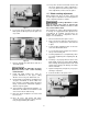
8.0 Assembly 6.0 Uncrating and Cleanup NOTE: Read and understand the entire manual before attempting setup or operation. 1. Finish uncrating the saw and inspect for damage. Should any have occurred, contact your local distributor. 2. Remove all bolts shipping base. 3. Leave packing material between vice clamps and saw head intact until bandsaw has been lifted to its final position. 4. Clean all rust protected surfaces with kerosene or diesel oil to remove protective coating.
• 11. Tension the v-belt by pushing down on the motor and tightening the lock handle on the motor tilt plate. Correct tension is achieved when finger pressure between the two pulleys causes approximately a 1/2” deflection. Machine must always be correctly grounded. 12. Close pulley cover door and fasten with lock knob. Note: the power cord end will have to be changed to one that is rated 460V when changing voltage. 13. Fasten work stop rod (#241, sect. 14.1.
6. 7. Material to be cut must be securely held in vise. 8. Check to see that coolant level is adequate and turn on coolant pump if material to be cut requires it. Machine should be filled with four gallons of the proper coolant mixture. Follow the directions on the product maker’s label and fill the coolant tank through the chip tray area. 9. 12.3 Adjusting feed rate Select proper speed and feed rate for material being cut. Consult Machinery’s Handbook or similar source for speed and feed charts.
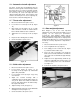
13. Turn power off and recheck blade tension and wire brush adjustment. If further adjustment is necessary, disconnect saw from power source, make adjustments, and reconnect to power. 12.5 Blade tracking adjustment Blade tracking has been set at the factory and should require no adjustment. If a tracking problem occurs, adjust the machine as follows: Tracking adjustment is done with the wheel covers open to observe the blade. Use extreme caution so as not to come into contact with the blade. Figure 7 6.
12.6 Automatic shut-off adjustment The motor should shut off immediately after the blade has cut through the material and just before the head comes to rest on the horizontal stop bolt. If the machine continues to run after the work piece has been fully cut, locate and adjust the micro switch mounting plate down. If the machine shuts off before the work piece has been completely cut, move the micro switch mounting plate up. 12.7 Thrust roller adjustment 1. Disconnect machine from power source. 2.
To adjust the 45° stop: 12.10 Angle adjustment To swivel the saw arm up to a 45° angle: 1. Disconnect machine from power source. 2. Lower saw arm completely. 3. Pull the lock lever toward the front of the saw and push the saw arm assembly against the 45° stop. 1. Disconnect machine from power source. 2. Pull the handle (A, Figure 13) toward the front of the saw. 3. Rotate the upper assembly to the desired angle. 4. Place a 45° angle square on the blade and the fixed vise jaw. 4.
1. Loosen adjustable handle (index #219,221) to desired location. 2. Set the vise to desired angle, reinstall nuts and tighten the nut and bolt assemblies. 3. Adjust the movable vise parallel to the fixed vise by loosening bolt (A, Figure 17), adjusting to parallel, and tightening bolt. To change gear box lubricant: 1. Disconnect machine from power source. 2. Open drain plug and allow lubricant to drain completely. Drain plug may be found on lower rear of gear case.
14.1.
.1.
14.1.3 Parts List for MBS-1014W Band Saw Index No Part No Description Size Qty 1A .............. MBS1014W-1AG....... Base......................................................................... ...................................... 1 2 ................ Ts-1492071 ............... Hex Cap Bolt............................................................ M12x70 ......................... 4 3 ................ TS-1540081 .............. Hex Nut .................................................................
Index No Part No Description Size Qty 57 .............. TS-0561051 .............. Hex Nut .................................................................... 1/2"................................ 2 58 .............. HBS916W-58 ............ Spring Bracket ......................................................... ...................................... 1 59 .............. HBS916W-59 ............ Adjustable C-Bolt ..................................................... ......................................
Index No Part No Description Size Qty 106 ............ TS-1506011 .............. Hex Socket Cap Screw ............................................ M12x20 ......................... 6 107 ............ HBS916W-107 .......... Locking Handle ........................................................ ...................................... 1 108 ............ TS-1550061 .............. Washer .................................................................... 8mm .............................. 1 109 ............
Index No Part No Description Size Qty 156 ............ MBS1014W-156 ........ Hex Cap Bolt with Rubber Stopper .......................... M12x60 ......................... 1 157 ............ HBS1018W-157AG ... Blade Guard ............................................................ ...................................... 1 157-1 ......... HBS1018W-157-1G .. Blade Guard - down ................................................. ...................................... 1 158 ............ HBS916W-158 ..........
Index No Part No Description Size Qty 217 ............ MBS1014W-217 ........ Cotter Pin ................................................................. ...................................... 1 218 ............ MBS1014W-218 ........ Spring Cover ............................................................ ...................................... 1 219 ............ MBS1014W-219 ........ Adjustable Handle ................................................... ...................................... 1 220 .....
14.2.
14.2.2 MBS-1014W – Gear Speed Reducer Assembly – Parts List Index No Part No Description Size Qty 1 ................ HBS916W-94-01 ....... Oil Seal .................................................................... 35x55x8 mm ................. 1 2 ................ BB-30207 .................. Bearing .................................................................... 30207 ............................ 1 3 ................ BB-6207 .................... Bearing ...........................................
15.0 Electrical Connections 15.1.1 Electrical Connections – 1 Phase 15.1.
15.2.1 Electrical Connections – 3 Phase 15.2.
427 New Sanford Road LaVergne, Tennessee 37086 Phone: 800-274-6848 www.jettools.