This .pdf document is bookmarked Operating Instructions and Parts Manual VOLTTM Series Electric Chain Hoists 1/4 ton model shown JET 427 New Sanford Road LaVergne, Tennessee 37086 Ph.: 800-274-6848 www.jettools.com Part No.
1.0 Warranty and Service JET warrants every product it sells against manufacturers’ defects. If one of our tools needs service or repair, please contact Technical Service by calling 1-800-274-6846, 8AM to 5PM CST, Monday through Friday. Warranty Period The general warranty lasts for the time period specified in the literature included with your product or on the official JET branded website. • JET products carry a limited warranty which varies in duration based upon the product.
2.0 Table of contents Section Page 1.0 Warranty and Service ..................................................................................................................................... 2 2.0 Table of contents ............................................................................................................................................ 3 3.0 Safety warnings ...................................................................................................................................
chain. If the chain hoist is damaged, do not use until it has been repaired or replaced. 14. Do not use more than one chain hoist to lift or move a load. If this is unavoidable, each chain hoist must have the same capacity as the load to be moved. 3.0 Safety warnings 1. 2. Read and understand the entire owner's manual before attempting assembly or operation. 15. Never allow the load chain to “set” over sharp edges. All lifts must be made with straight chain that is free of obstacles.
Familiarize yourself with the following safety notices used in this manual: This means that if precautions are not heeded, it may result in minor injury and/or possible machine damage. This means that if precautions are not heeded, it may result in serious injury or possibly even death. 3.1 Important notice It is the responsibility of the owner/user to install, inspect, operate and maintain this hoist in accordance with OSHA regulations and ANSI/ASME B30.
.0 Glossary Creep speed: Slow, constant, fixed rate of motion of a hoist. Magnetic disc brake: A stopping device controlled by the application of electrical current to the coil of an electromagnet, which draws away an armature allowing rotation of the shaft. When the magnet is de-energized, the armature moves back toward the brake face and squeezes together friction discs – the torque is applied to the hub and stops shaft rotation.
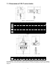
.0 Dimensions of VOLT series hoists Figure 1: 1/4 ton to 5 ton hoists 1/4 ton 1/2 ton 1 ton 2 ton 3 ton 5 ton mm in. mm in. mm in. mm in. mm in. mm in. C 505 19.88 505 19.88 550 21.7 605 23.8 605 23.8 665 26.2 D 610 24.02 610 24.02 630 24.80 780 30.71 780 30.71 870 34.25 a 626 24.6 626 24.6 666 26.2 694 27.32 694 27.32 694 27.32 b 286 11.3 286 11.3 286 11.3 430 16.93 430 16.93 430 16.93 d 317 12.48 317 12.48 317 12.48 336 13.23 336 13.23 336 13.23 e 309 12.2 309 12.2 349 13.7 358 14.09 358 14.
Table 3 Custom chain lengths may be available: contact your dealer or Walter Meier (Mfg.) Inc. 50% Duty Cycle = maximum on time: 30 min/hr.; maximum number of starts: 300/hr. 40% Duty Cycle = maximum on time: 24 min./hr.; maximum number of starts: 240/hr. 1 2 8.0 Specifications of VOLT Series hoists 3 Gross weight includes shipping/packaging materials.
screws. See Figure 4. On 3- to 10-ton models, secure the cable loop to the eyebolt on the side of the hoist. 9.0 Unpacking Open shipping container and check for shipping damage. Report any damage immediately to your distributor and shipping agent. Do not discard any shipping material until hoist is installed and running properly. 9.
The oil in the gearbox should be changed annually, or more frequently under severe service, as follows. Do not dump chain by hand into the chain container! By not following the above steps, the chain can become twisted or kinked and can damage the hoist. Use either of these recommended oil brands: Mobilgear XMP 100 Shell Omala S2 G 100 Capacities: 1/4T,1/2T,1T Hoists – 0.8 Liters (0.21 gal) 2T,3T,5T,10T Hoists – 1.5 Liters (0.4 gal) To drain and refill gearbox (refer to Figure 5): 1.
hoist must remain motionless when power is applied. Find and correct any problems before continuing. all local codes and ordinances. Do not modify the plug – if it will not fit the outlet, have the proper outlet installed by a qualified electrician. Improper connection of the equipment-grounding conductor can result in a risk of electric shock. The conductor with insulation having an outer surface that is green with or without yellow stripes is the equipment-grounding connector. 2.
13.0 Operation The load chain supplied with your JET chain hoist is designed, manufactured, and tested for proper fit and durability. Over a period of time, the chain may need to be replaced. For your own safety, use factory replacement chain only. Use of other than factory replacement chain may cause serious injury and/or damage to hoist. 13.1 Controls Refer to Figure 8. Allow hoist to come to a full stop before changing direction.
Figure 20 Figure 9 3. 4. Check again that load is properly slung, is directly under hoist, and will not suddenly swing or twist. 5. Raise load an inch or two above ground and stop. Observe load for a few moments, looking for signs that load or hoist system is unstable, or other indications of a problem. 6. The magnetic disc brake provides dependable and rapid stops, and produces less wear on parts than standard mechanical braking systems.
4. 14.0 Adjustments 14.1 Replacing load chain Using a C-link, connect the new chain to the old chain. Be sure vertical link welds face away from load sheave (see Figure 13 and its accompanying text). Over time, the load chain will wear or elongate. This can cause damage to hoist, breakage, or nonengagement of the load sheave. The following procedures describe replacing the load chain for single and multiple fall hoists. These procedures should be performed by qualified persons only.
14.6 Dual/multiple fall chain hoists 6. Support the load hook so that the load chain can pass through the chain sheaves smoothly. The link on the load side end must be a vertical link. If it is a horizontal link, the chain will have a twist in it. 7. Press the DOWN button to move the chain through the hoist. Keep tension on the chain as you pull it through to the load side, until the C-link(s) clears the hoist at the load side. Continue pressing DOWN until the new chain clears the load hook. 8.
15.0 Inspection and maintenance All repairs and adjustments are to be performed by qualified persons using procedures that are approved for the hoist system being serviced. All safety-related deficiencies discovered in the inspection are to be corrected before hoist is placed back into service. Check for internal damage whenever external damage has occurred. Read and follow all relevant ANSI Inspection and Maintenance standards, particularly ANSI/ASME B30.16 Overhead Hoists (Underhung).
16.0 Inspection schedules The VOLT series Hoist should be given an initial inspection upon installation and prior to use (see also PreOperation Inspection in this manual). Following that, it must be inspected by a designated person at the time interval noted below. Dated inspection and repair reports must be maintained. Copies of all reports must be available to service personnel.
17.0 Allowable limits 17.1 Hook wear limits (top and bottom) Replace the hook when the A, B, or C measurements, as shown in Figure 16, reach the limit shown in the tables below. Never heat-treat the hook or attach anything to the hook by welding. NOTE: Excessive hook throat opening or twist indicates abuse or overloading of the hoist. If such deformation is discovered, inspect the hoist, chain and all supporting members very carefully for additional indications of excessive hoist loading.
18.0 Brake adjustment and maintenance For normal brake operation, the following requirements must be met: 1. 2. 3. 4. Location altitude must not exceed 2,000 meters (6500 feet) and relative humidity must be under 85%. Brake is free of corrosion or dust. Insulation grade is B, protection grade IP23, and voltage fluctuation remains between +5% and -15%. Surrounding temperature must be between -5 to 40°C (23 to 104°F) and the fricative surface is free from oil. 5.
19.
20.0 Troubleshooting the VOLT series Hoist Table 7 Important: Any servicing performed on the brake, inverter, or other electrical components must be done by qualified persons only. Trouble Hoist will not respond to controls. Probable Cause Suggested Remedy Move hook in opposite direction. If limit Limit switch is tripped. switches need adjustment, have qualified person inspect them. Hoist overloaded. Reduce load to within rated capacity. Check hoist connections to power No incoming power, or low voltage.
Trouble Probable Cause Limit switch failure. Bad connection of limit switch leads. Abnormal sounds. Limit switch damaged. Brake out of adjustment. Suggested Remedy Inspect contacts of leads and limit switches. Replace. Inspect and adjust/repair as needed. 21.0 Replacement Parts Replacement parts are listed on the following pages. To order parts or reach our service department, call 1800-274-6848, Monday through Friday (see our website for business hours, www.jettools.com).
21.1.1 Exploded View for 0.
21.1.2 Parts List for 0.25T to 5T Hoists (VOLT series) Note: Items showing (5T) also pertain to the 10-ton model. Index No. Part No. Description Size Qty 1 ................ TS-1502091 .............. Socket Head Cap Screw (1/4T~5T)......................... M5x40 ........................... 4 2 ................ VOLT-100-03P-2 ....... Inverter Side Cover (1/4T,1/2T,1T) .......................... ...................................... 1 .................. VOLT-300-03P-2 .......
Index No. Part No. Description Size Qty 26 .............. VOLT-100-03P-26 ..... Friction Disc Assembly (1/4T,1/2T,1T) .................... ...................................... 2 .................. VOLT-300-03P-26 ..... Friction Disc Assembly (2T,3T,5T) .......................... ...................................... 2 27 .............. VOLT-025-03P-27 ..... Dish Spring (1/4T,1/2T) ........................................... ...................................... 2 .................. VOLT-100-03P-27 .
.................. VOLT-300-03P-461 ... Friction Disc (2T,3T,5T) ........................................... ...................................... 1 46-2 ........... VOLT-025-03P-462 ... Key (1/4T,1/2T,1T)................................................... ...................................... 1 .................. VOLT-300-03P-462 ... Key (2T,3T,5T)......................................................... ...................................... 1 46-3 ........... VOLT-025-03P-463 ...
69 .............. TS-1502041 .............. Socket Head Cap Screw (1/4T,1/2T,1T) ................. M5x16 ........................... 2 .................. TS-1503041 .............. Socket Head Cap Screw (2T,3T,5T)........................ M6x16 ........................... 2 70 .............. VOLT-025-03P-70 ..... Chain Stop (1/4T)(Set of 2 pcs) ............................... ...................................... 1 .................. VOLT-050-03P-70 ..... Chain Stop (1/2T)(Set of 2 pcs) .....................
104 ............ VOLT-050-03P-104 ... Ballast Weight (1/4T,1/2T) ....................................... ...................................... 1 .................. VOLT-100-03P-104 ... Ballast Weight (1T) .................................................. ...................................... 1 .................. VOLT-300-03P-104 ... Ballast Weight (2T,3T,5T) ........................................ ...................................... 1 105 ............ VOLT-025-03P-105 ... Name Plate (1/4T,1/2T,1T) ..
21.1.3 Parts List for Top & Bottom Hook Assemblies, 0.25T to 5T Hoists (VOLT) Index No. Part No. Description Size Qty 32-1 ........... VOLT-025-03P-32-1...... Top Hook (1/4T) ................................................... ...................................... 1 .................. VOLT-050-03P-32-1...... Top Hook (1/2T) ................................................... ...................................... 1 .................. VOLT-100-03P-32-1...... Top Hook (1T) ...............................
21.2.1 Exploded View for 10-Ton Hoist (VOLT series) Note: The 10-Ton hoist consists of two hoist bodies which are also used on the 3- and 5-Ton models; consult the parts list and breakdown for the 3-Ton model. Top and Bottom Hook Assemblies for the 10-Ton are listed on the following pages.
21.2.2 Parts List for Top and Bottom Hook Assemblies, 10-Ton Hoist (VOLT series) Index No. Part No. Description Size Qty 32-1 ........... VOLT-1000-03P-32-1......... Top Hook......................................................... ...................................... 1 32-2 ........... VOLT-1000-03P-32-2......... Safety Latch Assembly (includes #32-3,32-4,32-5) ............................... 1 32-3 ........... TS-1541041 ....................... Nylon Lock Hex Nut ....................................
Index No. Part No. Description Size Qty 67-19 ......... VOLT-1000-03P-6719 ........ Fixing Bolt ....................................................... .................................... 16 67-20 ......... VOLT-1000-03P-6720 ........ Hex Bolt........................................................... M16x160 ....................... 3 67-21 ......... VOLT-1000-03P-6721 ........ Position Plate 2 ............................................... ...................................... 2 67-22 .........
22.0 Electrical connections for VOLT series Hoist 22.
22.
22.
427 New Sanford Road LaVergne, Tennessee 37086 Phone: 800-274-6848 www.jettools.