
Installation Manual


CONFIDENTIAL
RF Module Installation Manual
JETCO Model JTR-01
February 27, 2019
JTR-01 RF Module - Installation Manual.docx 2019-02-27 Page
7
of 8
Serial RF Module Configuration
Base Station modules are configured at the factory and there are no user configurations
available.
RF Modules are configured at the factory to use two character or nine character addresses. If
nine character addressing is configured, there are no user configurations available.
If two character addressing is configured, the RF modules can have their addresses configured
by attaching them to a USB port with the following steps:
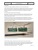
1. Attach an RF Module to a Windows 10 based computer. An adapter cable will be
needed to attach the standard computer USB A female port to the RF Module USB
micro B male port.
2. The Device Manager will show that a new Serial Port has been added. The port
number that is shown will be used to communicate with the RF module.
3. Bring up a terminal emulator program, such as Tera Term, or any program that can
send ASCII string through a serial port. Attach the emulator program to the serial port
shown by Device Manager for the RF module.
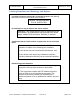
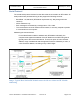
4. To see the present RF Module address: Send the character ‘^’ followed by a CR to
the RF Module. The response should look somewhat like:
“RFMv06:190225000, 915 MHz,Addr:0000000000 81 R 1 E0”
Where the characters ‘81’ is the two character address of the module.
5. To change the address, send a ‘%’ followed by a new two character address and a
carriage return. i.e. Send “%85” followed by a CR to set the new address to ‘85’.
The RF Module should return the ASCII string “OK”<CR>
6. If the address change was successful, sending the ‘^’ <CR> string again will return
the string:
“RFMv06:190225000, 915 MHz,Addr:0000000000 85 R 1 E0”
Contact JETCO for assistance with setting up and troubleshooting issues with the JTR-01 Base
Station and RF modules.