ENGLISH extended serie radio control system DUPLEX Tx transmitter modules (along with DUPLEX Rx receceivers) constitute the base of a complex system working in the 2.4GHz band, assigned to remote control of models. These modules may be installed into transmitters which in a convenient way transmit stick and control element positions. Recently most of available transmitters working with PPM mode are suitable for this purpose.
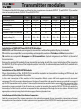
EN Duplex Transmitter modules Transmitter modules TX Modules of the DUPLEX system are offered as plug-in replacement modules DUPLEX TF and DUPLEX TG, as well as internal assembly modules DUPLEX TA and DUPLEX TU2.
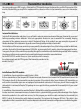
EN Transmitter modules the corresponding pins GND, supply +Ubat and the PPM signal between the transmitter and the IN connector of the module. Mechanically you may fix the module and the connector either to the transmitter case or the transmitter tray. Internal Installation: Switch off the transmitter and place it on a soft pad in order to prevent mechanical damage. Remove the cover and before proceeding remove batteries.
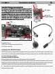
Transmitter modules EN SWTU2 Connection of the external buzzer and earphones: An earphone or an additional external buzzer may be connected to the module TU2. Connection to the module TU2 is carried out by means of the gold plated pins as shown in the picture (polarity is of no significance). The module TU2 is able to recognize the connection of earphones and automatically disables the buzzer for generation of telemetric alerts.
Transmitter modules 3. After removal of the case disconnect the antenna cable from the connector of the original module 4. Open up the hole for the originally used push button in the case to 6 mm dia. 5. Connect the antenna cable to the TA transmitter module connector and put everything back into the case. 6. Close the case again by means of the two screws, shift the antenna in place and plug-in the module back into the transmitter. 7.
Transmitter modules EN Plug-in the shorting plug into the connector "Ext." and switch on the receiver. Then switch on the transmitter. If pairing was successful the transmitter will confirm this by a short beep (by a lower and then a higher tone). If no confirmation of a successful pairing occurs, try to repeat the whole procedure or try to verify via the JETIBOX whether the receiver is in „Normal Mode“ (a receiver in „Clone Mode“ is not allowed to transmit and hence cannot confirm pairing).
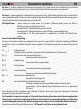
Transmitter modules EN Connection of the JETIBOX As already mentioned the JETIBOX terminal can be connected to DUPLEX Tx transmitters. With the help of this terminal transmitter data and parameters as well as currently connected equipment (receivers, telemetric senzors etc.) may be displayed and adjusted. DUPLEX transmitter modules are equipped with a three pin connector (see marking) intended for connection of the JETIBOX.
Transmitter modules EN P - after switching on the transmitter has not yet been paired (did for the moment not yet find a paired receiver) S - there are no receiver data available (bad signal) T - low voltage of the transmitter battery B - low voltage of the receiver battery I - there are no PPM pulses from the transmitter accessible (installation error, PCM mode etc.) Most of the conditions shown are accompanied by acoustic signals. By pushing button U (upward arrow) range test mode may be activated.
Transmitter modules EN Mx Tone 1 - enables adjustment of warning tone frequency (Hz), which reveals alert conditions of the connected equipment Mx (usually a telemetric senzor). A value of 0 indicates that the warning tone is switched off. Mx Tone 2 - enables adjustment of information tone frequency (Hz), which informs about the alert condition of the connected equipment Mx. This tone has Morse alphabet character and follows immediately after the warning tone.
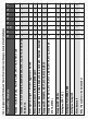
Other Transmitters / Andere Sender Hitec: Aurora 9 Multiplex: Cockpit SX Multiplex: Profi 3000, 4000 Multiplex: EVO 7,9,12 Graupner/JR: MX-24s Graupner: MC-10, MC-12, MC-14, MC-15, MC-16, MC-19, MC-22, MC-16/20, MX-12, MX-16s Graupner/JR: FM-6014, MC-17, MC-18, MC-20, MC-24 Graupner/JR: X-347, X-388, X-9303, MX-22, X-3810 ADT, PCM-10S, PCM-10X Hitec: Laser 4, Laser 6, Flash 5, Optic 6 sport Hitec: Optic 6, Eclipse 7, Prism 7, Aggressor CRX/SRX – – • – – – – – – – – • – – – – – – – – – – • • • •
Alarm Level Ant1: 9 Ant2: 9 Input Mode PPM standart Testing beeper on each alarm Button down starts test Sound test Rx Found Volt ACT/ALARM 10.0V / 8.5V - no signal 0 bad signal 9 the best signal minimal voltage actual voltage maximal voltage PPM standard PPM v2 (2x) PPM v3 (1.3) 0 to 9 actual voltage alarm voltage Duplex TX EX FW ver. 3.00 MeasureOrSetting Main Setting Rx: 0000 0000 Tx: 0000 0000 Rx Rx signal Level Ant1: 9 Ant2: 9 Volt Min/ACT/MAX 10.0/10.0/11.
Duplex Transmitter modules Receivers EN Series DUPLEX EX receivers are designated to operate with series DUPLEX and DUPLEX EX transmitter modules in the 2.4GHz band. Thanks to the full digital and bidirectional communication between transmitter and receiver they offer new chances in the field of remote controlled models. The DUPLEX EX transmitter modules and receivers take advantage of modern hightech technologies and offer thanks to precize production and test methods maximum safety and reliability.
Receivers EN Installation: Wrap the receiver with soft foam and position it as far as possible away of interference sources (servos, electric motors). Place the active ends of the antennas with an angle of 90° inbetween and as far away as possible of each other. The minimum bending radii of the antenna cables should not be smaller than 1 cm. The active parts of the antenna must remain straight and should be kept as far off as possible of metal parts.
5,2 (4,8) 2x100 (2x45) 8 (7) 1x200 (internal) 4 4,8 2x100 4 Weight [g] Antenna Length [mm] # of Channel Outputs JETIBOX NO 6 -98 JETIBOX NO 6 -98 Support Satellite Receiver Rsat Power Output [dBm] Receiver Sensitivity [dBm] Programming YES -98 6 NO JETIBOX YES -100 20 NO JETIBOX YES -98 6 NO JETIBOX YES 40 -98 6 NO JETIBOX YES 40 -106 20 NO JETIBOX YES 45 3.2 – 8.4 YES 45 3.2 – 8.4 Real Time Transmission of Telemetric Data 40 3.2 – 8.4 40 3.2 – 8.4 40 3.
R10 2x200 10 2x200 9 Antenna Length [mm] # of Channel Outputs 11 2x200 15 JETIBOX YES JETIBOX YES 20 -106 JETIBOX YES 20 -106 Support Satellite Receiver Rsat Power Output [dBm] Receiver Sensitivity [dBm] Programming YES YES Real Time Transmission of Telemetric Data -106 20 YES 30 30 30 Average Current [mA] 3.2 – 8.4 3.2 – 8.4 3.2 – 8.
Receivers EN Communication with the DUPLEX Receiver with aid of the JETIBOX The JETIBOX can be connected to the receiver in two ways: 1. By direct connection JETIBOX <-> receiver Plug the connector of the interconnecting cable (enclosed in the JETIBOX package) into the receptacle marked Impuls + - (positioned at the right side of the JETIBOX) and the other end into the receiver receptacle marked Ext.
Receivers EN RX/TX: Item RX shows the unic production number of the receiver. Item TX shows the unic production number of the transmitter, to which the receiver has eventually been paired. Rx Diag: Item A1 or A2 shows which antenna the receiver is using at present. Item Kx informs about the number of transferred channels (this number depends of the transmitter abilities).
Receivers EN -Signal fault: (valid for RSat and RMK) behaviour setup of the satellite receiver in case of signal loss. - Individual set: the behaviour of the output in case of a signal loss will be conducted by the setup of particulat channels in the menu Measurement/Setup – Setup of the output, where the behaviour of particular output channels in case of signal loss may be set – to repeating of the last deviation or to FailSafe.
Receivers EN - PPM Alarm Code: if one of the outputs SAT1/2 is set to PPM input mode, an acoustic signal can be set up which reports absence of the connected signal. By means of loading a morsealphabet character tones are set, which acoustically announce the absence of the PPM signal at the particular receiver input. These acoustic signals are generated by the transmitter module.
Receivers EN Auto Set – Normal = default setup, all received channels CH will be transferred without change to corresponding outputs Y, that means the receiver behaves lik a classical non programmable receiver.
Receivers EN 2. Elevon: both ailerons are controlled by independent servos on channels Y1 and Y2, move like standard ailerons on input CH1 (one up, second down) and at the same time like elevators on input CH2 (up/down simultaneously). In case of reverse sense of the mix change the sign in menu Mix Sign.
Receivers EN 5. Mix of elevator CH2 and flaps CH6: when flaps Y6 move, also elevator Y2 moves in opposite direction.
Receivers EN 8. Mix ailerons-flaps: both flaps and ailerons are on the wings. CH1 controls ailerons (Y1 and Y5), CH6 controls flaps (Y6 and Y7). Mixes ailerons so that they work also like flaps.
Receivers EN 10) Setup of different behaviour patterns of receiver outputs in case of transmitter signal loss. The throttle is affiliated with the receiver output channel Y3 and the other servos are connected to the remaining receiver outputs. In case of a signal loss we claim all servos to stop in their last positions and the motor must be switched off.
Receivers JETI BOX mini EN Button right Button down Button up Button left Button for switching input Ext.
Receivers EN Wiring Example of the receiver R18: Connection of receiver RSat to the input SAT1 of the receiver R18 The receiver RSat gets its current supply from receiver R18 and is paired with the transmitter module Tx. We recommend not to exceed a connection cable length of 2 meters between the receivers R18 and Rsat.
Receiver / Empfänger EN / DE Samples of output channels depending on inputs and receiver setup: Beispiele der Abhängigkeit der Ausgangskanäle vom Eingang und von der Empfängereinstellung:
Receiver / Empfänger EN / DE ELECTROSTATIC SENSITIVE DEVICE OBSERVE HANDLING PRECAUTIONS
Receiver / Empfänger 1 Default setup of the R14(1) and R18(2) receiver Output Groups (Production Setup) Einstellung der Ausgangsgruppen des Empfängers R14(1) und R18(2) ab Werk 2 EN / DE