
User manual

Duplex Transmitter modules
TX Modules of the DUPLEX system are offered as plug-in replacement modules DUPLEX TF and DUPLEX TG, as well as
internal assembly modules DUPLEX TA and DUPLEX TU2.
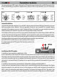
Installation of DUPLEX TF and DUPLEX TG Modules:
DUPLEX TF and TG modules are assigned to transmitters with exchangeable HF plug-in modules.
TF modules are compatible to corresponding exchangeable modules of Futaba and Hitec transmitters.
TG modules are assigned to Graupner and JR transmitters. Factual assignments see Table 2 at the end of
the instructions.
Remove the original HF module of your transmitter and plug-in with the correct orientation of the connector
the DUPLEX TF or TG in place of the original module. Screw the Tx-antenna delivered with the Tx module into
the module box.
Installation of the DUPLEX TU Module:
Place of destination of the DUPLEX TU2 transmitter modules are transmitters working in PPM mode, but
without having exchangeable HF module.
In this case connection of the module to the transmitter affords certain skill and experience with electronic
equipment. The skill necessary depends upon the type of transmitter and upon the manner you intend to connect it
up. On PPM transmitters with a „trainer“ connector the transmitter module can be connected to this connector. Other
transmitters require removal of the Tx back cover in order to assemble the module DUPLEX TU2 directly inside the
transmitter. For this kind of work we recommend to take advantage of the help of a service station. An acute list of
appropriate centers you may find on the home page of www.jetimodel.com.
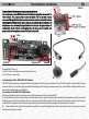
Installation with the Aid of the Trainer Connector:
Find the connections of the trainer connector in the instruction manual of your transmitter, connections of several
transmitters are shown below. In order to insure correct operation of the DUPLEX TU2 module jou have to interconnect
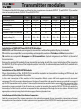
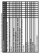
Table 1 Basic Data of TX Modules
Transmitter modules
EN
Basic data
DUPLEX
TU2
DUPLEX
TF
DUPLEX
TG2/TGi/TGi2/TGs
DUPLEX
TMe
DUPLEX
TMp
DUPLEX
TA
Dimensions [mm]
55x26x11
59x37x20
60x44x21
64x28x11
43x22x16
52x33x18
Weight [g]
15
40
50
17
20
10
Antenna [ ]dBi
2
2
2
2
2
2
Acoustic signalling
of conditions
•
•
•
•
•
•
Number of input PPM channels
16
16
16
16
16
9
Operation temperature [ ]°C
-10 to +85
-10 to +85
-10 to +85
-10 to +85
-10 to +85
-10 to +85
Supply voltage [V]
3,5 – 16
3,5 – 16
3,5 – 16
3,5 – 16
3,5 – 16
3,5 – 16
Average current [mA]
38
38
38
38
38
38
Output power [ ]dBm
20
20
20
20
20
20