
User manual

P - after switching on the transmitter has not yet been paired (did for the moment not
yet find a paired receiver)
S - there are no receiver data available (bad signal)
T - low voltage of the transmitter battery
B - low voltage of the receiver battery
I - there are no PPM pulses from the transmitter accessible (installation error, PCM
mode etc.)
Most of the conditions shown are accompanied by acoustic signals.
By pushing button U (upward arrow) range test mode may be activated.
ImpDiag – shows the actual number of transmitter PPM channels (K2 till K16, depends on transmitter type).
Volt MIN/ACT/MAX - minimum, actual and maximum value of transmitter module supply voltage. Reset („zeroing“)
of the min. and max. values is always executed when the transmitter is switched on and after location of the paired
receiver. Alternatively the displayed values may be reset by simultaneously pushing buttons L and R (left and right
arrow).
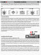
Rx Signal Level – shows the actual signal intensities of individual RX antennas. The intensity is shown in steps from 0
till 9 and the highest rating of 9 indicates the best reception of a particular antenna. A dash (-) indicates that the TX
module is not receiving any informations about the reception quality of the particular antenna. Either the receiver is
not connected or backward transmission from the receiver to the transmitter is at the range limit.
Volt ACT/ALARM – shows the actual value of transmitter module supply voltage and the adjusted limit for an alert
signal "T" (see menu Diag). By buttons L and R (JETIBOX buttons -left or right) the alert start limit may be adjusted.
Alarm Level – setting of the level, at which the transmitter module will start signalling low reception level of
receiver antennas. The lower line shows the actual level of the individual receiver antennas. If the reception with the
better signal level will fall below the set level, an acoustic sound will point out to this fact (2x short high-pitched
tones). See: RX Signal Level.
Input Mode – setting of the type of transmitter PPM input pulses. Most transmitters are using standard PPM signals.
You should choose PPM v2 or v3 only, if your transmitters allows switching to a different PPM mode. In most cases this
is related to transmitters with the ability of trasmitting more than 8 channels in PPM mode, as for instance 12 channel
Transmitters.
Alarm Error PPM – permission / prohibition of acoustic signalling of an unconnected or erroneous transmitter PPM
signal. Switching-off this type of signals is only recommended, if the module is used for telemetric purposes only and
is not connected to a transmitter used for model control.
EN
Transmitter modules