830CN/830CH/830CF USER'S MANUAL M/B For Socket-A Athlon/Duron Processor NO. G03-830CNR5A Release date: November 2001 Trademark: * Specifications and Information contained in this documentation are furnished for information use only, and are to change at any time without notice, and should not be construed as a commitment by manufacturer.
TABLE OF CONTENT USER’S NOTICE ............................................................................. 1 MANUAL REVISION INFORMATION ............................................. 2 THERMAL SOLUTIONS ................................................................... 2 CHAPTER 1 INTRODUCTION OF 830CN/830CH/830CF MOTHERBOARD 1-1 1-2 1-3 1-4 FEATURE OF MOTHERBOARD............................................................... 3 SPECIFICATION ..............................................................
-8 3-9 3-10 3-11 3-12 3-13 3-7-2 ONCHIP DEVICE FUNCTION ....................................................... 34 3-7-3 ONBOARD SUPERIO FUNCTION................................................. 35 POWER MANAGEMENT SETUP.............................................................. 36 3-8-1 PM WAKE UP EVENTS ................................................................... 37 PNP/PCI CONFIGURATION SETUP ........................................................ 38 3-9-1 IRQ RESOURCES .....................
USER’S NOTICE COPYRIGHT OF THIS MANUAL BELONGS TO THE MANUFACTURER. NO PART OF THIS MANUAL, INCLUDING THE PRODUCTS AND SOFTWARE DESCRIBED IN IT MAY BE REPRODUCED, TRANSMITTED OR TRANSLATED INTO ANY LANGUAGE IN ANY FORM OR BY ANY MEANS WITHOUT WRITTEN PERMISSION OF THE MANUFACTURER. THIS MANUAL CONTAINS ALL INFORMATION REQUIRED TO USE 830CN/830CH/ 830CF MOTHER-BOARD AND WE DO ASSURE THIS MANUAL MEETS USER’S REQUIREMENT BUT WILL CHANGE, CORRECT ANY TIME WITHOUT NOTICE.
Manual Revision Information Reversion 5.0 Revision History Fifth Edition Date November 2001 Item Checklist 5 830CN/830CH/830CF Motherboard 5 Cable for IDE/Floppy 5 CD for motherboard utilities □ 5 Cable for USB Port 3/4 (Option) 830CN/830CH/830CF User’s Manual AMD Athlon™ / Duron™ Processor Family Cooling Solutions As processor technology pushes to faster speeds and higher performance, thermal management becomes increasingly crucial when building computer systems.
Introduction of 830CN/830CH/830CF Motherboard 1-1 Feature of motherboard The 830CN/830CH/830CF motherboard is design for use AMD Athlon / Duron processors, which utilize the Socket A design and the memory size expandable to 1GB. This motherboard use the newest SiS 730S chipset, whose front side bus (133MHz/ 266MHz (DDR) for 830CH/830CF/830CN.
Design Chipset Clock Generator CPU Socket ∗ ∗ ∗ ∗ ∗ ∗ ∗ ∗ Micro ATX form factor 4 layers PCB size: 24.4x21.0cm SiS 730S Chipset for 830CN/830CH/830CF Support 100/133MHz Front Side Bus Clock (CPU Bus clock) Support 100/133MHz system memory clock Support 33MHz PCI Bus clock Support AMD Athlon 600MHz∼1.33GHz processor Support AMD Duron 600MHz∼850MHz processor Support 100/133 MHz CPU Bus clock Support 266MHz DDR (Double Data Rate) F.S.B.
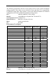
The following performance data list is the testing result of some popular benchmark testing programs. These data are just referred by users, and there is no responsibility for different testing data values gotten by users (the different Hardware & Software configuration will result in different benchmark testing results.
VGA Expansion Card: On Board VGA IBM DTLA-305040 (ATA-100) Hard Disk Driver: Award Optimal default BIOS: Win 98SE OS: Performance Test Report Share 8M Share 16M Share 32M 2446 2468 2466 3D Mark 99 1042 1082 1082 3D Mark 2000 644 653 654 3D Winbench 99 V1.2 22.2 27.3 29.8 3D Winbench 2000 9.28 6.29 6.29 Final Reality 32.6 33.5 32.3 Winstone 99 V1.3 39.4 40.9 37.2 Content Creation Winstone 2000 45.5 45.4 45.5 Content Creation Winstone 2001 39.2 39.2 39.
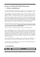
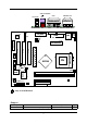
Only for 830CF PS/2 MOUSE USB PS/2 KEYBOARD COM1 GAME/MIDI PORT VGA LINE-OUT AUD_GAME U21 AUX_IN MIC_IN LINE_I U11 LINE_O MIC COM 1 PRINT PS/2 MOUSE & K/B USB PRN1 JP1 CD_IN2 LINE-IN KBMS VGA VIDEO AC97 CODEC PRINT LAN UL1 CD_IN ATX_PW PCI 1 PCI 2 PCI 3 CNR CNRSLOT ATX POWERCONN.
JP1 JBAT Keyboard Power ON Function Setting CMOS RAM Clear 3-pin Block 3-pin Block P.9 P.
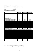
2-1 Hardware installation Steps Before using your computer, you had better complete the following steps: 1. Check motherboard setting 2. Install CPU 3. Install Memory 4. Install Expansion cards 5. Connect Ribbon cables, Panel wires, and power supply 6. Setup BIOS 7. Install software driver & utility 2-2 Checking Motherboard’s Jumper Setting 1. CPU Front Side Bus Frequency Setting (2-pin): S1 The motherboard’s CPU Host clock adjusted through jumper S1.
Note: You can clear CMOS by shorting 1-2 pin, while the system is unplug the power cord. Then return to 2-3 pin position. Avoid clearing the CMOS while the system is on, it will damage the motherboard. **Always unplug the power cord from the wall socket when clear CMOS.
Front Side Bus Frequency - the working frequency of the motherboard, which is generated by the clock generator for CPU, DRAM and PCI BUS. CPU L2 Cache - the flash memory inside the CPU, normally Athlon CPU has 256K or above, while Duron will have 64K. 2-3-2 About AMD Athlon & Duron 462-pin CPU This motherboard supports Socket-A (Socket-462) AMD Athlon/Duron processors. This motherboard provides a ZIF Socket-A.
WARNING! This section is for experienced motherboard installer only. Over clocking can result in system instability or even shortening life of the processor. After setting the Jumper S1 you can choose over clock running by BIOS CMOS SETUP UTILITY.
This motherboard provides two 168-pin DUAL INLINE MEMORY MODULES (DIMM) sites for memory expansion available from minimum memory size of 16MB to maximum memory size of 1GB SDRAM. Valid Memory Configurations Bank Bank 0, 1 (DIMM1) Bank 2, 3 (DIMM2) Total 168-Pin DIMM SDRAM 32, 64, 128, 256, 512MB X1 Total Memory 16MB∼512MB SDRAM 32, 64, 128, 256, 512MB X1 16MB∼512MB System Memory (Max.
WARNING! Turn off your power when adding or removing expansion cards or other system components. Failure to do so may cause severe damage to both your motherboard and expansion cards. 2-5-1 Procedure For Expansion Card Installation 1. Read the documentation for your expansion card and make any necessary hardware or software setting for your expansion card such as jumpers. 2. Remove your computer’s cover and the bracket plate on the slot you intend to use. 3. Align the card’s connectors and press firmly.
PCI slot 1 PCI slot 2 PCI slot 3 Onboard VGA AC97/MC97 Onboard USB Onboard USB 2 INT A INT B INT C INT D Shared Shared Shared Shared Shared Shared IMPORTANT! If using PCI cards on shared slots, make sure that the drivers support “Shared IRQ” or that the cards don’t need IRQ assignments. Conflicts will arise between the two PCI groups that will make the system unstable or cards inoperable.
(1) Power Connector: ATX_PW (20-pin block) ATX Power Supply connector. This is a new defined 20-pins connector that usually comes with ATX case. The ATX Power Supply allows to use soft power on momentary switch that connect from the front panel switch to 2-pins Power On jumper pole on the motherboard. When the power switch on the back of the ATX power supply turned on, the full power will not come into the system board until the front panel switch is momentarily pressed.
LAN (Only (5) for 830CF) Parallel Port Connector (25-pin female): PRINT Parallel Port connector is a 25-pin D-Subminiature Receptacle connector. The On-board Parallel Port can be disabled through the BIOS SETUP. Please refer to Chapter 3 “INTEGRATED PERIPHERALS SETUP” section for more detail information.
GAME/MIDI PORT LINE-OUT (8) LINE-IN MIC Serial Port COM1: COM1 COM1 is the 9-pin D-Subminiature mail connector. The On-board serial port can be disabled through BIOS SETUP. Please refer to Chapter 3 “INTEGRATED PERIPHERALS SETUP” section for more detail information. COM1 (9) Floppy drive Connector (34-pin block): FDD This connector supports the provided floppy drive ribbon cable. After connecting the single plug end to motherboard, connect the two plugs at other end to the floppy drives.
Pin 1 Primary IDE Connector (11) Secondary IDE Connector (40-pin block): IDE2 This connector connects to the next set of Master and Slave hard disks. Follow the same procedure described for the primary IDE connector. You may also configure two hard disks to be both Masters using one ribbon cable on the primary IDE connector and another ribbon cable on the secondary IDE connector. Secondary IDE Connector Pin 1 • • Two hard disks can be connected to each connector.
These headers are used for connecting the additional USB port plug. By attaching an option USB cable, your can be provided with two additional USB plugs affixed to the back panel. Pin 1 USB1 VCC − DATA +DATA GND VCC − DATA +DATA GND NC USB Port Headers (3) IDE Activity LED: IDE LED This connector connects to the hard disk activity indicator light on the case. (4) Turbo LED switch: TURBO LED Since the motherboard’s turbo function is always on.
This connector connects to a LAN card with a WAKE ON-LAN output. This connector power up the system when a wake up signal is received through the LAN card. NOTE: This feature requires that Wake On LAN or Ring In Wake up is enabled. WOL 1 5VSB GND WON 3 Wake-On-LAN Headers (10) FAN Speed Headers (3-pin): CPUFAN, SYSFAN These connectors support cooling fans of 350mA (4.2 Watts) or less, depending on the fan manufacturer, the wire and plug may be different.
1 4 1 4 CD_IN2 CD_IN CD Audio-In Headers (13) AUX-In Headers (4-pin): AUX_IN AUX_IN 4 1 AUX In Headers (14) Audio External Connector (9-pin): AUDIO AUDIO Pin 1 L-IN-L GND MIC L-IN-R GND MICP GND L-OUT-R L-OUT-L Audio External Connector 22
2-7 Starting Up Your Computer 1. After all connection are made, close your computer case cover. 2. Be sure all the switch are off, and check that the power supply input voltage is set to proper position, usually in-put voltage is 220V∼240V or 110V∼120V depending on your country’s voltage used. 3. Connect the power supply cord into the power supply located on the back of your system case according to your system user’s manual. 4. Turn on your peripheral as following order: a. Your monitor. b.
Chapter 3 Introducing BIOS The BIOS is a program located on a Flash Memory on the motherboard. This program is a bridge between motherboard and operating system. When you start the computer, the BIOS program gain control. The BIOS first operates an auto-diagnostic test called POST (power on self test) for all the necessary hardware, it detects the entire hardware device and configures the parameters of the hardware synchronization.
Main Menu The on-line description of the highlighted setup function is displayed at the bottom of the screen. Status Page Setup Menu/Option Page Setup Menu Press F1 to pop up a small help window that describes the appropriate keys to use and the possible selections for the highlighted item. To exit the Help Window, press . 3-3 The Main Menu Once you enter Award BIOS CMOS Setup Utility, the Main Menu (Figure 3-1) will appear on the screen.
Power Management Setup Use this menu to specify your settings for power management. PnP/PCI configurations This entry appears if your system supports PnP/PCI. PC Health Status This entry shows your PC health status. Miscellaneous Control Use this menu to specify your settings for Miscellaneous control. Load Optimized Defaults Use this menu to load the BIOS default values that are factory settings for optimal performances system operations.
> > > > IDE IDE IDE IDE Primary Master Primary Slave Secondary Master Secondary Slave Press Press Press Press Enter Enter Enter Enter None None None None Drive A Drive B 1.44M, 3.25 in.
Anti-Virus Protection PhoenixNet Support CPU L1 Cache CPU L2 Cache Quick Power On Self Test First Boot Device Second Boot Device Third Boot Device Boot Other Device Swap Floppy Drive Boot Up Floppy Seek Boot Up NumLock Status Gate A20 Option Typematic Rate Setting Typematic Rate (Chars/Sec) Typematic Delay (Msec) Security Option OS Select For DRAM > 64MB HDD S.M.A.R.T.
The BIOS attempts to load the operating system from the devices in the sequence selected in these items. The settings are Floppy, LS/ZIP, HDD-0/HDD-1/HDD-3, SCSI, CDROM, LAN and Disabled. Swap Floppy Drive Switches the floppy disk drives between being designated as A and B. Default is Disabled. Boot Up Floppy Seek During POST, BIOS will determine if the floppy disk drive installed is 40 or 80 tracks. 360K type is 40 tracks while 760K, 1.2M and 1.44M are all 80 tracks.
CMOS Setup Utility – Copyright(C) 1984-2000 Award Software Advanced Chipset Features DRAM Timing Settings AGP Function Settings PCI GRANT Parking on Memory Parity Check System BIOS Cacheable Video RAM Cacheable Memory Hole at 15M-16M System Share Memory Size Press Enter Press Enter PMR Disabled Disabled Disabled Disabled 8MB Item Help Menu Level > ↑↓→← Move Enter:Select Item +/-/PU/PD:Value F10:Save ESC:Exit F1:General Help F5:Previous Values F6:Optimized Defaults F7:Standard Defaults DRAM Timing Settin
system memory usually discusses their memory requirements. The settings are: Enabled and Disabled.
CMOS Setup Utility – Copyright(C) 1984-2000 Award Software AGP Function Settings AGP Aperture Size AGP Driving Control AGP Driving Value 64MB Auto 88 Item Help ← (Only for 830CH/CF) ↑↓→← Move Enter:Select Item +/-/PU/PD:Value F10:Save ESC:Exit F1:General Help F5:Previous Values F6:Optimized Defaults F7:Standard Defaults 3-7 Integrated Peripherals CMOS Setup Utility – Copyright(C) 1984-2000 Award Software Integrated Peripherals > OnChip IDE Function > OnChip Device Function > Onboard SuperIO Function In
CMOS Setup Utility – Copyright(C) 1984-2000 Award Software OnChip IDE Function Internal PCI/IDE Primary Master PIO Primary Slave PIO Secondary Master PIO Secondary Slave PIO Primary Master UDMA Primary Slave UDMA Secondary Master UDMA Secondary Slave UDMA IDE Burst Mode IDE HDD Block Mode IDE Prefetch Mode Delay For HDD (Secs) Both Auto Auto Auto Auto Auto Auto Auto Auto Enabled Enabled Enabled 0 Item Help Menu Level >> ↑↓→← Move Enter:Select Item +/-/PU/PD:Value F10:Save ESC:Exit F1:General Help F5:Prev
AC97 Audio Device Game Port Address Midi Port Address Midi Port IRQ AC97 Modem Device ETHERNET Function ETHERNET Address IDE Input Current ETHERNET Address is USB Controller USB Keyboard Legacy Support Enabled 201 Disabled 10 Enabled Enabled Press Enter 003018-XXXXXX Enabled Disabled Item Help Menu Level >> ← (Only for 830CF) ↑↓→← Move Enter:Select Item +/-/PU/PD:Value F10:Save ESC:Exit F1:General Help F5:Previous Values F6:Optimized Defaults F7:Standard Defaults AC97 Sound Device This item allows you
Onboard FDD Controller Onboard Serial Port 1 Onboard Serial Port 2 UART2 Mode RxD,TxD Active IR Transmission Delay IR Duplex Mode Use IR Pins Onboard Parallel Port Parallel Port Mode EPP Mode Select ECP Mode Use DMA Enabled 3F8/IRQ4 2F8/IRQ3 Normal Hi, Lo Enabled Half IRRX/IRTX 378/IRQ7 SPP EPP1.
The Power Management Setup allows you to configure your system to most effectively save energy saving while operating in a manner consistent with your own style of computer use.
CMOS Setup Utility – Copyright(C) 1984-2000 Award Software PM Wake Up Events IRQ [3-7,9-15],NMI IRQ 8 Break Suspend RING Power Up Control MACPME Power UP Control PCIPME Power Up Control KB Power ON Password Power Up by Alarm x Month Alarm x Day of Month Alarm x Time (hh:mm:ss) Alarm Enabled Disabled Disabled Disabled Disabled Enter Disabled NA NA 0 : 0 : 0 Item Help Menu Level >> ↑↓→← Move Enter:Select Item +/-/PU/PD:Value F10:Save ESC:Exit F5:Previous Values F1:General Help F6:Optimized Defaults F7:St
This section describes configuring the PCI bus system. PCI, or Personal Computer Interconnect, is a system which allows I/O devices to operate at speeds nearing the speed the CPU itself uses when communicating with its own special components. This section covers some very technical items and it is strongly recommended that only experienced users should make any changes to the default settings.
CMOS Setup Utility – Copyright(C) 1984-2000 Award Software IRQ Resources IRQ-3 IRQ-4 IRQ-5 IRQ-7 IRQ-9 IRQ-10 IRQ-11 IRQ-12 assigned assigned assigned assigned assigned assigned assigned assigned to to to to to to to to PCI PCI PCI PCI PCI PCI PCI PCI Device Device Device Device Device Device Device Device Item Help Menu Level >> Legacy ISA for devices Compliant with the Original PC AT bus Specification, PCI/ISA PnP for devices Compliant with the Plug and Play standard Whether designed for PCI or ISA b
This section is for setting CPU Frequency Control.
You can set either supervisor or user password, or both of them. The differences are: Supervisor password: User password: Can enter and change the options of the setup menus. Can only enter but do not have the right to change the options of the setup menus. When you select this function, the following message will appear at the center of the screen to assist you in creating a password. ENTER PASSWORD: Type the password, up to eight characters in length, and press .
DRIVER & FREE PROGRAM INSTALLATION Check your package and there is A MAGIC INSTALL CD included. This CD consists of all DRIVERS you need and some free application programs and utility programs. In addition, this CD also include an auto detect software which can tell you which hardware is installed, and which DRIVERS needed so that your system can function properly. We call this auto detect software MAGIC INSTALL. MAGIC INSTALL supports WINDOWS 95/98/98SE/ME/NT4.
Require. (Only for 830CH/830CF) The path of the file: for WINDOWS 9X is X:\SIS630\AGPVXD\WIN9X\SETUP.EXE (including WIN95/98/98SE/ME) for WINDOWS 2000 is X:\SIS630\AGPVXD\WIN2000\SETUP.EXE For WINDOWS 95/98/98SE/ME/2000 1. Click AGPVXD when Magic Install MENU appears 2. Click Next when SiS Aceleration Graphic Port appears 3. Click NEXT or choose BROWSE to change the path For the file to be stored 4.
for WINDOWS 9X is X:\SIS630\VGA\WIN9X\SETUP.EXE (including Windows 98/98SE/ME) for WINDOWS NT4.0 is X:\SIS630\VGA\WINNT40 for WINDOWS 2000 is X:\SIS630\VGA\WIN2000\SETUP.EXE for LINUX is X:\SIS630\LINUX A. For WINDOWS 98/98SE/ME/2000 5. Click VGA when Magic Install MENU appears 6. 7. Multimedia Package support three types of Setup: Typical, Compact, Custom 8. System will add program icons to the Program Folder listed.
9. System starting install VGA driver 4-3 SOUND 10. After Setup complete please select restart my computer now and click Finish to complete setup Install SiS 7018 AC’97 Audio Driver and Application Software The path of the file is X:\SIS630\SOUND\SETUP.EXE (Support WINDOWS 95/98/98SE/ME/NT4.0/2000) 1. Click SOUND when Magic Install Menu window appears 2.
3. Click Next to install the driver in Program 4. Select restart my computer now and click Files Folder Finish to complete setup 5. After restart computer the system will auto 6. Click Audio Rack when Magic Install detect SiS 7018 Audio Driver and install it Menu appears to system 7.
4-4 LAN (Only for 830CF) Install SiS 900 PCI Fast Ethernet Driver The path of the file: for WINDOWS 9X/2000 is X:\SIS630\LANDRV\SETUP.EXE (Including WINDOWS 95/98/98SE/98ME/2000) for WINDOWS NT4.0 is X:\SIS630\LANDRV\NT40 WINDOWS 95/98/98SE/98ME/2000 Setup 1. Click LAN when Magic Install Menu appears 2. Click NEXT when SiS PCI LAN Driver Setup appears 3. Choice restart my computer now to finish 4.
4-5 LANLED Install SiS 900 LAN State Utility 1. Click LANLED when Magic Install Menu appears 2. 3. “SiS 10/100 Fast Ethernet Monitor” can real time Monitor your LAN status Run Programs\Lanled will show Next Screen 4-6 PC-HEALTH Winbond Hardware Doctor Monitoring Software The path of the file is X:\SIS630\HEALTH-W\SETUP.
appears 3. Click the Button to start installation Setup Window appears 4. Select Program Group name or enter a new group name, click continue to setup and click OK after setup complete 4-6-1 How To Utilize PC-HEALTH 2. After executing Winbond Hardware 1. Click Program → Winbond Hardware Doctor it supports system voltage, Fan Doctor → Hardware Doctor the Winbond speed and CPU/SYSTEM Temperature.
4-7 MAGIC BIOS Install BIOS Live Update Utility 1. Click Magic BIOS when Magic Install MENU appears 2. Click Next to install the Magic BIOS in Destination Folder 3. After finish Setup you will have a Magic BIOS icon in your screen 4. Double click the Magic BIOS icon you will have this picture, choose from internet you can upgrade BIOS On-line 5. When On-line update BIOS the program will auto-check your BIOS version 6.
and automatically restart 7. Click Yes if you want to update the BIOS otherwise choose No to exit 8. When System programming BIOS don’t turn off power, after finish update BIOS, the system will clear CMOS and automatically Restart 9. When choose From Local Driver to update BIOS, you must have the correct BIOS file in your Local Driver 10. Choose the correct BIOS file to update BIOS 4-8 PC-CILLIN Install PC-CILLIN 2000 Anti-virus program 1. Click PC-CILLIN when MAGIC INSTALL MENU Appears 2.
is starting to detect HD for virus 3. Click NEXT and Enter User Information, Click NEXT or choose BROWSE to change the path For the file to be stored 4. Click NEXT and Choose all Internet Protection 5. Click OK and If You Have Proxy Server, Enter Your Setting. 6. Click NEXT when Start Copy Files, Start to install the software. 7. If you want to make a rescue disc, insert a 1.44 MB disc 8.
9. Enter Your name and E-mail address Register PC-cillin 2000 or Click Cancel Register Later 10. After install PC-cillin 2000 complete we recommend select update item to download newest virus code and setting Auto refresh virus code 4-9 How To Disable On Board Sound Function Please key in “DEL” key after power on to enter BIOS SETUP screen and choose Integrate Peripherals → On-Chip Device Function → AC97 Audio item to disabled all on board Sound function by Page Down key. 4-10 HOW TO UPDATE BIOS STEP 1.