845CA/845CAL USER'S MANUAL M/B For Socket 478 Pentium 4 Processor NO. G03-845CAR1A Release date: January 2002 Trademark: * Specifications and Information contained in this documentation are furnished for information use only, and are subject to change at any time without notice, and should not be construed as a commitment by manufacturer.
TABLE OF CONTENT USER’S NOTICE ................................................................................ ii MANUAL REVISION INFORMATION .............................................. 1 COOLING SOLUTIONS ................................................................... 1 CHAPTER 1 INTRODUCTION OF 845CA/845CAL MOTHERBOARD 1-1 1-2 1-3 1-4 FEATURE OF MOTHERBOARD ............................................... 2 SPECIFICATION ....................................................................
-10 3-11 3-12 3-13 PC HEALTH STATUS ............................................................. 36 MISCELLANEOUS CONTROL................................................. 37 LOAD STANDARD/OPTIMIZED DEFAULTS ............................. 38 SET SUPERVISOR/USER PASSWORD ...................................... 38 CHAPTER 4 DRIVER & FREE PROGRAM INSTALLATION MAGIC INSTALL SUPPORTS WINDOWS 95/98/98SE/NT4.0/2000 ......... 39 4-1 INF INSTALL INTEL 845 CHIPSET SYSTEM DRIVER ............
Manual Revision Information Reversion 1.0 Revision History First Release Date January 2002 Item Checklist □ 845CA/845CAL Cable for IDE/Floppy CD for motherboard utilities Cable for USB Port 3/4 (Option) 845CA/845CAL User’s Manual Intel Pentium 4 Processor Family Cooling Solutions As processor technology pushes to faster speeds and higher performance, thermal management becomes increasingly crucial when building computer systems.
Chapter 1 Introduction of 845CA/845CAL Motherboard 1-1 Feature of motherboard The 845CA/845CAL motherboard is design for use Intel Pentium 4 Processor in 478 Pin Package/Northwood Processor with the Intel 845 Chipset delivers a high performance and professional desktop platform solution. Which utilize the Socket 478 design and the memory size expandable to 3.0GB.
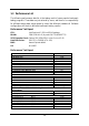
1-2 Specification Spec Design Chipset CPU Socket (mPGA478B Socket) Memory Socket Expansion Slot & Headers Integrate IDE LAN On Board (Only for 845CAL) Audio BIOS Multi I/O Description ∗ ∗ ∗ ∗ ∗ ∗ ∗ ∗ ∗ ∗ ∗ ∗ ∗ ∗ ∗ ∗ ∗ ∗ ∗ ∗ ∗ ∗ ∗ ∗ ∗ ∗ ATX form factor 4 layers PCB size: 30.5x21.0cm Intel 845 Memory Controller Hub (MCH) Chipset Intel 82801BA I/O Controller Hub (ICH2) Chipset Support Intel Pentium 4 478 Pin package utilizes FlipChip Pin Grid Array (FC-PGA2) package processor Support 1.5G∼2.
1-3 Performance List The following performance data list is the testing result of some popular benchmark testing programs. These data are just referred by users, and there is no responsibility for different testing data values gotten by users (the different Hardware & Software configuration will result in different benchmark testing results.) Performance Test Report CPU: Intel Pentium 4 1.
1-4 Layout Diagram & Jumper Setting LAN PRINT GAME/MIDI PORT PS/2 MOUSE PS/2 Keyboard USB COM1 COM2 MIC LINE-IN LINE-OUT ATX 12V Power Conn. PS2 KB/Mouse Port CPU Socket CPU FAN USB Port /LAN Connector (for 845CAL) ATX Power Conn. PC133 DIMMX3 ATX P6 Power Conn. PC99 Back Panel Intel 845 Chip ATA 100 IDE Conn.
Jumpers Jumper JP10 Name CMOS RAM Clear Description 3-pin Block Page P.
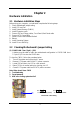
Chapter 2 Hardware installation 2-1 Hardware installation Steps Before using your computer, you had better complete the following steps: 1. Check motherboard jumper setting 2. Install CPU and Fan 3. Install System Memory (DIMM) 4. Install Expansion cards 5. Connect IDE and Floppy cables, Front Panel /Back Panel cable 6. Connect ATX Power cable 7. Power-On and Load Standard Default 8. Reboot 9. Install Operating System 10.
2-3 Install CPU 2-3-1 Glossary Chipset (or core logic) - two or more integrated circuits which control the interfaces between the system processor, RAM, I/O devises, and adapter cards. Processor slot/socket - the slot or socket used to mount the system processor on the motherboard. Slot (AGP, PCI, ISA, RAM) - the slots used to mount adapter cards and system RAM. AGP - Accelerated Graphics Port - a high speed interface for video cards; runs at 1X (66MHz), 2X (133MHz), or 4X (266MHz).
2-3-2 About Intel Pentium 4 478-pin CPU This motherboard provides a 478-pin surface mount, Zero Insertion Force (ZIF) socket, referred to as the mPGA478B socket supports Intel Pentium 4 processor in the 478 Pin package utilizes Flip-Chip Pin Grid Array (FC-PGA2) package technology. The CPU that comes with the motherboard should have a cooling FAN attached to prevent overheating. If this is not the case, then purchase a correct cooling FAN before you turn on your system.
2-4 Install Memory This motherboard provides three 168-pin DUAL INLINE MEMORY MODULES (DIMM) sites for memory expansion available from minimum memory size of 64MB to maximum memory size of 3.0GB SDR SDRAM. Valid Memory Configurations Bank 168-Pin DIMM Total Memory Bank 0, 1 (DIMM1) PC133 SDR SDRAM Module X1 64MB∼1.0GB Bank 2, 3 (DIMM2) PC133 SDR SDRAM Module X1 64MB∼1.0GB Bank 4, 5 (DIMM3) PC133 SDR SDRAM Module X1 64MB∼1.0GB Total System Memory (Max. 3.0GB) 3 64MB∼3.
2-5 Expansion Cards WARNING! Turn off your power when adding or removing expansion cards or other system components. Failure to do so may cause severe damage to both your motherboard and expansion cards. 2-5-1 Procedure For Expansion Card Installation 1. Read the documentation for your expansion card and make any necessary hardware or software setting for your expansion card such as jumpers. 2. Remove your computer’s cover and the bracket plate on the slot you intend to use. 3.
* These IRQs are usually available for ISA or PCI devices. 2-5-3 Interrupt Request Table For This Motherboard Interrupt request are shared as shown the table below: Slot 1 Slot 2 Slot 3 Slot 4 Slot 5 Slot 6 Onboard VGA Onboard USB 1 Onboard USB 2 AC97/MC97 INT A INT B INT C INT D INT E INT F INT G INT H √ √ √ √ √ √ √ √ √ IMPORTANT! If using PCI cards on shared slots, make sure that the drivers support “Shared IRQ” or that the cards don’t need IRQ assignments.
Example 1: SiS 305 & ATi Rage 128 Pro AGP card those golden finger is compatible with 2X/4X mode AGP slot, but only can support 2X (3.3V) only. If you install these cards in Intel® 845 based motherboard it will burn and damage the motherboard. Example 2: We also find Diamond Vipper V770 golden finger is design for 2X/4X mode AGP Slot. It can be adjusted the jumper for AGP 2X (3.3V) or AGP 4X (1.5V). But the factory default setting is 2X (3.3V).
Pin 1 (3) ATX P6 Power Connector (6-pin block) : ATXP9 This is a new defined 6-pins connector that usually comes with ATX Power Supply. The ATX Power Supply which fully support Pentium 4 processor must including this connector for support extra 3.3V and 5V voltage to maintain system power consumption. Without this connector might cause system unstable because the power supply can not provide sufficient current for system. GND BLK GND GND 3.3V BLK 3.
(9) Serial Port COM1, COM2 : COM1, COM2 COM1, COM2 are the 9-pin D-Subminiature mail connector. The On-board serial port can be disabled through BIOS SETUP. Please refer to Chapter 3 “INTEGRATED PERIPHERALS SETUP” section for more detail information. PS/2 MOUSE LAN PRINT GAME/MIDI PORT MIC PS/2 Keyboard USB LINE-IN COM1 COM2 LINE-OUT (10) Floppy drive Connector (34-pin block): FDD This connector supports the provided floppy drive ribbon cable.
(12) Secondary IDE Connector (40-pin block): IDE2 This connector connects to the next set of Master and Slave hard disks. Follow the same procedure described for the primary IDE connector. You may also configure two hard disks to be both Masters using one ribbon cable on the primary IDE connector and another ribbon cable on the secondary IDE connector. Pin 1 Secondary IDE Connector • Two hard disks can be connected to each connector.
VCC -DATA +DATA GND +DATA GND GND USB1 VCC USB Port Headers (9-pin) : USB1 These headers are used for connecting the additional USB port plug. By attaching an option USB cable, your can be provided with two additional USB plugs affixed to the back panel. -DATA (2) Pin 1 USB Port Headers (3) IDE Activity LED: IDE LED This connector connects to the hard disk activity indicator light on the case. (4) Turbo LED switch: TURBO LED Since the motherboard’s turbo function is always on.
Power LED GND NC VCC VCC GND Turbo SW/ SMI Keyboard Lock GND GND IDELED Turbo LED Reset SW VCC NC GND Speaker GND PWR BTN System Case Connections (9) Wake On-LAN/Modem Headers (3-pin) : WOL, WOM This connector connects to a LAN/Modem card with a WAKE ON-LAN/Modem output. This connector power up the system when a wake up signal is received through the LAN/Modem card. WOL 5VSB GND WOM 5VSB GND WON NOTE: This feature requires that Wake On LAN or Ring In Wake up is enabled.
(11) IR infrared module Headers (5-pin) : IR This connector supports the optional wireless transmitting and receiving infrared module. You must configure the setting through the BIOS setup to use the IR function. 5 1 IRTX VCC IRRX GND IR Infrared Module Headers (12) CD Audio-In Headers (4-pin) : CDIN CDIN are the connectors for CD-Audio Input signal. Please connect it to CD-ROM CD-Audio output connector.
2-7 Starting Up Your Computer 1. After all connection are made, close your computer case cover. 2. Be sure all the switch are off, and check that the power supply input voltage is set to proper position, usually in-put voltage is 220V∼240V or 110V∼120V depending on your country’s voltage used. 3. Connect the power supply cord into the power supply located on the back of your system case according to your system user’s manual. 4. Turn on your peripheral as following order: a. Your monitor. b.
Chapter 3 Introducing BIOS The BIOS is a program located on a Flash Memory on the motherboard. This program is a bridge between motherboard and operating system. When you start the computer, the BIOS program gain control. The BIOS first operates an auto-diagnostic test called POST (power on self test) for all the necessary hardware, it detects the entire hardware device and configures the parameters of the hardware synchronization.
3-2 Getting Help Main Menu The on-line description of the highlighted setup function is displayed at the bottom of the screen. Status Page Setup Menu/Option Page Setup Menu Press F1 to pop up a small help window that describes the appropriate keys to use and the possible selections for the highlighted item. To exit the Help Window, press . 3-3 The Main Menu Once you enter Award BIOS CMOS Setup Utility, the Main Menu (Figure 3-1) will appear on the screen.
Integrated Peripherals Use this menu to specify your settings for integrated peripherals. Power Management Setup Use this menu to specify your settings for power management. PnP/PCI configurations This entry appears if your system supports PnP/PCI. PC Health Status This entry shows your PC health status. Miscellaneous Control Use this menu to specify your settings for Miscellaneous control.
CMOS Setup Utility – Copyright(C) 1984-2001 Award Software Standard CMOS Features > > > > Date (mm:dd:yy) Time (hh:mm:ss) Thu, Jul, 05 2001 11 : 33 : 50 IDE IDE IDE IDE Press Press Press Press Primary Master Primary Slave Secondary Master Secondary Slave Enter Enter Enter Enter None None None None Drive A Drive B 1.44M, 3.25 in.
3-5 Advanced BIOS Features CMOS Setup Utility – Copyright(C) 1984-2001 Award Software Advanced BIOS Features Anti-Virus Protection Recovery Genius Hard Disk Boot Priority CPU L1 &L2 Cache Quick Power On Self Test Hard Disk Boot Priority First Boot Device Second Boot Device Third Boot Device Boot other Device Swap Floppy Drive Boot Up Floppy Seek Boot Up NumLock Status Gate A20 Option Typematic Rate Setting Typematic Rate (Chars/Sec) Typematic Delay (Msec) Security Option APIC Mode MPS Version Control For OS
Quick Power On Self-Test This category speeds up Power On Self Test (POST) after you power on the computer. If this is set to Enabled. BIOS will shorten or skip some check items during POST. Enabled (default) Enable quick POST Disabled Normal POST First/Second/Third/Fourth Boot Device The BIOS attempts to load the operating system from the devices in the sequence selected in these items. The settings are Floppy, LS/ZIP, HDD-0/HDD-1/HDD-3, SCSI, CDROM, LAD and Disabled.
3-6 Advanced Chipset Features The Advanced Chipset Features Setup option is used to change the values of the chipset registers. These registers control most of the system options in the computer.
3-6-1 DRAM Timing Settings CMOS Setup Utility – Copyright(C) 1984-2001 Award Software DRAM Timing Settings Auto Configuration SDRAM CAS Latency Time SDRAM Cycle Time SDRAM RAS# to CAS# Delay SDRAM RAS# Precharge Standard 3 7 3 3 Item Help Menu Level >> ↑↓→← Move Enter:Select +/-/PU/PD:Value F10:Save ESC:Exit F1:General Help F5:Previous Values F6:Optimized Defaults F7:Standard Defaults SDRAM RAS# To CAS# Delay This field let’s you insert a timing delay between the CAS and RAS strobe signals, used when D
Onboard IDE Function Please refer to section 3-7-1 Onboard Device Function Please refer to section 3-7-2 Onboard Super IO Function Please refer to section 3-7-3 Init Display First This item allows you to decide to activate whether PCI Slot or AGP VGA first. The settings are: PCI Slot, AGP Slot.
IDE HDD Block Mode Block mode is also called block transfer, multiple commands, or multiple sector read/write. If your IDE hard drive supports block mode (most new drives do), select Enabled for automatic detection of the optimal number of block read/writes per sector the drive can support. The settings are: Enabled, Disabled.
3-7-3 Onboard Super IO Function CMOS Setup Utility – Copyright(C) 1984-2001 Award Software Onboard Super IO Function Onboard FDD Controller Onboard Serial Port 1 Onboard Serial Port 2 UART2 Mode RxD, TxD Active IR Duplex Mode Use IR Pins Onboard Parallel Port Parallel Mode EPP Mode Select ECP Mode Use DMA Enabled 3F8/IRQ4 2F8/IRQ3 Normal Hi, Lo Half IRRX/IRTX 378/IRQ7 SPP EPP1.
SPP/EPP/ECP/ECP+EPP To operate the onboard parallel port as Standard Parallel Port only, choose “SPP.” To operate the onboard parallel port in the EPP modes simultaneously, choose “EPP.” By choosing “ECP”, the onboard parallel port will operate in ECP mode only. Choosing “ECP+EPP” will allow the onboard parallel port to support both the ECP and EPP modes simultaneously. The ECP mode has to use the DMA channel, so choose the onboard parallel port with the ECP feature.
Video Off in Suspend This determines the manner in which the monitor is blanked. The choice are Yes → Video will off , and No→ Video always On. Video Off Method This determines the manner in which the monitor is blanked. DPMS (default) Initial display power management signaling. Blank Screen This option only writes blanks to the video buffer. V/H SYNC+Blank This selection will cause the system to turn off the vertical and horizontal synchronization ports and write blanks to the video buffer.
3-8-1 PM Timer Reload Events CMOS Setup Utility – Copyright(C) 1984-2001 Award Software PM Timer Reload Events Primary IDE 0 Primary IDE 1 Secondary IDE 0 Secondary IDE 1 FDD, COM, LPT Port PCI PIRQ [A-D] # Disabled Disabled Disabled Disabled Disabled Disabled Item Help Menu Level >> ↑↓→← Move Enter:Select +/-/PU/PD:Value F10:Save ESC:Exit F5:Previous Values F6:Optimized Defaults F1:General Help F7:Standard Defaults 3-9 PnP/PCI Configuration Setup This section describes configuring the PCI bus syste
Reset Configuration Data Normally, you leave this field Disabled. Select Enabled to reset Extended System Configuration Data (ESCD) when you exit Setup if you have installed a new add-on and the system reconfiguration has caused such a serious conflict that the operating system can not boot. The settings are: Enabled and Disabled. Resource Controlled By The Award Plug and Play BIOS has the capacity to automatically configure all of the boot and Plug and Play compatible devices.
3-10 PC Health Status This section shows the Status of you CPU, Fan, Warning for overall system status. This is only available if there is Hardware Monitor onboard. CMOS Setup Utility – Copyright(C) 1984-2001 Award Software PC Health Status Shutdown Temperature CPU Warning Temperature Show PC Health in Post Current System Temperature Current CPU Temperature Current CPUFAN Speed Current SYSFAN Speed Current SYSFAN2 Speed Vcore Vcc1.5 Vcc3.
3-11 Miscellaneous Control This section is for setting CPU Frequency/Voltage Control. CMOS Setup Utility – Copyright(C) 1984-2001 Award Software Miscellaneous Control CPU Clock Ratio Auto Detect PCI Clk Spread Spectrum ** Current Host Clock is 100/33MHz HOST/PCI Clock at Next Boot is ** Current DRAM Clock is 133MHz ** DRAM Clock at Next Boot is PCI Clock Ratio Vcc1.5 Select Flash Part Write Protect X 8 Enabled Disabled ** 100/33MHz Item Help Menu Level > 133MHz Host/3 1.
3-12 Load Standard/Optimized Defaults Load Standard Defaults When you press on this item, you get confirmation dialog box with a message similar to: Load Standard Defaults (Y/N)? N Pressing loads the BIOS default values for the most stable, minimal-performance system operations.
Chapter 4 DRIVER & FREE PROGRAM INSTALLATION Check your package and there is A MAGIC INSTALL CD included. This CD consists of all DRIVERS you need and some free application programs and utility programs. In addition, this CD also include an auto detect software which can tell you which hardware is installed, and which DRIVERS needed so that your system can function properly. We call this auto detect software MAGIC INSTALL. MAGIC INSTALL Supports WINDOWS 95/98/98SE/ME/NT4.
4-1 INF install INTEL 845 chipset system driver After you have completed the installation of your operation system (WINDOWS 95/98/ 98SE). You will find an UNKNOWN DEVICE in the device manager (START/SETTING/ CONTROL PANEL/SYSTEM/DEVICE MANAGER). You have to install INF driver as shown below: 1. Click INF in the MAGIC INSTALL MENU 2. Click NEXT when Chipset Software Install Utility appears 3. This chart shows motherboards supported 4.
4-2 SOUND Install ALC201 Audio Codec Driver 1. Click SOUND when MAGIC INSTALL MENU appears 2. Then auto detect operation system language edition, click Next, start to install DRIVER 3. Click Finish and Restart Windows 4. Click Start→Program→Avance Sound Manager→AvRack. Then AVRACK Windows appears 5. Avance Audio Rack table can play CD, WAV, MID, MP3, AVI, MPG Format File 6.
4-3 LAN Install RTL8100 LAN Controller Driver The path of the file: for WINDOWS 95OSR2 is X:\RTLLAN\W95OSR2 for WINDOWS 98/98SE is X:\RTLLAN\WIN98 for WINDOWS 98ME is X:\RTLLAN\WIN98ME for WINDOWS NT4.0 is X:\RTLLAN\WINNT4 for WINDOWS 2000 is X:\RTLLAN\WIN2000 WINDOWS 95/98/98SE/98ME/2000/XP Setup 1. Click LAN when Magic Install Menu appears 2. Click NEXT when Realtak PCI LAN Driver Setup appears 3. Driver install Finish, Click YES, restart the computer 4.
4-4 PC-HEALTH Intel 845 PC-Health Monitor The path of the file is X:\INTEL845\HW30\SETUP.EXE (Only support WINDOWS 95/98/98SE/ME) In Windows 95/98 Winbond Hardware Doctor Monitoring Software needs some system files to copy in Utility that’s why it needs install PC-HEALTH twice to complete setup. 1. Click PC-Health when Magic Install Menu appears 2. Click Next when Winbond Hardware Doctor Setup Window appears 3. Click Next to continue installation 4.
4-4-1 How To Utilize PC-HEALTH 1. Click Program → Winbond Hardware Doctor → Hardware Doctor the Winbond Hardware Doctor will appears You can remove the Utility in Control Panel → Add/Remove Program icon 2. After executing Winbond Hardware Doctor it supports system voltage, Fan speed and CPU/SYSTEM Temperature. Because this is a On-time Monitoring program therefore the value will change after it detected, if the value is over default setting the system will have warning picture and beeps.
4-5 MAGIC BIOS Install BIOS Live Update Utility 1. Click Magic BIOS when Magic Install MENU appears 2. Click Next to install the Magic BIOS in Destination Folder 3. After finish Setup you will have a Magic BIOS icon in your screen 4. Double click the Magic BIOS icon you will have this picture, choose from internet you can upgrade BIOS On-line 5. When On-line update BIOS the program 6.
7. Click Yes if you want to update the BIOS otherwise choose No to exit 8. 9. When choose From Local Driver to update BIOS, you must have the correct BIOS file in your Local Driver 10. Choose the correct BIOS file to update BIOS 4-6 DrictX8 When System programming BIOS don’t turn off power, after finish update BIOS, the system will clear CMOS and automatically Restart install Microsoft DirectX 8.
4-7 IAA Install Application Accelerator Software The Intel Application Accelerator is designed to improve performance of the storage subsystem and overall system performance. This software delivers improved performance through several ingredient technologies (components). Certain components will be available only on Pentium 4 processor-based systems running Microsoft* windows* 2000 Professional.
3. Click NEXT and Enter User Information, 4. Click NEXT and Choose all Internet Click NEXT or choose BROWSE to change Protection the path For the file to be stored 5. Click OK and If You Have Proxy Server, Enter Your Setting 6. Click NEXT when Start Copy Files, Start to install the software 7. If you want to make a rescue disc, insert a 1.44 MB disc 8.
9. Enter Your name and E-mail address Register PC-cillin 2000 or Click Cancel Register Later 10.