
Use and Care Guide
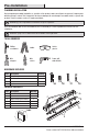
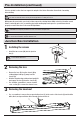
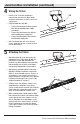
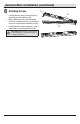
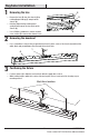
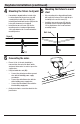
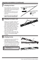
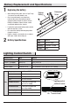
Table Of Contents
- WHAT IS COVERED
- Table of Contents
- Safety Information
- Warranty
- Pre-Installation
- Pre-Installation (continued)
- Junction Box Installation
- Junction Box Installation (continued)
- Keyhole Installation
- Keyhole Installation (continued)
- Keyhole Installation (continued)
- Battery Replacement and Specifications
- Lighting Control Switch
- Test Switch
- Care and Cleaning
- Troubleshooting

10
Battery Replacement and Specications
1
Replacing the battery
□ After turning off the power, refer to Page 7 Step
1 to remove lens and channel cover.
□ Once lens and channel cover have been
removed, disconnect the battery from the
emergency driver via quick connect. Using a
Phillips screwdriver, remove the two screws
securing the battery to the chassis.
□ Position the replacement battery and re-attach
with the same two screws.
□ Re-connect the battery and emergency driver
via quick connects.
□ Replace channel cover and lens in accordance
with steps 8 and 9 above (Page 9).
Emergency
Driver
Backup
Battery
2
Battery Specifications
Type
LifePo4
Size
130*28*30 mm
Capacity
3000mAh / 19.2WH
Voltage
6.4 V
Lighting Control Switch
Switch Position Mode Function
Position 1, Left Factory Use Not Used
Position 2, Left Middle Battery Test Motion sensor off
Position 3, Right Middle Commercial mode 100% illumination active and then 25% illumination in standby
Position 4, Right Residential mode 100% illumination active and then off in standby
Mode
Frequency
5.8 GHz +/- 75 MHz
Power
<0.3mW
Factory
Hold 5s (manufacturer test mode)
Test
No sensor function
Commercial mode
5 min 100% full bright and
then25% in standby
Residential mode
5 min 100% full bright and
thenoff in standby
Mounting Height
Max 4.5 M (vertical)
Movement Detected
0.5~1M/S
Lighting control
switch of sensor
Residential mode
Commercial mode
Test
Factory
FACTORY / TEST / COMM / RES