
Use and Care Guide
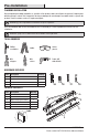
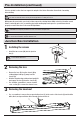
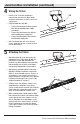
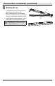
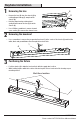
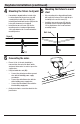
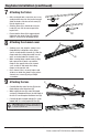
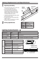
Table Of Contents
- WHAT IS COVERED
- Table of Contents
- Safety Information
- Warranty
- Pre-Installation
- Pre-Installation (continued)
- Junction Box Installation
- Junction Box Installation (continued)
- Keyhole Installation
- Keyhole Installation (continued)
- Keyhole Installation (continued)
- Battery Replacement and Specifications
- Lighting Control Switch
- Test Switch
- Care and Cleaning
- Troubleshooting

4
Pre-Installation (continued)
Select a suitable location that can support the weight of the xture. Determine the method of mounting
before drilling.
WARNING: RISK OF ELECTRIC SHOCK. Ensure the electricity to the wires you are working on is shut off. Either remove the fuse or
turn off the circuit breaker before removing the existing light xture or installing the new one.
With power disconnected to your electrical box, remove the existing xture. Make a sketch of how the current
xture is wired (by wire color) or mark the wires with masking tape and a pencil so you will know how to
properly reconnect the wires to the new LED light xture.
CAUTION: Before beginning installation turn off the circuit breaker and light switch.
IMPORTANT: Depending on the type and orientation of junction box it may be necessary to use the keyhole installation method on page 7
to achieve the desired xture orientation within the room.
Junction Box Installation
1
Installing the screws
□ Install the two screws (AA) into the junction
box (1).
NOTE: Leave 3/8 in. of screw thread exposed to
accommodate the xture base.
1
AA
2
Removing the lens
□ Remove the lens (B) from the chassis (A) by
rotating hinged endcap (C) away from the
chassis (A).
□ Hold the hinged endcap outboard and gently lift
and remove the lens (B) from the chassis (A).
□ Use a Phillips screwdriver to remove channel
cover screws (E) to remove the channel cover.
B
E
D
C
A
3
Removing the knockout
□ Use a screwdriver to remove the pre-punched knockout (1) at the center of the chassis (A) and feed the
white, black, and ground xture wires through the knockout hole.
A
1