
Use and Care Guide
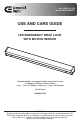
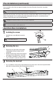
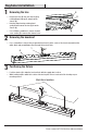
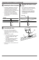
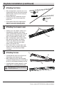
Table Of Contents
- WHAT IS COVERED
- Table of Contents
- Safety Information
- Warranty
- Pre-Installation
- Pre-Installation (continued)
- Junction Box Installation
- Junction Box Installation (continued)
- Keyhole Installation
- Keyhole Installation (continued)
- Keyhole Installation (continued)
- Battery Replacement and Specifications
- Lighting Control Switch
- Test Switch
- Care and Cleaning
- Troubleshooting

5 HOMEDEPOT.com
Please contact 1-877-527-0313 for further assistance.
Junction Box Installation (continued)
4
Wiring the fixture
□ Ensure 3/8 in. of the wire sheathing is
removed from the end of the black, white,
and green xture wires in order to expose the
copper wires.
□ Using included wire nuts (BB):
□ Connect the yellow/green xture ground
wire with the building power supply
ground wire.
□ Connect the white xture wire with the
white building power supply wire.
□ Connect the black xture wires with the
black building supply wire.
□ After ensuring all wire nut connections are
secure, gently tuck all wire connections back
into the junction box.
A
BB
5
Attaching the fixture
□ Attach the xture (A) to the junction box by
aligning the holes on the xture (A) with the
junction box screws (AA) installed in the
previous step. After aligning screw heads (AA)
with mounting slots on xture, rotate xture
until properly aligned with room orientation.
□ After properly oriented, tighten screw heads
(AA) with a Phillips screwdriver, ensuring the
xture is secure and will not move. Then use a
screwdriver to cover channel cover. If proper
xture orientation is not possible due to junction
box/hole positioning, proceed to step 3 of the
“Keyhole Installation” on page 7.
□ Starting on one side, align the channel cover
ange with the locking tabs on the xture
chassis as indicated in schematic (A1). Slide the
ange under the locking tabs and be sure all
wires are tucked under the channel cover.
□ While ensuring ange remains under locking
tabs, squeeze the channel cover until the ange
on the opposite side of the channel cover are
able to slide under the locking anges on the
opposite side. Once channel cover is securely
in place and all wires are inside the channel
cover, replace channel cover screws (E) using a
Phillips screwdriver.
A
E
A1