
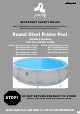
Operation Manual

98
RF-14-GB(V2)
RF-14-GB(V2)
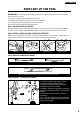
PART4-SET UP THE POOL
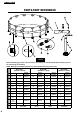
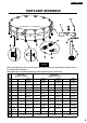
Step1. ACCOUNT FOR ALL PARTS.
Remove all the parts from the carton(s) and place them on the ground in the location where they are to be assembled
Check each part according to “PART REFERENCE” .Make sure all the pieces to be assembled are accounted for.
IMPORTANT: Do not start assembly if any pieces are missing. For replacement pieces call the Consumer Service
telephone number in your area.
The number of persons required for installation: 2 adult at least.
Total installation time except the time for site preparation and water lling :
30 minutes for size Ф10’×30”/Ф12’×30”/Ф12’×32”/Ф12’×39”/Ф12’×48”
60 minutes for size Ф15’×36”/Ф15’×42”/Ф15’×48”/Ф18’×48”
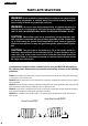
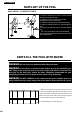
Step2. INSTALL DRAIN VALVES COVER AND STOPPER
Make sure that outer drain plug is inserted into the outer drain cap and drain valve cover is screwed on tightly.Plug the con-
nection holes with the stoppers. (The out drain plug changes according to different size of pool.)
STOPPER Out Drain Plug A Out Drain Plug BDrain Vavle Cover
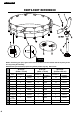
Step3. INSTALL HORIZONTAL BEAM
BEAM A
BEAM A
For all kinds of pool , the combination is A-A.
Slide combined beams into sleeve,the hole on the beams should face outwards.
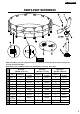
Step4. INSTALL T-JOINT(FOR TYPE A)
3
4
2
5
1
4
1. Use the connection end of the T-Joint to
connect the adjacent horizontal tubes.
2. Insert the Pin into the hole of connected
horizontal tube and T-Joint rmly.
3. Install the vertical leg cap onto the vertical leg.
4. Insert the vertical leg into the T-Joint through
the belt.
5. Insert the pin into the hole of T-Joint and
Vertical Leg.
TIP: If you can’t nd the hole on the horizontal
tube or vertical leg please rotate the tubes until
the pin meets the hole.
BELT