owner’s manual 400W 2/3/4 Channel Amplifier Thank you for purchasing a JL Audio amplifier for your automotive sound system. Your amplifier has been designed and manufactured to exacting standards in order to ensure years of musical enjoyment in your vehicle. For maximum performance, we highly recommend that you have your new amplifier installed by an authorized JL Audio dealer. Your authorized dealer has the training, expertise and installation equipment to ensure optimum performance from this product.
Protect Your Hearing! We value you as a long-term customer. For that reason, we urge you to practice restraint in the operation of this product so as not to damage your hearing and that of others in your vehicle. Studies have shown that continuous exposure to high sound pressure levels can lead to permanent (irreparable) hearing loss. This and all other high-power amplifiers are capable of producing such high sound pressure levels when connected to a speaker system.
Planning Your Installation It is important that you take the time to read this manual and that you plan out your installation carefully. The following are some considerations that you must take into account when planning your installation. Safety Considerations: Your amplifier needs to be installed in a dry, well-ventilated environment and in a manner which does not interfere with your vehicle’s safety equipment (air bags, seat belt systems, ABS brake systems, etc.).
Product Description The JL Audio XD400/4 is a four-channel, full-range audio amplifier utilizing JL Audio NexD™ ultra-high speed switching technology to deliver outstanding fidelity and efficiency. The XD400/4 can be operated with a wide variety of source units and system configurations. Typical Installation Sequence The following represents the sequence for a typical amplifier installation, using an aftermarket source unit or OEM Interface processor (like the CleanSweep CL441dsp).
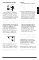
Power Connections Before installing the amplifier, disconnect the negative (ground) wire from the vehicle’s battery. This will prevent accidental damage to the system, the vehicle and your body during installation. Note: Smaller AWG numbers mean bigger wire and vice-versa (1/0 AWG is the largest, 2 AWG is smaller, then 4 AWG, then 8 AWG, etc.). To connect the power wires to the amplifier, first back out the set screw on the top of the terminal block, using the supplied 2.5 mm hex wrench.
Turn-On Lead The XD400/4 uses a conventional +12V remote turn-on lead, typically controlled by the source unit's remote turn-on output. The amplifier will turn on when +12V is present at its “Remote” input and turn off when +12V is switched off. If a source unit does not have a dedicated remote turn-on output, the amplifier’s turn-on lead can be connected to +12V via a switch that derives power from an ignition-switched circuit.
ENGLISH Input Sensitivity Controls The controls labeled “Input Sens.” located in each channel section can be used to match the source unit’s output voltage to the input stage of each pair of amplifier channels for maximum clean output. Rotating the control clockwise will result in higher sensitivity (louder for a given input voltage). Rotating the control counterclockwise will result in lower sensitivity (quieter for a given input voltage.
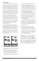
Filter Controls Most speakers are not designed to reproduce the full range of frequencies audible by the human ear. For this reason, most speaker systems are comprised of multiple speakers, each dedicated to reproducing a specific frequency range. Filters are used to select which frequency range is sent to each section of a speaker system.
Remote Level control (Optional) “ Remote Level Mode” Switch: This switch allows you to assign the operation of the HD-RLC to one, or both pairs of channels. In the “All” position, the HD-RLC knob will affect all three channel pairs equally. In the “3&4” position, only the level of channels 3 and 4 will be affected by the HD-RLC knob (Channels 1 & 2 will not). 1) “1&2”: The preamp output delivers the same signal that is connected to the CH 1&2 Inputs.
Speaker OUTPUTS The XD400/4’s speaker outputs are designed to accept 16 AWG - 8 AWG wire. To connect the speaker wires to the amplifier, first back out the set screws on the top of the terminal block, using the supplied 2.5 mm hex wrench. Strip 1/2 inch (12 mm) of insulation from the end of each wire and insert the bare wire into the terminal block, seating it firmly so that no bare wire is exposed.
Status LED / Protection Circuitry There is a single multi-color LED on the top surface of the amplifier to indicate the amplifier’s operating status. For more information on troubleshooting this amplifier, refer to Appendix D (pages 16, 17). 1) Flashing Green: amplifier is powering up, audio output is muted. 2) Constant Green: amplifier is on and functioning normally, audio output is active.
SYSTEM CONFIGURATIONS The XD400/4 is a flexible amplifier, wellsuited for a multitude of system configurations. In this section, the most likely configurations for a system with a single XD400/4 are explained in detail. Once you have selected your desired configuration, you can use the amplifier panel drawing on pages 18 & 19 to mark the required switch positions for easy reference.
14), you can fine tune filter frequencies and attenuate either pair of channels to achieve proper balance. For precise filter frequency information refer to Appendix B (page 15). Bi-Amplified System with one XD400/4 in four-channel mode and a separate subwoofer amplifier This configuration requires that the separate subwoofer amplifier has a built-in low-pass filter. (All JL Audio amplifiers have this feature.
Appendix A: Input Sensitivity Level Setting Following the directions below will allow the installer to adjust the input sensitivity of each amplifier channel pair simply and easily in just a few minutes using equipment which is commonly available in installation bays. Necessary Equipment • Digital AC Voltmeter • CD with a sine-wave test tone recorded at 0 dB reference level in the frequency range to be amplified for that set of channels (50 Hz for subwoofer channels, 1 kHz for a midrange application).
Appendix B: Precise Frequency Selection Chart “Filter FREQ” General Specifications: Recommended Fuse Value: 40A Recommended Fuse Type: MAXI® or AGU ENGLISH Detent Panel Actual Number Marking Freq. Full counter-clockwise: 49 01 . . . . . . . . . . . . . . . . . . . . . . . . . . . . 49 02 . . . . . . . . . . . . “50” . . . . . . . . . . . 49 03 . . . . . . . . . . . . . . . . . . . . . . . . . . . . 50 04 . . . . . . . . . . . . . . . . . . . . . . . . . . . . 50 05 . . . . . . . . . . . . . . . . .
Appendix D: TROUBLESHOOTING “How do I properly set the input sensitivity on my amplifier?” Please r efer to Appendix A (page 14) to set the input sensitivity for maximum, low-distortion output. “My amplifier doesn’t turn on.” Check t he fuse, not just visually, but with a continuity meter. It is possible for a fuse to have poor internal connections that cannot be found by visual inspection. It is best to take the fuse out of the holder for testing.
“My amplifier turns on, but there is no output.” Check t he input signal using an AC voltmeter to measure the voltage from the source unit while an appropriate test tone is played through the source unit (disconnect the input cables from the amplifier prior to this test). The frequency used should be in the range that is to be amplified by the amplifier (example: 50 Hz for a sub bass application or 1 kHz for a full range / high-pass application). A steady, sufficient voltage (between 0.1 and 4.
INSTALLATION NOTES: Use this diagram to document your amplifier’s switch and control positions.
ENGLISH 19
Limited Warranty - Amplifiers (USA) JL AUDIO warrants this product to be free of defects in materials and workmanship for a period of two (2) years. The warranty is extended to three (3) years total if installation is performed by an authorized JL Audio dealer using a JL Audio Premium Power Connection System for power wiring. This warranty is not transferrable and applies only to the original purchaser from an authorized JL AUDIO dealer.
BENUTZERHANDBUCH 400W 2/3/4 Channel Amplifier DEUTSCH Vielen Dank für den Kauf eines JL Audio Verstärkers. Ein optimaler Einbau und korrekter Anschluss garantiert Ihnen eine hervorragende Wiedergabequalität und einwandfreie Funktion über viele Jahre hinweg. Um dies und die Garantiebedingungen zu erfüllen, empfehlen wir Ihnen, die Installation nur von einem autorisierten JL Audio Fachhändler durchführen zu lassen.
SCHÜTZEN SIE IHR GEHÖR! Wir schätzen Sie als unseren Kunden und bitten Sie um eine vernünftige, zurückhaltende Benutzung des Gerätes, um Ihr Hörvermögen und das Ihrer Passagiere nicht zu gefährden. Studien haben bewiesen, dass eine dauerhafte Einwirkung von hohen Schalldruckpegeln zu einem Gehörverlust führen könnte. Dieser und alle anderen leistungsfähigen Verstärker entwickeln einen enorm hohen Schalldruckpegel wenn diese an ein Lautsprecher-System angeschlossen werden.
PLANUNG DER INSTALLATION Es ist wichtig, dass Sie sich die Zeit nehmen, um dieses Benutzerhandbuch ausführlich zu lesen und den Einbau des Verstärkers sorgfältig planen. Die folgenden Punkte sollten bei der Planung der Installation beachtet werden. Von einer Kopf-über-Montage raten wir ab. Falls Sie den Verstärker unter einem Sitz verbauen möchten, stellen Sie sicher, dass ein Freiraum von mindestens 2,5 cm über dem Kühlkörper vorhanden ist, um eine ausreichende Kühlung zu gewährleisten.
ProduKtBESCHREIBUNG Der JL Audio XD400/4 ist ein 4-KanalVollbereichs-Verstärker mit JL Audio NexD™ Ultra-High-Speed-Schaltungstechnologie, welche eine herausragende Tonwiedergabe und Effizienz garantiert. Der XD400/4 Verstärker kann mit vielen System-Konfigurationen betrieben werden.
Lautstärke gleich voll aufzudrehen, bis Sie alle Einstellungen überprüft haben. 15) Stellen Sie dann die Eingangsempfindlichkeit so ein, dass eine ausgewogene Klangbalance zwischen dem Subwoofer und den Lautsprechern erreicht wird. Beachten Sie dazu Anhang A (Seite 14) für die korrekte Anpassung der Eingangsempfindlichkeit. Die Stromanschlüsse des XD400/4 sind für Kabelquerschnitte von 10 mm2 bis 20 mm2 ausgelegt. Der Kabelquerschnitt von 16 mm2 sollte allerdings nicht unterschritten werden.
EINSCHALTLEITUNG Der XD400/4 benötigt eine herkömmliche 12V-Einschaltleitung, welche üblicherweise vom Steuergerät gesteuert wird. Der Verstärker wird dann eingeschaltet, sobald +12V am “Remote”Anschluss anliegen und wieder abgeschaltet wenn das Steuergerät ausgeschaltet wird. Falls Ihr Steuergerät nicht über eine Einschaltleitung verfügt, kann eine andere 12V-Leitung benutzt werden, die mit der Zündung des Fahrzeugs aktiv geschaltet wird.
Sollte jedoch der Eingangspegel der Lautsprecher dennoch zu hoch für den Verstärker sein und Verzerrungen zu hören sein, sollte ein „SignalKonverter“ verwendet werden. DEUTSCH EINGANGSEMPFINDLICHKEIT Die Drehregler mit der Bezeichnung “Input Sens.” befinden sich in der jeweiligen Kanalsektion. Mit diesem Regler können Sie für jedes Kanalpaar getrennt die Eingangsempfindlichkeit mit dem Steuergerät abstimmen, um ein maximales unverzerrtes Ausgangssignal zu erhalten.
FILTEREINSTELLUNGEN Die meisten Lautsprecher sind nicht darauf ausgelegt, das gesamte hörbare Frequenzspektrum des menschlichen Gehörs wiederzugeben. Aus diesem Grund beinhalten die meisten AudioSysteme mehrere Lautsprecherkomponenten, die jeweils ein spezifisches Frequenzband wiedergeben. Die Filter bestimmen für diesen Fall, welche Frequenzen der jeweiligen Lautsprecher-Sektion zugeordnet werden.
PEGELFERNBEDIENUNG (Optional) “Remote Level Mode” Schalter: Je nach Anwendung, kann die HD-RLC nur ein Kanalpaar oder auch beide Kanalpaare regeln. Mit dem Schalter “Remote Level Control” kann dies eingestellt werden. Bei Schalterstellung “All Ch.” werden alle Kanalpaare geregelt, unter “3&4” nur das Kanalpaar 3 & 4 (Kanalpaar 1 & 2 nicht). Verbinden Sie das beigelegte Verbindungskabel der HD-RLC mit dem Anschluss “Remote Level Control” auf dem Anschlusspanel des XD400/4.
Falls Sie in der Konfiguration “Sum” einen Signalverlust im Vergleich zur Konfiguration “1&2” bemerken, liegt eine Signalverzögerung an, entweder auf den Front- oder auf den Rearkanälen. Falls eine Signalverzögerung auf den Front- oder Rearkanälen jedoch erwünscht ist, sollte die Position “1&2” gewählt werden. Hinweis: Bei beiden Konfigurationen wird das Vorverstärker-Ausgangssignal nicht von denen im Verstärker integrierten Filtern verändert, d.h.
1) Nur das linke ODER das rechte Kanalsignal: Falls Sie wünschen, dass nur jeweils das linke oder rechte Kanalsignal im gebrückten Monomodus ausgegeben wird, sollten Sie einen “Y-Adapter” verwenden, der das jeweils gewünschte Audiosignal splittet. Dies ist nützlich, wenn Sie zwei XD400/4 für jeweils ein rechtes und linkes Lautsprechersystem benutzen möchten.
SYSTEM-KONFIGURATIONEN Der XD400/4 ist ein flexibler Verstärker, der multiple System-Konfigurationen ermöglicht. Im folgenden Abschnitt werden die gebräuchlichsten Konfigurationen detalliert beschrieben. Solbald Sie sich für eine Konfiguration entschieden haben, können Sie auf Seite 18 & 19 Ihre Schalter- und Reglerstellungen in der dort abgebildeten Zeichnung markieren.
„Input Sens.“ von Kanal 1/2 & 3/4 (Anhang A, Seite 14) kann mit den Reglern „Filter Freq.“ eine für die angeschlossenen Lautsprecher optimale Feinjustage gewählt werden. Für die präzise Filtereinstellung beachten Sie bitte Anhang B (Seite 15). Zweiwege-Aktiv-System mit einem XD400/4 und einem weiteren Subwoofer-Verstärker Diese Konfiguration benötigt einen separaten Subwoofer-Verstärker mit integriertem Tiefpassfilter.
ANHANG A: Einstellung der Eingangsempfindlichkeit Die folgenden Hinweise helfen dem Anwender die Eingangsempfindlichkeit des/der Verstärker(s) einfach und optimal in ein paar Minuten mithilfe von herkömmlichen Hilfsmitteln einzustellen.
ANHANG B: Tabelle zur präzisen Frequenzeinstellung “Filter FREQ” Allgemeine Angaben: Empfohlener Sicherungswert: 40A Empfohlener Sicherungstyp: AGU oder MaxiFuse™ Anzahl der Signal-Eingänge: differential-symmetrisch, 2 x 2 Cinch-Buchsen Verstärker-Sektion: Verstärker-Topologie: NexD™ Ultra-High Speed Class D Netzteil: Ungerelte MOSFET-Schaltung DEUTSCH RasterReglerAktuelle nummer Markierung Freq. Regler ganz links: 47 01 . . . . . . . . . . . . . . . . . . . . . . . . . . . . 49 02 . . . . . . . . . .
ANHANG D: FEHLERBEHEBUNG “Wie stelle ich die Eingangsempfindlichkeit meines Verstärkers richtig ein?” Bitte beachten Sie dazu Anhang A (Seite 14) um die Eingangsempfindlichkeit optimal einzustellen. “Mein Verstärker schaltet sich nicht ein” Überprüfen Sie die Sicherung mit einem Multimeter. Dies ist erforderlich, da unter Umständen die Sicherung im Innern beschädigt sein könnte und dies nicht durch eine reine visuelle Überprüfung entdeckt werden kann.
“Das Audiosignal schwankt während der Fahrt oder wenn man auf den Verstärker klopft” Überprüfen Sie alle Anschlüsse des Verstärkers und achten Sie auf eine feste Verbindung bei jedem der Anschlüsse und auf ausreichend abisolierte Kontaktfläche an den Kabeln im Innern der Anschlüsse. Überprüfen Sie die Verbindungen zum Verstärkereingang und achten Sie darauf, dass alle Kabel und Stecker der Audioverkabelung fest sitzen.
INSTALLATIONSNOTZIZEN: Benutzen Sie dieses Diagramm um die Schalterstellungen und Reglereinstellungen zu vermerken.
DEUTSCH JL Audio Vertrieb für Deutschland: Audio Design GmbH Am Breilingsweg 3, D-76709 Kronau Tel. +49(0)7253-9465-0, Fax +49(0)7253-9465-10 www.audiodesign.de/jlaudio JL Audio, Inc 10369 North Commerce Pkwy. Miramar, FL 33025, USA www.jlaudio.
www.jlaudio.