
Operator Manual Manual


SECTION 3 - USER RESPONSIBILITIES AND MACHINE CONTROL
3121104 – JLG Lift – 3-5
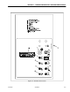
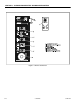
15. Transmission Pump Oil Filter Indicator (Optional)
When illuminated indicates that charge pump filter is
too restrictive and needs to be replaced. This indica-
tor has an integral temperature sensor (70 degrees
F.) so that false signals are not generated when the
hydraulic oil is below normal operating temperature.
16. Engine Coolant Temperature Indicator (Ford)
When illuminated indicates that engine coolant tem-
perature is abnormally high and service is required.
17. Hydraulic Oil Filter Indicator (Optional)
When illuminated indicates that the return oil filter is
too restrictive and needs to be replaced.
18. Engine Oil Temperature Indicator (Deutz Optional)
When illuminated indicates that the temperature of
the engine oil, which also serves as engine coolant,
is abnormally high and service is required.
19. Low Fuel Level Indicator (Optional)
When illuminated indicates that the fuel level is 1/8
full or less. When the light first turns on, there are
approximately four usable gallons of fuel remaining.
20. System Distress Indicator
When illuminated indicates an abnormal condition
with the engine or engine computer.
21. Axles Set Indicator
When illuminated indicates that the axles are fully
extended.
22. Glow Plug Indicator (Deutz)
When illuminated indicates that the Glow Plugs are
operating. After turning on ignition, wait until light
goes out before cranking engine.
23. Capacity Indicator
Illuminates to indicate the maximum platform capac-
ity for the current position of the platform.
24. Exceeding Operating Radius Indicator
Illuminates to indicate that the platform has
exceeded the approved operating radius and the
boom must be retracted to bring the platform back
into the proper radius.
25. Broken Fan Belt Indicator
Illuminates to indicate that the engine fan belt has
broken. When illuminated, the engine must be shut
down immediately to prevent damage.
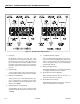
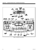
Remote Control Box (120SXJ Only)
NOTE: To operate the remote control box, set the SELECT
SWITCH to GROUND and start the engine.
1. Power/Emergency Stop Switch
Position the Power/Emergency Stop switch to the on
position to activate the controls on the remote con-
trol box.
2. Front Steer /Jack / Axle Switch
This switch allows the operator to steer the front or
four wheel steering as desired, extend or retract the
jacks, or extend or retract the axles depending upon
the position of the Jack/Steer/Axle Select Switch.
The Speed Control switch does not affect the steer
function.
3. Drive Switch
Position the Drive switch to forward or reverse as
desired.
4. Speed Control
Rotate the speed control when driving to increase or
decrease drive speed as desired.
5. Steer Select Switch
This switch allows the operator to select between
four wheel diagonal steering, front wheel steering, or
four wheel crab steering.
6. Front/Rear Jack Switch
This switch allows the operator to select between
operation of the front or rear jack.
7. Jack/Steer/Axle Select Switch
This switch allows the operator to select the Jack,
Steer, or Axle function.