
Parts Manual User Manual

3121106 1-13
S
E
C
T
I
O
N
1
F
R
A
M
E
SECTION 1 FRAME
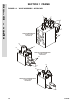
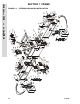
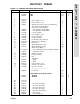
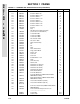
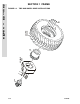
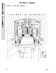
FIGURE 1-4. TIRE AND WHEEL DRIVE INSTALLATIONS
FIG & ITEM # PART NUMBER DESCRIPTION QTY. REV.
TIRE AND WHEEL DRIVE INSTALLATIONS Ref.
0259895 WHEEL DRIVE INSTALLATION Ref. B
1Not Used
2Not Used
3 0701617 Bolt (Metric)16mm x 45mm (12 Per Wheel) 48
4 4892000 Washer Hardened 5/8” (12 Per Wheel) 48
— — — — — — — — — —
0100019 Loctite #271 A/R
0259878 HUB AND MOTOR ASSEMBLY Ref. C
101 2780248 Drive Hub Assembly (See Figure 1-5 for Breakdown) 4
102 3160248
Drive Motor Assembly
(See Figure 1-6 for Breakdown)
4
TIRE AND WHEEL INSTALLATIONS (FOAM-FILLED) Ref.
0259909 100SX/110SX & 110SXJ Ref. A
0259906 120SXJ Ref. A
201 Tire and Wheel Assembly (Foam-Filled) Options: 2
0259907 Right Side (100SX/110SX & 110SXJ)
0259904 Right Side (120SXJ)
202 Tire and Wheel Assembly (Foam-Filled) Options: 2
0259908 Left Side (100SX/110SX & 110SXJ)
0259905 Left Side (120SXJ)
4520215 Tire 385/65 x 22.5
4640113 Valve
Note: Assemblies may require ballast/foam fill-
ing to manufacturer’s specifications prior to
installing on a machine. Refer to Operation &
Safety or Service & Maintenance Manuals. Pur-
chase individual tire and/or rim only if able to
foam fill tire & wheel assembly, otherwise, pur-
chase complete assembly.
203 0701619 Bolt (Metric)16mm x 55mm (16 Per Wheel) 64
204 4892000 Washer Hardened 5/8” (16 Per Wheel) 64