
Service Manual


SECTION 6 - TROUBLESHOOTING
6-32 – JLG Lift – 3121231
Code 33 - Both PHP Bars - UP
Code 34 - P2-Auxiliary #1 - Inhibit
Check For These Obvious Conditions First:
• Platform Gates Closed.
• Pressure on the Platform Foot-switch (after power up).
NOTE: In the procedures below, if you check continuity between pin 6 and 16 it should show open circuit, when the platform
gates are closed and nothing is on the foot switch. When you step on the foot switch with the gates closed, you should
see a closed circuit.
Code 35 - P2-Auxiliary #1 - Tie Down
Check For These Obvious Conditions First:
• Pressure on the Platform Foot-switch during machine power up.
NOTE: In the procedures below, if you check continuity between pin 6 and 16 it should show open circuit, when the platform
gates are closed and nothing is on the foot-switch. When you step on the foot switch with the gates closed, you should
see a closed circuit.
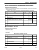
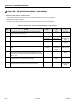
Table 6-35. Code 33 - Both PHP Bars - UP
STEP ACTION SPEC YES NO
1. Perform steps in Code 2, Left PHP Bar UP then, Code 3, Right PHP Bar UP.
Do either of these steps correct the problem?
—DoneGo to Step 2
2. Perform steps in Table 6-5 - Machine In Drive Speed Cut-Back (Turtle)
Mode All The Time, of this section.
— Done Consult Factory
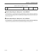
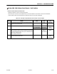
Table 6-36. Code 34 - P2-Auxiliary #1 - Inhibit
STEP ACTION SPEC YES NO
1. At the Ground Control Module, P2 connector, check the voltage across
pins-16 (orange/red 49-5) and 6 (black 12) is reading within specification?
0 - 2V DC Go to Step 2 Replace Ground
Control Module
2. Remove the P2 connector from the Ground Station Module; check continu-
ity of the individual wires in the platform harness. (P2 to platform junction
box),
— Go to Step 3 Repair or
Replace Platform
Harness
3. Check continuity of gate switches and foot-switch circuit. (Switches are
wired in series; doors shut and foot switch depressed, circuit will be
closed)
Consult Factory Replace Compo-
nent or Repair
Wires
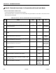
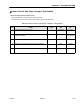
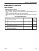
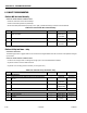
Table 6-37. Code 35 - P2-Auxiliary #1 - Tie Down
STEP ACTION SPEC YES NO
1. At the Ground Control Module, P2 connector, check the voltage across
pins-16 (orange/red 49-5) and 6 (black 12) is reading within specification?
0 - 2V DC Go to Step 2 Replace Ground
Control Module
2. Remove the P2 connector from the Ground Station Module; check continu-
ity of the individual wires in the platform harness. (P2 to platform junction
box),
— Go to Step 3 Repair or
Replace Platform
Harness