
Service Manual


SECTION 3 - BASE COMPONENTS
3-2 – JLG Lift – 3121231
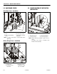
3.2 BASE FRAME COVERS
Drive Motor Cover - Installation
Battery Charger Cover - Installation
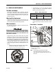
3.3 DRIVE/ELEVATION CUT-OUT SWITCH
INSTALLATION
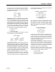
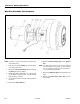
Drive Motor Cover Installation
1. Cover
2. Attach Screws and Wash-
ers (a)
3. Set Cover Tab on Lower
portion of Cover, in Slot on
Base Frame
NOTE: (a) Apply Loctite #242 to screw threads before
tightening.
Batttery Charger Cover Installation
1. Charger Cover
2. Front Attach Screws
and Washers
3. Rear Attach Screws
and Washers - Loosen
Only - Cover Slotted
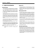
Drive/Elevation Switch Cut-Out Switch Installation
1. Mounting Screws (a)
2. Proximity Switch (b)
3. Switch Mounting Block
4. Frame Mounting Holes
NOTE: Elevate and block platform to gain access to
switch.
(a) Apply Loctite #242 to mounting screw
threads on final assembly.