
Service Manual

SECTION 4 - CONTROL COMPONENTS
3121231 – JLG Lift – 4-11
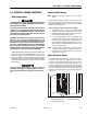
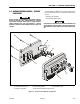
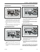
Power Selector/EStop Switch Installation
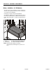
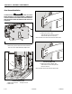
Emergency Stop Switch Installation
1. Emergency Stop Button 4. Nut
2. Button Seal 5. Emergency Stop Switch
3. Square Lock Washer 6. Switch Lock/Release Lever
Note: Tighten nut enough to keep button from turning.
Reattach wires to same terminals on new switch.
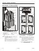
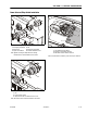
Power Selector Switch Installation
1. Nut
2. Power Selector Switch
3. Align and insert tab on switch into slot on cover.
Note: Re-attach wires to the same terminals on new switch.
1
2
4
5
6
1
2
3
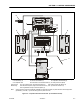
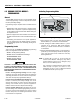
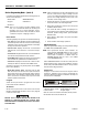
Power Selector/EStop Switch - Connectors Location
1. LCD and Button Circuit Board
2. Emergency Stop Switch Connector
3. Main Power Selector Switch Connector
Note: To release switch connectors, push tab on top of connector.
2
3
1