Operation and Safety Manual Original Instructions - Keep this manual with the machine at all times.
FOREWORD FOREWORD This manual is a very important tool! Keep it with the machine at all times. The purpose of this manual is to provide owners, users, operators, lessors, and lessees with the precautions and operating procedures essential for the safe and proper machine operation for its intended purpose. Due to continuous product improvements, JLG Industries, Inc. reserves the right to make specification changes without prior notification. Contact JLG Industries, Inc. for updated information.
FOREWORD SAFETY ALERT SYMBOLS AND SAFETY SIGNAL WORDS This is the Safety Alert Symbol. It is used to alert you to the potential personal injury hazards. Obey all safety messages that follow this symbol to avoid possible injury or death INDICATES AN IMMINENTLY HAZARDOUS SITUATION. IF NOT AVOIDED, WILL RESULT IN SERIOUS INJURY OR DEATH. THIS DECAL WILL HAVE A RED BACKGROUND. INDICA TES A POTENTIALLY HAZARDOUS SITUATIO N. IF NOT AVOIDED, COULD RESULT IN SERIOUS INJURY OR DEATH.
FOREWORD For: THIS PRODUCT MUST COMPLY WITH ALL SAFETY RELATED BULLETINS. CONTACT JLG INDUSTRIES, INC. OR THE LOCAL AUTHORIZED JLG REPRESENTATIVE FOR INFORMATION REGARDING SAFETYRELATED BULLETINS WHICH MAY HAVE BEEN ISSUED FOR THIS PRODUCT. • Accident Reporting • Product Safety Publications • Current Owner Updates • Questions Regarding Product Safety JLG INDUSTRIES, INC. SENDS SAFETY RELATED BULLETINS TO THE OWNER OF RECORD OF THIS MACHINE. CONTACT JLG INDUSTRIES, INC.
FOREWORD REVISION LOG Original Issue d - December 17, 2012 – JLG Lift – 3121286
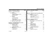
TABLE OF CONTENTS SECTION - PARAGRAPH, SUBJECT PAGE SECTION - PARAGRAPH, SUBJECT SECTION - 1 - SAFETY PRECAUTIONS 1.1 1.2 1.3 1.4 1.5 General . . . . . . . . . . . . . . . . . . . . . . . . . . . . . . . . 2-8 GENERAL . . . . . . . . . . . . . . . . . . . . . . . . . . . . . . . . .1-1 PRE-OPERATION . . . . . . . . . . . . . . . . . . . . . . . . . . .1-1 Operator Training and Knowledge . . . . . . . . . . . 1-1 Workplace Inspection . . . . . . . . . . . . . . . . . . . . . 1-2 Machine Inspection . .
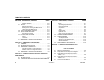
TABLE OF CONTENTS SECTION - PARAGRAPH, SUBJECT PAGE SECTION - PARAGRAPH, SUBJECT Platform Rotation . . . . . . . . . . . . . . . . . . . . . . . 4-10 BOOM . . . . . . . . . . . . . . . . . . . . . . . . . . . . . . . . . . 4-10 Swinging the Boom . . . . . . . . . . . . . . . . . . . . . 4-11 Raising and Lowering the Main Boom . . . . . . 4-11 Telescoping the Main Boom . . . . . . . . . . . . . . 4-11 4.8 FUNCTION SPEED CONTROL . . . . . . . . . . . . . . . 4-12 4.9 SHUT DOWN AND PARK . . . . . . . . . .
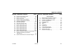
TABLE OF CONTENTS SECTION - PARAGRAPH, SUBJECT 3-2. 3-3. 3-4. 4-1. 4-2. 4-3. 4-4. 4-5. 4-6. 4-7. 4-8. 4-9. 4-10. 4-11. 4-12. 6-1. 6-2. 6-3. 3121286 PAGE SECTION - PARAGRAPH, SUBJECT Ground Control Indicator Panel . . . . . . . . . . . . . . . .3-6 Platform Control Console. . . . . . . . . . . . . . . . . . . . .3-8 Platform Light Panel . . . . . . . . . . . . . . . . . . . . . . . .3-11 Position of Least Forward Stability . . . . . . . . . . . . .4-3 Position of Least Backward Stability . . . . . . . .
TABLE OF CONTENTS SECTION - PARAGRAPH, SUBJECT PAGE SECTION - PARAGRAPH, SUBJECT PAGE This page left blank intentionally.
SECTION 1 - SAFETY PRECAUTIONS SECTION 1. SAFETY PRECAUTIONS 1.1 GENERAL 1.2 This section outlines the necessary precautions for proper and safe machine operation and maintenance. For proper machine use, it is mandatory that a daily routine is established based on the content of this manual. A maintenance program, using the information provided in this manual and the Service and Maintenance Manual, must also be established by a qualified person and followed to ensure the machine is safe to operate.
SECTION 1 - SAFETY PRECAUTIONS • Read, understand, and obey all DANGERS, WARNINGS, CAUTIONS, and operating instructions on the machine and in this manual. • Use the machine in a manner which is within the scope of its intended application set by JLG. • All operating personnel must be familiar with the emergency controls and emergency operation of the machine as specified in this manual.
SECTION 1 - SAFETY PRECAUTIONS 1.3 OPERATION • Supplies or tools which extend outside the platform are prohibited unless approved by JLG. General • When driving, always position boom over rear axle in line with the direction of travel. Remember, if boom is over the front axle, steer and drive functions will be reversed. • Do not use the machine for any purpose other than positioning personnel, their tools, and equipment.
SECTION 1 - SAFETY PRECAUTIONS • Before operating the machine, make sure all gates are closed and fastened in their proper position. • Use extreme caution when entering or leaving platform. Be sure that the boom is fully lowered. It may be necessary to telescope out to position the platform closer to the ground for entry/exit. Face the machine, maintain “three point contact” with the machine, using two hands and one foot or two feet and one hand during entry and exit.
SECTION 1 - SAFETY PRECAUTIONS Table 1-1. Minimum Approach Distances (M.A.D.) Voltage Range (Phase to Phase) 0 to 50 KV 10 (3) Over 50KV to 200 KV 15 (5) Over 200 KV to 350 KV 20 (6) Over 350 KV to 500 KV 25 (8) Over 500 KV to 750 KV 35 (11) Over 750 KV to 1000 KV 45 (14) NOTE: • Maintain distance from electrical lines, apparatus, or any energized (exposed or insulated) parts according to the Minimum Approach Distance (MAD) as shown in Table 11.
SECTION 1 - SAFETY PRECAUTIONS • The minimum approach distance may be reduced if insulating barriers are installed to prevent contact, and the barriers are rated for the voltage of the line being guarded. These barriers shall not be part of (or attached to) the machine. The minimum approach distance shall be reduced to a distance within the designed working dimensions of the insulating barrier.
SECTION 1 - SAFETY PRECAUTIONS • Do not elevate platform or drive with platform elevated while on a sloping, uneven, or soft surface. • If boom assembly or platform is in a position that one or more wheels are off the ground, all persons must be removed before attempting to stabilize the machine. Use cranes, forklift trucks, or other appropriate equipment to stabilize machine. • Before driving on floors, bridges, trucks, and other surfaces, check allowable capacity of the surfaces.
SECTION 1 - SAFETY PRECAUTIONS • Use the boom functions, not the drive function, to position the platform close to obstacles. • Always post a lookout when driving in areas where vision is obstructed. • Keep non-operating personnel at least 6 ft. (1.8m) away from machine during all driving and swing operations. • Limit travel speed according to conditions of ground surface, congestion, visibility, slope, location of personnel, and other factors which may cause collision or injury to personnel.
SECTION 1 - SAFETY PRECAUTIONS 1.5 ADDITIONAL HAZARDS / SAFETY • Do not refuel the machine with the engine running. • Battery fluid is highly corrosive. Avoid contact with skin and clothing at all times. • Do not use machine as a ground for welding. • When performing welding or metal cutting operations, precautions must be taken to protect the chassis from direct exposure to weld and metal cutting spatter. 3121286 – JLG Lift – • Charge batteries only in a well ventilated area.
SECTION 1 - SAFETY PRECAUTIONS DO NOT OPERATE THE MACHINE WHEN WIND CONDITIONS EXCEED 28 MPH (12.5 M/S). Table 1-2. Beaufort Scale (For Reference Only) 1-10 Wind Speed Beaufort Number mph m/s 0 0 0-0.2 Description Land Conditions Calm Calm. Smoke rises vertically 1 1-3 0.3-1.5 Light air Wind motion visible in smoke 2 4-7 1.6-3.3 Light breeze Wind felt on exposed skin. Leaves rustle 3 8-12 3.4-5.4 Gentle breeze Leaves and smaller twigs in constant motion 4 13-18 5.5-7.
SECTION 2 - USER RESPONSIBILITIES, MACHINE PREPARATION, AND INSPECTION SECTION 2. USER RESPONSIBILITIES, MACHINE PREPARATION, AND INSPECTION 2.1 PERSONNEL TRAINING 6. The safest means to operate the machine where overhead obstructions, other moving equipment, and obstacles, depressions, holes, or dropoffs exist. The aerial platform is a personnel handling device; so it is necessary that it be operated and maintained only by trained personnel.
SECTION 2 - USER RESPONSIBILITIES, MACHINE PREPARATION, AND INSPECTION 2.2 PREPARATION, INSPECTION, AND MAINTENANCE The following table covers the periodic machine inspections and maintenance required by JLG Industries, Inc. Consult local regulations for further requirements for aerial work platforms.
SECTION 2 - USER RESPONSIBILITIES, MACHINE PREPARATION, AND INSPECTION Table 2-1.Inspection and Maintenance Table Type Primary Responsibility Frequency Service Qualification Reference Pre-Start Inspection Before using each day; or whenever there’s an Operator change. User or Operator User or Operator Operator and Safety Manual Pre-Delivery Inspection (See Note) Before each sale, lease, or rental delivery.
SECTION 2 - USER RESPONSIBILITIES, MACHINE PREPARATION, AND INSPECTION Pre-Start Inspection The Pre-Start Inspection shall include each of the following: 1. Cleanliness – Check all surfaces for leakage (oil, fuel, or battery fluid) or foreign objects. Report any leakage to the proper maintenance personnel. 2. Structure - Inspect the machine structure for dents, damage, weld or parent metal cracks or other discrepancies. 4.
SECTION 2 - USER RESPONSIBILITIES, MACHINE PREPARATION, AND INSPECTION 2. From the platform control console: 11. Function Check – Once the “Walk-Around” Inspection is complete, perform a functional check of all systems in an area free of overhead and ground level obstructions. Refer to Section 4 for more specific instructions. a. Ensure that the control console is firmly secured in the proper location; b. Check that all guards protecting the switches or locks are in place; c.
SECTION 2 - USER RESPONSIBILITIES, MACHINE PREPARATION, AND INSPECTION 13 1 2 10 3 11 4 5 9 8 6 7 12 1. Base Boom Section 2. Powertrack 3. Lift Cylinder 4. Master Cylinder 5. Ground Control Box 6. Frame 7. Front Drive/Steer Wheels 8. Turntable 9. Rear Drive Wheels 10. Fly Boom Section 11. Platform Level Cylinder 12. Platform 13. Platform Control Console Figure 2-1.
SECTION 2 - USER RESPONSIBILITIES, MACHINE PREPARATION, AND INSPECTION 2 5 6 9 15 7 12 7 11 13 8 17 16 1 10 8 4 2 22 5 5 21 18 23 8 6 7 17 19 20 5 3 8 14 7 Figure 2-2.
SECTION 2 - USER RESPONSIBILITIES, MACHINE PREPARATION, AND INSPECTION General Begin the "Walk-Around Inspection" at Item 1, as noted on the diagram. Continue checking each item in sequence for the conditions listed in the following checklist. TO AVOID POSSIBLE INJURY BE SURE MACHINE POWER IS OFF .
SECTION 2 - USER RESPONSIBILITIES, MACHINE PREPARATION, AND INSPECTION 8. Wheel/Tire Assemblies - Properly secured, no missing lug nuts. Inspect for worn tread, cuts, tears or other discrepancies. Inspect wheels for damage and corrosion. 15. Fuel Tank - See Inspection Note. 9. Tie Rod and Steering Linkage - See Inspection Note. 18. Battery - Proper electrolyte levels if adjustable; cables tight, no visible damage or corrosion. 10. Turntable Lock - Operable. 16.
SECTION 2 - USER RESPONSIBILITIES, MACHINE PREPARATION, AND INSPECTION NOTES: 2-10 – JLG Lift – 3121286
SECTION 3 - MACHINE CONTROLS AND INDICATORS SECTION 3. MACHINE CONTROLS AND INDICATORS 3.1 GENERAL NOTE: THE MANUFACTURER HAS NO DIRECT CONTROL OVER MACHINE APPLICATION AND OPERATION. THE USER AND OPERATOR ARE RESPONSIBLE FOR CONFORMING WITH GOOD SAFETY PRACTICES. This section provides the necessary information needed to understand control functions. 3.2 NOTE: CONTROLS AND INDICATORS All machines are equipped with control panels that use symbols to indicate control functions.
SECTION 3 - MACHINE CONTROLS AND INDICATORS Ground Control Station TO AVOID SERIOUS INJURY, DO NOT OPERATE MACHINE IF ANY CONTROL LEVERS OR TOGGLE SWITCHES CONTROLLING PLATFORM MOVEMENT DO NOT RETURN TO THE OFF POSITION WHEN RELEASED. ONLY USE THE PLATFORM LEVELING OVERRIDE FUNCTION FOR SLIGHT LEVELING OF THE PLATFORM. INCORRECT USE COULD CAUSE THE LOAD/OCCUPANTS TO SHIFT OR FALL. FAILURE TO DO SO COULD RESULT IN DEATH OR SERIOUS INJURY. 2. Platform Leveling Override (See Figure 3-1.
SECTION 3 - MACHINE CONTROLS AND INDICATORS 1 2 10 3 4 1. 2. 3. 4. 5. 6. 7. 8. 9. 10. Indicator Panel Platform Leveling Override Platform Rotate Engine Start/Auxiliary Power Switch/Function Enable Hourmeter Power/Emergency Stop Platform/Ground Select Lift Swing Telescope 5 9 6 7 8 Figure 3-1.
SECTION 3 - MACHINE CONTROLS AND INDICATORS 4. Engine Start/ Auxiliary Power Switch /Function Enable 6. Power/Emergency Stop Switch To start the engine, the switch must be held "Up" until the engine starts. A two-position red mushroom shaped switch supplies power to Platform/Ground Select switch when pulled out (on). When pushed in (off), power is shut off to the Platform/Ground Select switch. To use auxiliary power, the switch must be held “Down” for duration of auxiliary pump use.
SECTION 3 - MACHINE CONTROLS AND INDICATORS 8. Lift Control 2. Low Engine Oil Pressure Indicator Provides raising and lowering of the boom. Indicates that engine oil pressure is below normal and service is required. 3. High Engine Coolant Temperature Indicator 9. Swing Control Indicates that engine coolant temperature is abnormally high and service is required. Provides 355 degrees non-continuous turntable rotation. 4.
SECTION 3 - MACHINE CONTROLS AND INDICATORS 1. Battery Malfunction 4. System Distress 2. Low Engine Oil Pressure 5. Glow Plug 3. High Engine Coolant Temp. Figure 3-2.
SECTION 3 - MACHINE CONTROLS AND INDICATORS Platform Station 2. Platform Leveling Override A three position switch allows the operator to adjust the automatic self leveling system. This switch is used to adjust platform level in situations such as ascending/descending a grade. (See Figure 3-3., Platform Control Console) TO AVOID SERIOUS INJURY, DO NOT OPERATE MACHINE IF ANY CONTROL LEVERS OR TOGGLE SWITCHES CONTROLLING PLATFORM MOVEMENT DO NOT RETURN TO THE OFF OR NEUTRAL POSITION WHEN RELEASED. 3.
SECTION 3 - MACHINE CONTROLS AND INDICATORS 1 3 2 5 4 6 1702676 D 1001107677 A 1702566 B 1702565 B 1702567 B 11 1. 2. 3. 4. 3-8 10 9 8 7 Drive Speed/Torque Select 5. Start/Auxiliary Descent Enable 9. Platform Rotate 10. Function Speed Control Platform Leveling Override 6. Drive Orientation Override 7. Drive/Steer 11. Main Lift/Swing Controller Horn Power/Emergency Stop 8. Telescope Figure 3-3.
SECTION 3 - MACHINE CONTROLS AND INDICATORS 5. Start/Auxiliary Descent Enable NOTE: To operate the Drive joystick, pull up on the locking ring below the handle. NOTE: The Drive joystick is spring loaded and will automatically return to neutral (off) position when released. When pushed forward, the switch energizes the starter motor to start the engine. When pushed back, it energizes Auxiliary Descent Enable which allows the boom to be lowered or swing to be operated in the event of engine malfunction.
SECTION 3 - MACHINE CONTROLS AND INDICATORS Platform Control Indicator Panel 10. Function Speed Control This control affects the speed of telescope and platform rotate. Turning the knob all the way counterclockwise until it clicks puts drive, main lift and swing into creep mode. NOTE: NOTE: (See Figure 3-4., Platform Light Panel) 1. AC Generator (If Equipped) Indicates the generator is in operation. To operate the Main Boom Lift/Swing joystick, pull up on the locking ring below the handle. 2.
SECTION 3 - MACHINE CONTROLS AND INDICATORS 1 2 7 3 4 6 5 1. AC Generator 2. Tilt Alarm Warning 3. Glow Plug/Wait to Start 6. System Distress 4. Footswitch/Enable 7. Drive Orientation 5. Creep Speed Figure 3-4.
SECTION 3 - MACHINE CONTROLS AND INDICATORS 3. Glow Plug/Wait to Start Indicator Indicates the glow plugs are operating. After turning on ignition, wait until light goes out before cranking engine. FOOTSWITCH MUST BE ADJUSTED IF FUNCTIONS ACTIVATE WHEN SWITCH ONLY OPERATES WITHIN LAST 1/4" OF TRAVEL, TOP OR BOTTOM. 4. Footswitch/Enable Indicator 5. Creep Speed Indicator To operate any function, the footswitch must be depressed and the function selected within seven seconds.
SECTION 3 - MACHINE CONTROLS AND INDICATORS 7. Drive Orientation Indicator When the boom is swung beyond the rear drive tires or further in either direction, the Drive Orientation indicator will illuminate when the drive function is selected. This is a signal for the operator to verify that the drive control is being operated in the proper direction (i.e. controls reversed situations).
SECTION 3 - MACHINE CONTROLS AND INDICATORS NOTES: 3-14 – JLG Lift – 3121286
SECTION 4 - MACHINE OPERATION SECTION 4. MACHINE OPERATION 4.1 DESCRIPTION This machine is a self-propelled hydraulic personnel lift equipped with a work platform on the end of an elevating and rotating boom. 3121286 – JLG Lift – The primary operator control station is in the platform. From this control station, the operator can drive and steer the machine in both forward and reverse directions. The operator can raise or lower the boom or swing the boom to the left or right.
SECTION 4 - MACHINE OPERATION 4.2 BOOM OPERATING CHARACTERISTICS AND LIMITATIONS Capacities Raising boom above horizontal with or without any load in platform, is based on the following criteria: 1. Machine is positioned on a smooth, firm and level surface. Stability Machine stability is based on two (2) conditions which are called Forward and Backward stability. The machine’s position of least Forward stability is shown in Figure 4-1.
SECTION 4 - MACHINE OPERATION TURNTABLE ROTATED 90 DEGREES MAIN BOOM FULLY EXTENDED MACHINE WILL "TIP OVER" IN THIS DIRECTION IF OVERLOADED OR OPERATED ON AN OUT-OF-LEVEL SURFACE 10° Figure 4-1.
SECTION 4 - MACHINE OPERATION . PLATFORM ROTATED 90 DEGREES MACHINE WILL "TIP OVER" IN THIS DIRECTION IF OVERLOADED OR OPERATED ON AN OUT-OF-LEVEL SURFACE MAIN BOOM FULLY ELEVATED AND FULLY RETRACTED TURNTABLE ROTATED 90 DEGREES Figure 4-2.
SECTION 4 - MACHINE OPERATION 4.3 ENGINE OPERATION 1. Turn key of Platform/Ground Select switch to Ground. NOTE: Initial starting should always be performed from the Ground Control station. 2. Pull the Power/Emergency Stop switch to On. Starting Procedure 3. Push the Engine Start switch until engine starts. IF ENGINE FAILS TO START PROMPTLY, DO NOT CRANK FOR AN EXTENDED TIME. SHOULD ENGINE FAIL TO START AGAIN, ALLOW STARTER TO “COOL OFF” FOR 2-3 MINUTES.
SECTION 4 - MACHINE OPERATION 6. From Platform, pull Power/Emergency Stop switch out. 2. Push Power/Emergency Stop switch in. 7. Push the Engine Start switch until engine starts. 3. Turn Platform/Ground Select switch to Off. Refer to Engine Manufacturer’s manual for detailed information. NOTE: Footswitch must be in released (up) position before starter will operate. If starter operates with footswitch in the depressed position, DO NOT OPERATE MACHINE.
SECTION 4 - MACHINE OPERATION 4.4 TRAVELING (DRIVING) See Figure 4-3., Grade and Side Slopes NOTE: Refer to the Operating Specifications table for Gradeability and Sideslope ratings. All ratings for Gradeability and Sideslope are based upon the machine’s boom being in the stowed position, fully lowered, and retracted. Traveling is limited by two factors: 1. Gradeability, which is the percent of grade of the incline the machine can climb. 2.
SECTION 4 - MACHINE OPERATION Traveling Forward and Reverse IF WHEEL SLIPPAGE IS EVIDENT WHEN DRIVING ON UNEVEN OR MUDDY TERRAIN, MANUALLY POSITION THE DRIVE SPEED/TORQUE SELECT SWITCH BACK TO THE MAXIMUM TORQUE MODE TO CONTINUE TRAVEL. 1. At Platform Controls, pull out Emergency Stop switch, start engine, and activate footswitch. 2. Position Drive controller to Forward or Reverse as desired. This machine is equipped with a Drive Orientation Indicator.
SECTION 4 - MACHINE OPERATION GRADE SIDE SLOPE LEVEL Figure 4-3.
SECTION 4 - MACHINE OPERATION 4.5 STEERING 4.7 Position thumb switch on Drive/Steer controller to Right for steering right, or to Left for steering left. 4.6 A RED TILT WARNING LIGHT IS LOCATED ON THE CONTROL CONSOLE WHICH LIGHTS WHEN THE CHASSIS IS ON AN EXCESSIVE SLOPE. DO NOT SWING OR RAISE BOOM ABOVE HORIZONTAL WHEN LIGHT IS LIT. PLATFORM ONLY USE THE PLATFORM LEVELING OVERRIDE FUNCTION FOR SLIGHT LEVELING OF THE PLATFORM. INCORRECT USE COULD CAUSE THE LOAD/OCCUPANTS TO SHIFT OR FALL.
SECTION 4 - MACHINE OPERATION Raising and Lowering the Main Boom To raise or lower the Main Boom, position the Main Boom Lift switch to Up or Down until the desired height is reached. TO AVOID SERIOUS INJURY, DO NOT OPERATE MACHINERY IF ANY CONTROL LEVER OR TOGGLE SWITCH CONTROLLING PLATFORM MOVEMENT DOES NOT RETURN TO THE ‘OFF’ OR NEUTRAL POSITION WHEN RELEASED.
SECTION 4 - MACHINE OPERATION 4.8 FUNCTION SPEED CONTROL This control affects the speed of telescope and platform rotate. Turning the knob all the way counterclockwise until it clicks puts drive, main lift and swing into creep mode. 4.9 SHUT DOWN AND PARK Shut Down and Park The procedures to shut down and park the machine are as follows: 1. Drive machine to a reasonably well protected area. 2. Ensure boom is lowered over rear drive axle. 3. Shut down Emergency Stop at Platform Controls. 4.
SECTION 4 - MACHINE OPERATION 4.10 LIFTING AND TIE DOWN Tie Down (See Figure 4-5.) Lifting 1. Refer to the Serial Number Plate, refer to the Specifications section of this manual, or weigh the individual unit to find out the Gross Vehicle Weight. WHEN TRANSPORTING THE MACHINE, THE BOOM MUST BE FULLY LOWERED INTO THE BOOM REST. 1. Place the boom in the stowed position with the turntable locked. 2. Place the boom in the stowed position with the turntable locked. 2.
SECTION 4 - MACHINE OPERATION 4.11 EMERGENCY TOWING PROCEDURES THE ALLOWABLE TOWING SPEED IS 1.9 MPH (3 KPH). THE MAXIMUM ALLOWABLE TOWING DISTANCE IS 0.6 MILES (1 KM). 1. Chock wheels securely. 2. Engage the mechanical release on both drive hubs by loosening, completely reversing, and tightening the two bolts on each hub. Refer to Figure 4-4., Drive Disconnect Hub 3. Connect suitable equipment, remove chocks, and move machine. After moving machine, complete the following procedure: 1.
SECTION 4 - MACHINE OPERATION Figure 4-5.
SECTION 4 - MACHINE OPERATION 17 3 21 22 35 42 4 34 13 42 Figure 4-6.
SECTION 4 - MACHINE OPERATION 16 3 22 42 42 33 4 Figure 4-7.
SECTION 4 - MACHINE OPERATION 12 3 26 12 14 3 3 21 20 21 20 25 LIFTING LUG FOR 80RS/24RS 38 36 21 22 28 41 2 41 11 2 11 Figure 4-8.
SECTION 4 - MACHINE OPERATION 12 3 26 12 14 3 3 21 20 21 20 25 LIFTING LUG FOR 80RS/24RS 38 36 21 22 28 41 2 41 11 2 11 Figure 4-9.
SECTION 4 - MACHINE OPERATION 44 18 23 37 18 27 23 40 19 20 15 26 14 9 29 39 20 39 Figure 4-10.
SECTION 4 - MACHINE OPERATION 5 8 24 6 7 45 Figure 4-11.
SECTION 4 - MACHINE OPERATION 10 10 TOP VIEW OF FRAME Figure 4-12.
SECTION 4 - MACHINE OPERATION Item # 3121286 ANSI Korea Chinese Portuguese Spanish 1001139024-A 1001139026-A 1001139027-A 1001139028-A 1001139029-A French 1001139030- Japan 1001139031- 1 -- -- -- -- -- -- -- 2 1701499 1701499 1701499 1701499 1701499 1701499 1701499 3 1701500 1701500 1701500 1701500 1701500 1701500 1701500 4 1701501 1701501 1701501 1701501 1701501 1701501 1701501 5 1701502 1701502 1701502 1701502 1701502 1701502 1701502 6 1701503 1701503 170150
SECTION 4 - MACHINE OPERATION Item # 4-24 ANSI Korea Chinese Portuguese Spanish 1001139024-A 1001139026-A 1001139027-A 1001139028-A 1001139029-A French 1001139030- Japan 1001139031- 20 1703804 1703951 1703949 1705898 1703947 1703948 1703950 21 1703805 1703939 1703937 1705897 1703935 1703936 1703938 22 1703953 1703945 1703943 1705903 1703941 1703942 1703944 23 1704277 1704277 1704277 1704277 1704277 1704277 1704277 24 1704412 1704412 1704412 1704412 1704412 1704412
SECTION 4 - MACHINE OPERATION Item # 3121286 ANSI Korea Chinese Portuguese Spanish 1001139024-A 1001139026-A 1001139027-A 1001139028-A 1001139029-A French 1001139030- Japan 1001139031- 40 -- -- 1001140429 1001140429 1001140429 1001140429 1001140429 41 -- -- -- -- -- -- -- 42 -- -- -- -- -- -- -- 43 -- -- -- -- -- -- -- 44 -- -- -- -- -- -- -- 45 -- -- -- -- -- -- -- 46 -- -- -- -- -- -- -- 47 -- -- -- -- -- -- -- – JLG Lift – 4-25
SECTION 4 - MACHINE OPERATION NOTES: 4-26 – JLG Lift – 3121286
SECTION 5 - EMERGENCY PROCEDURES SECTION 5. EMERGENCY PROCEDURES 5.1 GENERAL This section explains the steps to be taken in case of an emergency situation while operating. 5.2 INCIDENT NOTIFICATION JLG Industries, Inc. must be notified immediately of any incident involving a JLG product. Even if no injury or property damage is evident, the factory should be contacted by telephone and provided with all necessary details.
SECTION 5 - EMERGENCY PROCEDURES Platform or Boom Caught Overhead 5.4 If the platform or boom becomes jammed or snagged in overhead structures or equipment, rescue platform occupants prior to freeing the machine. 5-2 EMERGENCY TOWING PROCEDURES Towing this machine is prohibited. However, provisions for moving the machine have been incorporated. Refer to Emergency Towing Procedures in Section 4.
SECTION 6 - GENERAL SPECIFICATIONS & OPERATOR MAINTENANCE SECTION 6. GENERAL SPECIFICATIONS & OPERATOR MAINTENANCE 6.1 INTRODUCTION 6.2 This section of the manual provides additional necessary information to the operator for proper operation and maintenance of this machine.
SECTION 6 - GENERAL SPECIFICATIONS & OPERATOR MAINTENANCE Dimensional Data Capacities Table 6-2. Dimensional Data Turning Radius (Inside Left Turn) 12’ 9" (3.89 m) Turning Radius (Inside Right Turn) 12’ 11" (3.93 m) Drive Hub* Turning Radius (Outside Left Turn) 22’ 10" (6.95 m) *Drive hubs should be one half full of lubricant. Turning Radius (Outside Right Turn) 22’ 6" (6.85 m) Machine Height (stowed) 9’ (2.76 m) Machine Height (storage) 8’ 2" (2.5 m) Machine Length (stowed) 38’ 8" (11.
SECTION 6 - GENERAL SPECIFICATIONS & OPERATOR MAINTENANCE Tires Engine Data Table 6-4. Tires Size Maximum Tire Load Type Table 6-5. Deutz D2011 39 x 15-22.5 13,000 lbs. (5896.7 kg) Foam Filled Type Number of Cylinders Bore Stroke Total Displacement Compression Ratio Firing Order Output 3121286 Liquid Cooled 4 3.7in. (94 mm) 4.4 in. (112 mm) 189.6 cu. in. (3.1 L) 19.0:1 1-3-4-2 36.4 hp (48.
SECTION 6 - GENERAL SPECIFICATIONS & OPERATOR MAINTENANCE Hydraulic Oil NOTE: Table 6-6. Hydraulic Oil Hydraulic System Operating Temperature Range S.A.E. Viscosity Grade +0° to + 180° F (-18° to +83° C) 10W +0° to + 210° F (-18° to +99° C) 10W-20, 10W30 +50° to + 210° F (+10° to +99° C 20W-20 NOTE: Hydraulic oils require anti-wear qualities at least API Service Classification GL-3, and sufficient chemical stability for mobile hydraulic system service.
SECTION 6 - GENERAL SPECIFICATIONS & OPERATOR MAINTENANCE Figure 6-1.
SECTION 6 - GENERAL SPECIFICATIONS & OPERATOR MAINTENANCE 1001151189-A Figure 6-2.
SECTION 6 - GENERAL SPECIFICATIONS & OPERATOR MAINTENANCE Major Component Weights Table 6-7. Critical Stability Weights Components DO NOT REPLACE ITEMS CRITICAL TO STABILITY WITH ITEMS OF DIFFERENT WEIGHT OR SPECIFICATION (FOR EXAMPLE: BATTERIES, FILLED TIRES, PLATFORM) DO NOT MODIFY UNIT IN ANY WAY TO AFFECT STABILITY. Table 6-7. Critical Stability Weights Components LBS. KG. Tire & Wheel (Foam-Filled) 513 233 Engine Assembly (w/tray) 1125 510 41 18.
SECTION 6 - GENERAL SPECIFICATIONS & OPERATOR MAINTENANCE Figure 6-3.
SECTION 6 - GENERAL SPECIFICATIONS & OPERATOR MAINTENANCE 6.3 OPERATOR MAINTENANCE NOTE: The following numbers correspond to those in Figure 63., Operator Maintenance and Lubrication Diagram. Table 6-8. Lubrication Specifications. KEY SPECIFICATIONS BG* Bearing Grease (JLG Part No. 3020029) Mobilith SHC 460. HO Hydraulic Oil. API service classification GL-4, e.g. Mobilfluid 424. EPGL Extreme Pressure Gear Lube (oil) meeting API Service Classification GL-5 or Mil-Spec Mil-L-2105.
SECTION 6 - GENERAL SPECIFICATIONS & OPERATOR MAINTENANCE 2. Swing Gearbox 3. Hydraulic Tank FILL DRAIN Lube Point(s) - Fill Plug Capacity - 32 ounces (946 cc) Lube - EPGL Interval - Check level every 150 hrs/Change every 1200 hours of operation. Fill to cover ring gear. 6-10 – JLG Lift – Lube Point(s) - Fill Cap Capacity - 36 Gal. (136.3 L), 32.5 Gal. (123 L) to Full Level; 26.5 Gal (100.3 L) to Refill Mark Lube - HO Interval - Check Level daily; Change every 2 years or 1200 hours of operation.
SECTION 6 - GENERAL SPECIFICATIONS & OPERATOR MAINTENANCE 4. Hydraulic Tank Return Filter and Breather 5. King Pins Interval - Change after first 50 hrs. and every 6 months or 300 hrs. thereafter. Comments - For breather element, remove wing nut and cover to replace. Under certain conditions, it may be necessary to replace both elements on a more frequent basis.
SECTION 6 - GENERAL SPECIFICATIONS & OPERATOR MAINTENANCE 6. Wheel Drive Hub 7. Oil Change with Filter FILL PORT OIL SHOULD BE TO THIS HEIGHT 15° Lube Point(s) - Level/Fill Plug Capacity - 20.5 oz. (0.6 L) Lube - Mineral Oil ISO VG150 Interval - Check level every 3 months or 150 hrs of operation; change every 2 years or 1200 hours of operation 6-12 – JLG Lift – Lube Point(s) - Fill Cap/Spin-on Element Total Capacity (Engine & Oil Cooler)- 15 Quarts (14.
SECTION 6 - GENERAL SPECIFICATIONS & OPERATOR MAINTENANCE 8. Fuel Filter/Water Separator 9.
SECTION 6 - GENERAL SPECIFICATIONS & OPERATOR MAINTENANCE 10. Charge Filter 11. Main Valve Filter Interval - Change after first 50 hrs. and every 6 months or 300 hrs. thereafter. Interval - Change after first 50 hrs. and every 6 months or 300 hrs. thereafter.
SECTION 6 - GENERAL SPECIFICATIONS & OPERATOR MAINTENANCE 12.
SECTION 6 - GENERAL SPECIFICATIONS & OPERATOR MAINTENANCE 6.4 TIRES & WHEELS Wheel and Tire Replacement Tire Replacement JLG recommends a replacement tire be the same size, ply and brand as originally installed on the machine. Please refer to the JLG Parts Manual for the part number of the approved tires for a particular machine model.
SECTION 6 - GENERAL SPECIFICATIONS & OPERATOR MAINTENANCE mounting stud holes in the wheels. The proper procedure for attaching wheels is as follows: 1. Start all nuts by hand to prevent cross threading. DO NOT use a lubricant on threads or nuts. 2. Tighten nuts in the following sequence. 6 Table 6-9. Wheel Torque Chart TORQUE SEQUENCE 1st Stage 2nd Stage 3rd Stage 40 ft lbs (55 Nm) 95 ft lbs (130 Nm) 170 ft lbs (230 Nm) 1 9 4 3 8 2 5 7 3. The tightening of the nuts should be done in stages.
SECTION 6 - GENERAL SPECIFICATIONS & OPERATOR MAINTENANCE 6.5 SUPPLEMENTAL INFORMATION The following information is provided in accordance with the requirements of the European Machinery Directive 2006/42/ EC and is only applicable to CE machines.
SECTION 7 - INSPECTION AND REPAIR LOG SECTION 7. INSPECTION AND REPAIR LOG Machine Serial Number _______________________________________ Table 7-1.
SECTION 7 - INSPECTION AND REPAIR LOG Table 7-1.
Corporate Office JLG Industries, Inc. 1 JLG Drive McConnellsburg PA. 17233-9533 USA (717) 485-5161 (717) 485-6417 3121286 JLG Worldwide Locations JLG Industries (Australia) P.O. Box 5119 11 Bolwarra Road Port Macquarie N.S.W. 2444 Australia JLG Latino Americana Ltda. Rua Eng. Carlos Stevenson, 80-Suite 71 13092-310 Campinas-SP Brazil +55 19 3295 0407 +61 2 65 811111 +55 19 3295 1025 +44 (0)161 654 1000 +49 (0)421 69 350 20 +49 (0)421 69 350 45 JLG France SAS Z.I.