Service and Maintenance Manual Models 1532E3 1932E3 2033E3 2046E3 2646E3 2658E3 3120762 may 15, 2002 ANSI
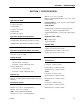
INTRODUCTION - MAINTENANCE SAFETY PRECAUTIONS SECTION A. INTRODUCTION - MAINTENANCE SAFETY PRECAUTIONS A.A GENERAL This section contains the general safety precautions which must be observed during maintenance of the aerial platform. It is of utmost importance that maintenance personnel pay strict attention to these warnings and precautions to avoid possible injury to themselves or others, or damage to the equipment. A maintenance program must be followed to ensure that the machine is safe to operate.
INTRODUCTION - MAINTENANCE SAFETY PRECAUTIONS REVISON LOG January 1999 - Original Issue March 16, 1999 - Revised May 30, 2001 - Revised December 14, 2001 - Revised January 17, 2002 - Revised May 15, 2002 - Revised b – JLG Lift – 3120762
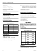
TABLE OF CONTENTS TABLE OF CONTENTS SUBJECT - SECTION, PARAGRAPH PAGE NO. SECTION A - INTRODUCTION - MAINTENANCE SAFETY PRECAUTIONS A.A A.B A.C General . . . . . . . . . . . . . . . . . . . . . . . . . . . . . . . . . . . . . . . . . . . . . . . . . . . . . . . . . . . . . . . . . . . . . .a Hydraulic System Safety . . . . . . . . . . . . . . . . . . . . . . . . . . . . . . . . . . . . . . . . . . . . . . . . . . . . . . . . .a Maintenance . . . . . . . . . . . . . . . . . . . . . . . . . . . . . . . .
TABLE OF CONTENTS (Continued) LIST OF FIGURES FIGURE NO. 1-1. 1-2. 2-1. 2-2. 2-3. 2-4. 2-5. 2-6. 2-7. 2-8. 2-9. 2-10. 2-11. 2-12. 2-13. 2-14. 2-15. 2-16. 2-17. 2-18. 2-19. 2-20. 2-21. 2-22. 3-1. 3-2. 3-3. 3-4. 3-5. TITLE PAGE NO. Serial Number Location. . . . . . . . . . . . . . . . . . . . . . . . . . . . . . . . . . . . . . . . . . . . . . . . . . . . . . . . . .1-4 Torque Chart . . . . . . . . . . . . . . . . . . . . . . . . . . . . . . . . . . . . . . . . . . . . . . . . . . . . . . . . . . . . . .
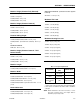
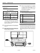
SECTION 1 - SPECIFICATIONS SECTION 1. SPECIFICATIONS 1.1 Optional - 5.00 x 16.00 - Solid, Rib CAPACITIES Optional (2046E3/2646E3/2658E3) - 7.50 x 16.00 - Solid, Flotation Tread Hydraulic Oil Tank PARKING BRAKE - Single cylinder, spring applied, hydraulically released 1532E3/1932E3 3.7 gallons (14.0 liters) DRIVE MOTORS 2033E3/2046E3 1532E3/1932E3 - 9.9 in[3] (160 cm[3]) displacement 3.35 gallons (12.7 liters) 2033E3 - 14.0 in[3] (225 cm[3]) displacement 2646E3/2658E3 3.35 gallons (12.
SECTION 1 - SPECIFICATIONS NOTE: If machine is equipped with optional pipe racks, maximum load on pipe racks is 100 lb. (45 kg). Maximum total capacity of pipe racks and platform combined is as follows: 2646E3/2658E3. Low Speed - 1.3 mph (2.1 kmh) Elevated Speed - 0.5 mph (0.80 kmh) Maximum Speed - 2.1 mph (3.4 kmh) 2033E3/2646E3 - 650 lb (295 kg) Gradeability 2046E3/2658E3- 900 lb (408 kg) All Models - 25% Manual Platform Extension Capacity Inside Turning Radius All Models - 250 lb.
SECTION 1 - SPECIFICATIONS Machine Height (Platform Fully Elevated) With Platform Elevated - (Pothole Protection System Lowered) 1532E3 - 15 ft (4.6 m) All Models - 0.75 in (1.9 cm) 1932E3 - 19 ft (5.8 m) 2033E3/2046E3 - 20 ft (6.1 m) Maximum Tire Load 2646E3/2658E3 - 26 ft (7.9 m) 1532E3 - 1,060 lb (481 kg) Machine Height (Platform Lowered) 1932E3 - 1,100 lb (499 kg) 1532E3 - 75.75 in. (1.9 m). 2033E3 - 1,410 lb (640 kg) 1932E3 - 79.75 in. (2.0 m). 2033E3/2046E3 - 79.0 in. (2.0 m).
SECTION 1 - SPECIFICATIONS 1.5 NOTE: Aside from JLG recommendations, it is not advisable to mix oils of different brands or types, as they may not contain the same required additives or be of comparable viscosities. If use of hydraulic oil other than Mobilfluid 424 is desired, contact JLG Industries for proper recommendations. LUBRICATION Hydraulic Oil Table 1-4. Hydraulic Oil HYDRAULIC SYSTEM OPERATING TEMPERATURE RANGE Lubrication Specifications SAE VISCOSITY GRADE Table 1-5.
SECTION 1 - SPECIFICATIONS 1.7 CYLINDER SPECIFICATIONS NOTE: All dimensions are given in inches (in), with the metric equivalent, centimeters (cm), given in parentheses. Table 1-6. Cylinder Specifications DESCRIPTION BORE STROKE ROD DIA Lift Cylinder (1532E3/ 1932E3) 3.00 (7.6) 30.38 (77.2) 2.00 (5.1) Lift Cylinder (2033E3/ 2046E3) 3.50 (8.9) 48.19 (122.40) 2.00 (5.1) Lift Cylinder (2646E3/ 2658E3) 4.00 (10.2) 48.44 (123.0) 2.50 (6.4) Steer Cylinder - All Models 1.50 (3.8) 6.35 (15.
Figure 1-2.
SECTION 2 - PROCEDURES SECTION 2. PROCEDURES 2.1 items must be maintained on a scheduled basis in order to function properly. GENERAL This section provides information necessary to perform maintenance on the scissor lift. Descriptions, techniques and specific procedures are designed to provide the safest and most efficient maintenance for use by personnel responsible for ensuring the correct installation and operation of machine components and systems. 2.
SECTION 2 - PROCEDURES 3. If a bearing is found to be serviceable, apply a light coat of oil and wrap it in clean (waxed) paper. Do not unwrap reusable or new bearings until they are ready to install. 4. Lubricate new or used serviceable bearings before installation. When pressing a bearing into a retainer or bore, apply pressure to the outer race. If the bearing is to be installed on a shaft, apply pressure to the inner race.
SECTION 2 - PROCEDURES 2. JLG recommends Mobilfluid 424, which has an SAE viscosity of 10W-30 and a viscosity index of 152 or, as an alternate, Kendall Hyken 052 hydraulic oil, which has an SAE viscosity of 10W-20 and a viscosity index of 152. Mobilfluid 424 and Kendall Hyken 052 are fully compatible, and can be mixed as necessary. NOTE: Start-up of hydraulic system with oil temperatures below -15 degrees F (-26 degrees C). is not recommended.
SECTION 2 - PROCEDURES Proportional Control Valves The proportional control valves provide a power output matching that required by the load. A small line connected to a load sensing port feeds load pressure back to a sequence valve. The sequence valve senses the difference between the load and pump outlet pressure, and varies the pump displacement to keep the difference constant.
SECTION 2 - PROCEDURES 4. There will be initial weeping of hydraulic fluid, which can be caught in a suitable container. After the initial discharge, there should not be any further leakage from the ports. If leakage continues at a rate of 6-8 drops per minute or more, the counterbalance valve is defective and must be replaced. 2. Carefully disconnect hydraulic hose from retract port of cylinder. There will be initial weeping of hydraulic fluid which can be caught in a suitable container.
SECTION 2 - PROCEDURES 2. Remove the bolt and locknut securing the cylinder rod attach pin to the upper inner arm assembly. Using a suitable brass drift, drive out the rod end attach pin from the arm assembly. 3. Retract the lift cylinder rod completely. 4. Tag and disconnect the hydraulic lines, then cap the lift cylinder hydraulic lines and ports. 5. Remove the bolt and locknut securing the barrel end attach pin to the lower arm assembly.
SECTION 2 - PROCEDURES Figure 2-2. Lift Cylinder Components Assembly DO NOT FU LLY EXTEN D CYLINDER TO END OF STROKE. RETRACT CYLINDER SLIGHTLY TO AVOID TRAPPING PRESSURE. 2. Operate the hydraulic power source and extend the cylinder. Shut down and disconnect the power source. Adequately support the cylinder rod, if necessary. 3. If applicable, remove the cartridge-type holding valve and fittings from the cylinder port block. Discard o-rings. Figure 2-3. Barrel Support 4.
SECTION 2 - PROCEDURES Figure 2-6. Tapered Bushing Removal Figure 2-4. Capscrew Removal 13. Screw the piston counter-clockwise, by hand, and remove the piston from the cylinder rod. EXTREME CARE SHOULD BE TAKEN WHEN REMOVING THE CYLINDER ROD, HEAD, AND PISTON. AVOID PULLING THE ROD OFFCENTER, WHICH COULD CAUSE DAMAGE TO THE PISTON AND CYLINDER BARREL SURFACES. 14. Remove and discard the piston o-rings, back-up rings, guidelock rings and hydrolock seals. 15.
SECTION 2 - PROCEDURES 11. Inspect seal and o-ring grooves in head for burrs and sharp edges. Dress applicable surfaces as necessary. 1. Using a special tool, pictured in the following illustration, install a new rod seal into the applicable cylinder head gland groove. Refer to the following illustration for the proper tool size. 12. Inspect cylinder head outside diameter for scoring or other damage and ovality and tapering. Replace as necessary. 13.
SECTION 2 - PROCEDURES Figure 2-10. Installation of Head Seal Kit Figure 2-12. Tapered Bushing Installation 7. Using suitable protection, clamp the cylinder rod in a vise or similar holding fixture as close to the piston as possible. 8. Carefully thread the piston on the cylinder rod hand tight, ensuring that the o-ring and back-up rings are not damaged or dislodged. 9. Thread the piston onto the rod until it abuts the spacer end and install the tapered bushing. 11.
SECTION 2 - PROCEDURES 2. Operate the hydraulic power source and extend the cylinder. Shut down and disconnect the power source. Adequately support the cylinder rod, if applicable. 3. Remove the cartridge-type holding valve and fittings from the cylinder port block. Discard o-rings. 4. Place the cylinder barrel into a suitable holding fixture. EXTREME CARE SHOULD BE TAKEN WHEN REMOVING THE CYLINDER ROD, HEAD, AND PISTON.
SECTION 2 - PROCEDURES Assembly ferential direction are acceptable provided they cannot cut the rod seal. Chrome should be present over the entire surface of the rod; the lack of chrome on the rod surface is unacceptable. If an unacceptable condition exists, repair or replace the rod. NOTE: Prior to cylinder assembly, ensure that the proper cylinder seal kit is used. Refer to the Illustrated Parts Manual. 3. Inspect the threaded portion of the rod for excessive damage. Dress the threads as necessary.
SECTION 2 - PROCEDURES 10. Remove the cylinder rod from the holding fixture. 3. Using a suitable pair of snap ring pliers, carefully remove the retaining ring from the cylinder barrel. 11. Install new seals and a new guidelock ring in the applicable outside diameter grooves of the piston. 4. Attach a suitable pulling device to the cylinder rod end. 12. Position the cylinder barrel in a suitable holding fixture. EXTREME CARE SHOULD BE TAKEN WHEN INSTALLING THE CYLINDER ROD, HEAD, AND PISTON.
SECTION 2 - PROCEDURES Figure 2-15. Brake Cylinder Assembly 9. Inspect cylinder guide outside diameter for scoring or other damage and ovality and tapering. Replace as necessary. 5. Carefully place the piston on the threaded end of the cylinder rod, ensuring that the o-ring is not damaged or dislodged. Push the piston onto the rod as far as it will go. 10. Inspect the oil ports for blockage or the presence of dirt or other foreign material. Repair as necessary. 6.
SECTION 2 - PROCEDURES 10. Continue pushing the rod into the barrel until the cylinder guide can be inserted into the cylinder barrel. 11. Using all applicable safety precautions, secure the cylinder rod assembly with a new retaining ring (12). 12. Reconnect the hydraulic hoses to the applicable cylinder ports. 10. Carefully remove cylinder rod section one from cylinder rod section two and carefully remove the piston from the cylinder rod. Remove and discard the piston seal and o-ring. 11.
SECTION 2 - PROCEDURES Figure 2-16. Steer Cylinder Repair 3. Carefully install the cylinder rod guide on rod section one, ensuring that the wiper ring and rod seal are not damaged or dislodged. Push the guide onto the rod section. 4. Place a new piston ring on the piston and a new oring on the threaded end of cylinder rod section two. EXTREME CARE SHOULD BE TAKEN WHEN INSTALLING THE CYLINDER ROD, CYLINDER ROD GUIDE, AND PISTON.
SECTION 2 - PROCEDURES 13. Carefully install the cylinder rod guide onto rod section two and slide the guide into the end of the cylinder barrel. 14. Coat the threads of the cylinder rod guide with Loctite #242 then secure the cylinder rod guide to the cylinder barrel using a suitable spanner wrench. 15. Reconnect the hydraulic hoses to the applicable cylinder ports. 2.
SECTION 2 - PROCEDURES Figure 2-18. Tilt Switch Leveling - Voltmeter Adjustment 3. While monitoring the pressure gauge at MP, adjust the lift up relief as follows: 2.16 LIMIT SWITCH ADJUSTMENT Platform Limit Switch 1532E3 - 1625 psi (112 bar). The platform limit switch is located on the left side of the frame of the machine. When activated, the switch cuts out the High Drive function. Adjust the switch to activate when the platform is raised above the stowed position. 1932E3 - 2000 psi (138 bar).
SECTION 2 - PROCEDURES Steer Adjustment check steer right pressure. If necessary, adjust steer right pressure to 2100 psi (145 bar). 1. If necessary, connect a pressure gauge to gauge port MP. 2. Activate drive by pressing the drive switch and activating the controller to the full forward position. While holding the controller, activate steer right and 3. Activate drive by pressing the drive switch and activating the controller to the full forward position.
SECTION 2 - PROCEDURES Figure 2-20. Drive Motor (Sauer Danfoss) 4. With the housing in the holding device, press the shaft out of the housing. Collect the needle bearings for possible re-use. 2.18 DRIVE MOTOR (SAUER DANFOSS) Dismantling 1. Place motor in proper holding device that allows access to the output shaft. 2. Carefully remove end cover sideways being sure to catch any parts that may fall from the gearwheel. 3. The needles bearings will fall out during dismantling and can be collected and reused.
SECTION 2 - PROCEDURES Assembly 9. Place the needles in the outer ring and hold them in place with grease. Carefully place the distributor plate on the bearing housing so that the shaft enters the bearing. Press the distributor plate until it stops on the housing and line up the screw holes. NOTE: Before assembly, inspect all parts and replace if necessary. Before assembly, lubricate all parts with hydraulic oil and grease rubber parts with vasoline. 1. Turn motor housing so the rear end faces upwards.
SECTION 2 - PROCEDURES 2.19 POTHOLE PROTECTION SYSTEM LIMIT SWITCH Adjustment 1. With the pothole protection system in the fully down position, mount the limit switch on the bracket in the rear of the machine frame. 2. Adjust the switch to provide for 1/16 inch maximum clearance between the roller and the cam. WHEN MOUNTING OR ADJUSTING THE LIMIT SWITCH, BE SURE THAT THE SAFETY PROP IS BEING USED PROPERLY. 3. Tighten the switch mounting hardware. 2.
SECTION 2 - PROCEDURES The JLG SMART System™ controller has a built in LED to indicate any faults. The system stores recent faults which may be accessed for troubleshooting. Optional equipment includes an hourmeter, beacon light, tilt switch (light and/or alarm), power deck, power deck extension limit, function cutout, and ground alarm. These options may be added later but some must be programmed into the motor controller when installed.
SECTION 2 - PROCEDURES Changing the Access Level of the Hand Held Analyzer: When the analyzer is first connected, you will be in access level 2 which enables you to only view most configuration settings which cannot be changed until you enter a password to advance to a lower level. This ensures that a setting cannot be accidentally altered. To change the access level, the correct password must be entered. To enter the password, scroll to the ACCESS LEVEL menu.
Figure 2-22.
SECTION 2 - PROCEDURES 2.21 MACHINE PERSONALITY SETTINGS Table 2-2. Machine Personality Settings PERSONALITY MIN MAX DRIVE-ACCEL 0.5 SEC 5.0 SEC DRIVE-DECEL 0 SEC 5.0 SEC DRIVE CREEP 1% 25.0% DRIVE SPEED MAX (LOW) 50% 100% DRIVE SPEED MAX (HIGH) 50% 100% *ELEVATION MAX *0% *40% *POSI-TRAC TIME *0 Sec *60 Sec *50 Amp *200 Amp 0 Sec 25 Sec LIFT ACCEL 0.5 Sec 5.0 Sec LIFT DECEL 0.0 Sec 1.5 Sec LIFT CREEP 1% 25% LIFT UP MAX 50% 100% MAX DOWN 30% 100% DECK ACCEL 0.
SECTION 2 - PROCEDURES 2.22 MACHINE MODEL DEFAULT SETTINGS Table 2-3. Machine Model Default Settings Chart Adjustment 1532E3 1932E3 2033E3 2046E3 2646E3 2658E3 DRIVE ACCELERATION 1.0 sec 1.0 sec 1.0 sec 1.0 sec 1.0 sec 1.0 sec DRIVE DECELERATION 0.5 sec 0.5 sec 0.5 sec 0.5 sec 0.5 sec 0.
SECTION 2 - PROCEDURES 2.23 MACHINE CONFIGURATION INFORMATION NOTE: The following information is to be used when working with the MACHINE SETUP menu. When configuring the E Series scissor lift, the machine configuration must be completed before any personality settings can be changed. Changing the personality settings first and then changing the model number of the machine configuration will cause the personality settings to return to default values . Table 2-4.
SECTION 2 - PROCEDURES Table 2-4. Machine Configuration Programming Information Configuration Digit Number 5 (FUNCTION CUTOUT) 0 No function cutout installed. 1 Overload switch for French, Japanese machines. — Cuts out all functions. Sounds platform alarm for two seconds on, two seconds off, while operator tries to perform the function that has been cut out (provided the platform alarm is installed). 0 No ground alarm installed. 1 Descent alarm. — Sounds when LIFT DOWN is active.
SECTION 2 - PROCEDURES 2.24 JLG SMART SYSTEM™ HELP MESSAGES AND FLASH CODES Table 2-5. Help Messages NO FLASH CODE IS INDICATED FOR THE FOLLOWING HELP MESSAGES; THEY ARE INTENDED TO HINT AT A POSSIBLE PROBLEM IF THE MACHINE IS NOT BEHAVING AS EXPECTED EVERYTHING OK The "normal" help message in platform mode. GROUND MODE OK The “normal” help message in ground mode. ALARM SOUNDING: ARMGAURD PROTECTION ACTIVE Arm guard protection has tripped during lift down and is preventing lift down for three seconds.
SECTION 2 - PROCEDURES Table 2-6. JLG SMART System™ Help Messages & Flash Codes Code Description 2-1 - Indicates problems with EMS inputs STARTUP - Neither EMS is active - the system is just switching on or is discharging the capacitor bank. A welded line contactor might also cause this.
SECTION 2 - PROCEDURES Table 2-6. JLG SMART System™ Help Messages & Flash Codes Code Description 3-3 - Indicates that a contactor coil is short-circuit SHORT-CIRCUIT LINE CONTACTOR COIL - The line contactor was not energized when required, due to coil over current protection. VALVE OR LINE CONTACTOR ENERGIZED - CHECK WIRING - The drive circuit to the line contactor or a valve is active when no driver circuit is turned on (this could be due to a wiring error to the valves or line contactor).
SECTION 2 - PROCEDURES between items in the same level. The UP/DOWN arrow keys alter a value if allowed 2.25 ANALYZER MENU STRUCTURE In the following structure descriptions, an intended item is selected by pressing ENTER; pressing ESC steps back to the next outer level. The LEFT/RIGHT arrow keys move Table 2-7.
SECTION 2 - PROCEDURES Table 2-7.
SECTION 2 - PROCEDURES Table 2-7.
SECTION 2 - PROCEDURES Table 2-7.
SECTION 2 - PROCEDURES Table 2-7.
SECTION 2 - PROCEDURES Table 2-7. Analyzer Menu Structure TOP LEVEL MENU SUB LEVEL MENU ITEM TO BE VIEWED OR CHANGED DESCRIPTION DISPLAY MACHINE SETUP MODEL NUMBER Displays/adjusts machine model NOTE: All personalities reset to default when model number is altered TILT SWITCH Displays/adjusts tilt switch presence/function POWER DECK Displays/adjusts power deck presence DECK EXT.
SECTION 2 - PROCEDURES 2.26 PREVENTIVE MAINTENANCE AND INSPECTION SCHEDULE The preventive maintenance and inspection checks are listed and defined in the following table. This table is divided into two basic parts, the “AREA” to be inspected and the “INTERVAL” at which the inspection is to take place. Under the “AREA” portion of the table, the various systems along with the components that make up that system are listed.
SECTION 2 - PROCEDURES Table 2-8. Preventive Maintenance and Inspection Schedule AREA INTERVAL DAILY WEEKLY MONTHLY 3 MONTH 6 MONTH 1 YEAR PLATFORM 1. Controller 1,11 2. Switches 1,11 3. Placards and Decals 1,2 4. Control Tags 1,2 5. Hose and Cable 4,8 6. Wear Pads 7. Handrail and Chains 8 1,4 CHASSIS 1. Batteries 3 2. Battery Charger 1 3. Hydraulic Pump/Motor 1 5 4. Valves 1 5 5. Hydraulic Filter (See Lubrication Chart) 5 6. Hydraulic hoses and Tubing 1 7.
SECTION 3 - TROUBLESHOOTING SECTION 3. TROUBLESHOOTING 3.1 GENERAL 3.3 This section contains troubleshooting information to be used for locating and correcting most of the operating problems which may develop in the aerial platform. If a problem should develop which is not presented in this section or which is not corrected by listed corrective actions, technically qualified guidance should be obtained before proceeding with any maintenance. 3.
SECTION 3 - TROUBLESHOOTING Table 3-1. Hydraulic System Troubleshooting TROUBLE Hydraulic pump noisy REMEDY Air bubbles in oil (Reservoir too low) Replenish oil as necessary Oil filter dirty Clean and/or replace filter as necessary Oil in reservoir low Replenish oil as necessary Restricated reservoir air vent Clean vent Oil viscosity too high Drain system and replace with recommended oil.Rrefer to Hydraulic Oil Table Oil viscosity too high Drain system and replace with recommended oil.
SECTION 3 - TROUBLESHOOTING LIFT RELIEF SET @ ( SEE MANUAL PER MODEL) STEER RELIEF SET @ 2100 PSI Figure 3-1.
SECTION 3 - TROUBLESHOOTING U3 JLG SMART SYSTEM MICROPROCESSOR Figure 3-2.
SECTION 3 - TROUBLESHOOTING U3 JLG SMART SYSTEM MICROPROCESSOR 1282880 L Figure 3-3.
SECTION 3 - TROUBLESHOOTING BEACON MOTOR 327 PLATFORM CONSOLE BOX TO LINE CONTACTOR RELAY LINE CONTACTOR RELAY WORK LIGHT VALVE TO BATTERIES + ALARM HORN TEMPERATURE SWITCH Figure 3-4.
SECTION 3 - TROUBLESHOOTING BATTERY CHARGER 5 HAND HELD ANALYZER TILT ALARM PLATFORM DESCENT DELAY (EURO) TO LINE CONTACTOR RELA Y FROM J2 VALVE HARNESS GROUND CONTROLS POT-HOLE PROTECTION SYSTEM CHARGER MACHINE LOCKOUT (AUSTRALIAN ONLY) DRIVE CUT-OUT LIFT DOWN SOLENOID DECK EXTENSION CUT-OUT ELEVATION SWITCH (HI-DRIVE LIMIT) OVERLOAD PRESSURE SWITCH (JAPANESE/ FRENCH SPEC) Figure 3-5.
SECTION 3 - TROUBLESHOOTING This page left blank intentionally.
Corporate Office JLG Industries, Inc. 1 JLG Drive McConnellsburg PA. 17233-9533 USA Phone: (717) 485-5161 Fax: (717) 485-6417 JLG Worldwide Locations JLG Industries (Australia) P.O. Box 5119 11 Bolwarra Road Port Macquarie N.S.W.