Operation & Safety Manual Keep this manual with machine at all times.
Revision Log Revision Log REVISION LOG October 23, 2008 - A - Original Issue of Manual April 29, 2009 - B - Revised pages 2-3, 2-4 & 2-5.
Read This First Read This First This manual is a very important tool! Keep it with the machine at all times. The purpose of this manual is to provide owners, users, operators, lessors, and lessees with the precautions and operating procedures essential for the safe and proper machine operation for its intended purpose. Due to continuous product improvements, JLG Industries, Inc. reserves the right to make specification changes without prior notification. Contact JLG Industries, Inc.
Read This First This product must comply with all safety related bulletins. Contact JLG Industries, Inc. or the local authorized JLG representative for information regarding safetyrelated bulletins which may have been issued for this product. JLG Industries, Inc. sends safety related bulletins to the owner of record of this machine. Contact JLG Industries, Inc. to ensure that the current owner records are updated and accurate. JLG Industries, Inc.
Read This First Other Publications Available For detailed machine operation procedures and safety information, please refer to the appropriate machine Operation & Safety Manual. Note: The following standards may be referenced in this manual: ANSI is compliant to ANSI/ITSDF B56.6 AUS is compliant to AS 1418.19 CE is compliant to EN1459 Refer to the machine Serial Number Plate to identify the applicable compliance standard.
Table of Contents Table of Contents TABLE OF CONTENTS Revision Log Read This First Operator Qualifications ...................................................... b Modifications ...................................................................... b Other Publications Available .............................................. d Table of Contents Section 1 - General Safety Practices 1.1 Hazard Classification System ..............................................
Table of Contents Section 3 - Machine Operation 3.1 Operating With A Suspended Load..................................... 3-1 Lift Load Safely............................................................... 3-1 Picking Up A Suspended Load....................................... 3-1 Transporting a Suspended Load .................................... 3-2 Leveling Procedure......................................................... 3-2 Placing a Suspended Load.............................................
Section 1 - General Safety Practices SECTION 1 - GENERAL SAFETY PRACTICES 1.1 HAZARD CLASSIFICATION SYSTEM Safety Alert System and Safety Signal Words DANGER OW0010 DANGER indicates an imminently hazardous situation which, if not avoided, will result in death or serious injury. WARNING OW0021 WARNING indicates a potentially hazardous situation which, if not avoided, could result in death or serious injury.
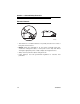
Section 1 - General Safety Practices 1.3 OPERATION SAFETY Electrical Hazards 10 FT (3 M) OW0040 • This machine is not insulated and does not provide protection from contact or being near electrical current. • NEVER operate the telehandler in an area where overhead power lines, overhead or underground cables, or other power sources may exist without ensuring the appropriate power or utility company de-energizes the lines. • Always check for power lines before raising the boom.
Section 1 - General Safety Practices Tip Over Hazard General • For additional load requirements, refer to the appropriate capacity chart. OW0050 • Never use an attachment without the appropriate JLG approved capacity chart installed on the telehandler. • Understand how to properly use the capacity charts located in cab. • DO NOT exceed rated lift capacity. • Be sure that the ground conditions are able to support the machine.
Section 1 - General Safety Practices OH2291 • MAINTAIN proper tire pressure at all times. If proper tire pressures are not maintained, this machine could tip over. • Refer to manufacturer’s specifications for proper fill ratio and pressure requirements for tires equipped with ballast. OH20911 • Always wear the seat belt. • Keep head, arms, hands, legs and all other body parts inside operator’s cab at all times.
Section 1 - General Safety Practices Suspended Load OW0150 • Tether suspended loads to restrict movement. • DO NOT raise the load more than 300 mm (11.8 in) above ground surface or the boom more than 45°. • Weight of all rigging (slings, etc.) must be included as part of load. • Start, travel, turn and stop slowly to prevent load from swinging. • When driving with the boom raised, DO NOT exceed walking speed. • Beware of wind.
Section 1 - General Safety Practices Travel Hazard 2-Wheel Front Steer 4-Wheel Circle Steer 4-Wheel Crab Steer OAL2030 • Steering characteristics differ between steer modes. Identify the steer mode settings of the telehandler being operated. • Ensure that adequate clearance is provided between both rear tail swing and front fork swing. • Look out for and avoid other personnel, machinery and vehicles in the area. Use a spotter if you DO NOT have a clear view.
Section 1 - General Safety Practices Load Falling Hazard OW0130 • Never suspend load from forks or other parts of carriage. • DO NOT burn or drill holes in fork(s). • Forks must be centered under load and spaced apart as far as possible.
Section 1 - General Safety Practices Lifting Personnel OW0170 • When lifting personnel, USE ONLY a JLG approved personnel work platform, with proper capacity chart displayed in the cab. OW0190 • DO NOT drive machine from cab when personnel are in platform.
Section 1 - General Safety Practices Driving Hazards on Slopes OW0200 To maintain sufficient traction and braking capabilities, travel on slopes as follows: • When unloaded, the rear of the machine is the “heavy end.” Drive with forks pointed downhill. • When loaded, the front of the machine is the “heavy end.” Drive with the forks pointed uphill. • For additional travel requirements, refer to the appropriate capacity chart.
Section 1 - General Safety Practices Pinch Points and Crush Hazards Stay clear of pinch points and rotating parts on the telehandler. OW0210 • Stay clear of moving parts while engine is running. OW0220 • Keep clear of steering tires and frame or other objects. OW0230 • Keep clear from under boom.
Section 1 - General Safety Practices OW0240 • Keep clear of boom holes. OW0250 • Keep arms and hands clear of attachment tilt cylinder. OW0260 • Keep hands and fingers clear of carriage and forks. OW0960 • Keep others away while operating.
Section 1 - General Safety Practices Fall Hazard OW0280 • Enter using the proper hand holds and steps provided. Always maintain 3-point contact when mounting or dismounting. Never grab control levers or steering wheel when mounting or dismounting the machine. • DO NOT get off the machine until the shutdown procedure has been performed. OW0290 • DO NOT carry riders. Riders could fall off machine causing death or serious injury.
Section 1 - General Safety Practices Chemical Hazards Exhaust Fumes • DO NOT operate machine in an enclosed area without proper ventilation. • DO NOT operate the machine in hazardous environments unless approved for that purpose by JLG and site owner. Sparks from the electrical system and the engine exhaust can cause an explosion. • If spark arrestors are required, ensure they are in place and in good working order.
Section 1 - General Safety Practices This Page Intentionally Left Blank 1-14 31200487
Section 2 - Load Management Indicator System (LMIS) SECTION 2 - LOAD MANAGEMENT INDICATOR SYSTEM (LMIS) 2.1 GENERAL The LMIS provides visual indication of stability limitations by monitoring suspended loads compared to predetermined capacity charts. Note: When using non-suspended load type attachments, capacity charts located in the operator cab must be used. Refer to the machine Operation & Safety Manual for details.
Section 2 - Load Management Indicator System (LMIS) 2.2 CONTROL PANEL The control panel displays information and allows for the selection of different attachments. 4 3 5 2 1 6 + OZ3091 1. UP Button - Depress to scroll up inside a menu. 2. DOWN Button - Depress to scroll down inside a menu. 3. Display - Shows working data. See page 2-3. 4. Status Lights - Progressively illuminate (two green, yellow then red) to indicate lifting conditions. See page 2-6. 5. ENT Button - Depress to confirm an action.
Section 2 - Load Management Indicator System (LMIS) Display 1 2 3 4 5 6 0 OFF a c b 0.0 m 0.0 m 0.0 d d OZ3410 0.0 m 0.0 t 7 8 max 0.0 t XXXXX XXXXX 9 10 11 1. Attachment - Current attachment selection (see page 2-5). a. OFF - Select when lifting a non-suspended load. Minimal information shown on display. Capacity charts located in the operator cab must be used. b. Truss Boom attachment selected. 2. Operating Mode c. Outriggers fully engaged. d. Outriggers not engaged. 3.
Section 2 - Load Management Indicator System (LMIS) 2.3 OPERATION System Start Up 0 0.0 m 0.0 m 0.0 d 0.0 m OZ3081 0.0 max 0.0 t t 2 1 ST02 Date JLGXXXX 1. When the machine is started the system automatically switches on, performs a self-test and briefly shows the machine model (1) and LMIS software version (2) (dd.mm.yy = software date of development). 0 4 5 0.0 m 0.0 m 0.0 d 0.0 m 0.0 max 0.0 t t OZ3180 2.
Section 2 - Load Management Indicator System (LMIS) Attachment Selection The machine can operate with various attachments, but the appropriate capacity chart must be selected by the operator. When an attachment is changed, the LMIS must be manually set to the corresponding attachment capacity chart. 1. Escape out of all menus. 2. Press the UP button. 0 2 3 0.0 m 0.0 m 0.0 d 0.0 m OZ3190 0.0 max 0.0 t t XXXXXXXXXXA XXXX XXXX 1 3.
Section 2 - Load Management Indicator System (LMIS) Lifting Conditions and Alarms The control panel and external audible beacon tower (if equipped) display machine operating conditions. 1 2 3 4 3 2 0 0.0 m 0.0 m 0.0 d 0.0 m + 0.0 max 0.0 t 1 t - OZ3121 VIEW OF EXTERNAL AUDIBLE BEACON TOWER (IF EQUIPPED) 1. Green Light - Illuminates when load is less than rated capacity. 2. Yellow Light - Illuminates and intermittent alarm sounds when load is approaching rated capacity. 3.
Section 2 - Load Management Indicator System (LMIS) 2.4 DIAGNOSTIC DATA By pressing ENT, the display shows sub-menus. To enter a sub-menu, wait 2-3 seconds on the selected menu. Alarms and Warnings The first menu displays the Alarm and Warning Codes. P01 : Alarms In this menu, the Alarm code and Warning codes are shown. See page 5-2 for listing of codes. Alarms : XXXX Warning : XXXX LMI Values The second menu displays the LMI Values.
Section 2 - Load Management Indicator System (LMIS) Pressure Values The third menu displays Pressure Values. P03 : Pressures In this menu the following values are shown: • P - Differential pressure of the Lift cylinder (bar). • L - Pressure in the piston side of the Lift cylinder (bar). • H - Pressure in the rod side of the Lift cylinder (bar). • p - Differential pressure in the Compensation cylinder (bar). • l - Pressure in the piston side of Compensation cylinder (bar).
Section 2 - Load Management Indicator System (LMIS) LMI Status The fifth menu displays information relative to LMI status. P17 : Lmi Status P17 : Lmi Status I 0 : OFF 1. Press ESC to enter the sub-menu. * X I : value 2. Press ESC to move the (*). 3. Press DOWN to decrease the item selected. 4. Press UP to increase the item selected.
Section 2 - Load Management Indicator System (LMIS) 2-10 31200487
Section 3 - Machine Operation SECTION 3 - MACHINE OPERATION 3.1 OPERATING WITH A SUSPENDED LOAD Lift Load Safely • You must know the weight and load center of every load you lift. If you are not sure of the weight and load center, check with your supervisor or with the supplier of the material. WARNING TIP OVER HAZARD. Exceeding lift capacity of the telehandler could damage the equipment and/or cause tip over resulting in death or serious injury.
Section 3 - Machine Operation Transporting a Suspended Load OZ3160 OW0130 • Travel in accordance with the requirements set forth in Section 1 - General Safety Practices and Section 4 - Attachments. • For additional requirements, refer to the appropriate capacity chart. Important things to remember: • Ensure the boom is fully retracted. • Never raise the load more than 300 mm (11.8 in) above ground surface or the boom more than 45°.
Section 3 - Machine Operation Placing a Suspended Load Before placing any load be sure that: • The landing point can safely support the weight of the load. • The landing point is level; front to back and side to side. • Use the capacity chart to determine safe boom extension range. See “Use of the Capacity Chart” on page 4-1. • Align load at the level load is to be placed, then position boom slowly until load is just above area where it is to be placed.
Section 3 - Machine Operation This Page Intentionally Left Blank 3-4 31200487
Section 4 - Attachments SECTION 4 - ATTACHMENTS 4.1 USE OF THE CAPACITY CHART To properly use the capacity chart (see page 4-2), the operator must first determine and/or have the following: 1. A JLG approved attachment. 2. The proper Capacity Chart. 3. Weight of the load being lifted. 4. Load placement information: a. HEIGHT where the load is to be placed. b. DISTANCE from the front tires of the telehandler where the load is to be placed. 5.
Section 4 - Attachments Sample Capacity Chart This Capacity Chart may be used with this model ONLY. The model of your telehandler is indicated on the boom or chassis. Model XXXX is used for demonstration purposes only. These numbers must match the model/option number stamped on the attachment ID Plate. XXXX P/N XXXXXXXX Travelling Information TRAVELLING (PICK & CARRY) REQUIRES LOAD ON HOOK. MAX TRAVEL WITH RATED LOAD XX M/S. (WALKING SPEED). BOOM FULLY RETRACTED.
Section 4 - Attachments To identify the proper capacity chart on telehandlers equipped with outriggers, refer to the following icons which may be located on the capacity chart. • Use when lifting a load with outriggers up. OW0930 • Use when lifting a load with outriggers down.
Section 4 - Attachments Example A contractor owns a model xxxx telehandler with a truss boom. He knows this attachment may be used with his model since: • The attachment model/option number, matches the attachment number on the capacity chart. • The capacity chart is clearly marked for model xxxx and corresponds with machine configuration being used. • The capacity chart part number is available and selected on the LMIS.
Section 4 - Attachments Truss Boom Description P/N Truss Boom 2 m - 4000 kg.........................................1001101442 OZ3420 Use Truss Boom Capacity Chart Suspend loads in accordance with requirements set forth in Section 1 - General Safety Practices. The joystick (1) controls movement of the boom. The attachment tilt roller switch (2) controls truss boom tilt. • Push roller switch down to tilt up. • Push roller switch up to tilt down.
Section 4 - Attachments This Page Intentionally Left Blank 4-6 31200487
Section 5 - LMIS Service and Maintenance SECTION 5 - LMIS SERVICE AND MAINTENANCE 5.1 AUTO-DIAGNOSTIC SYSTEM The LMIS is equipped with an auto-diagnostic system which is able to detect faulty pressure transducers, boom angle/length sensors, broken cables or internal electronic faults. When the alarm sounds, the display shows an alarm message. If an alarm code sounds apply the park brake, shift the transmission into “Neutral”, lower forks or attachment to the ground and shut off the engine.
Section 5 - LMIS Service and Maintenance Alarm Codes Alarm Code Description 1 Memory Data Not Reliable 2 Angle Sensor 1 reading lower than minimum value 3 Angle Sensor 1 reading higher than maximum value 4 Reading of boom length sensor 1 lower than minimum value 5 Reading of boom length sensor 1 higher than maximum value 10 Reading pressure of Lift cylinder (bottom side) lower than minimum value 11 Reading pressure of the Lift cylinder (bottom side) higher than maximum value 12 Reading pres
An Oshkosh Corporation Company JLG Industries, Inc. 1 JLG Drive McConnellsburg PA. 17233-9533 USA Phone: +1-717-485-5161 Customer Support Toll Free: 1-877-554-5438 Fax: +1-717-485-6417 JLG Worldwide Locations JLG Industries (Australia) P.O. Box 5119 11 Bolwarra Road Port Macquarie N.S.W. 2444 Australia Phone: +61 265 811 111 Fax: +61 265 810 122 JLG Latino Americana Ltda. Rua Eng.