Operation & Safety Manual Model 25RTS 33RTS 40RTS 3120690 May 15, 2003
– JLG Sizzor –
This page left blank intentionally.
FOREWORD FOREWORD This manual is a very important tool! Keep it with the machine at all times. The purpose of this manual is to provide owners, users, operators, lessors, and lessees with the precautions and operating procedures essential for the safe and proper machine operation for its intended purpose. Due to continuous product improvements, JLG Industries, Inc. reserves the right to make specification changes without prior notification. Contact JLG Industries, Inc. for updated information.
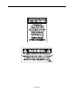
FOREWORD SAFETY ALERT SYMBOLS AND SAFETY SIGNAL WORDS This is the Safety Alert Symbol. It is used to alert you to the potential personal injury hazards. Obey all safety messages that follow this symbol to avoid possible injury or death INDICATES AN IMMINENTLY HAZARDOUS SITUATION WHICH, IF NOT AVOIDED, WILL RESULT IN SERIOUS INJURY OR DEATH. ON THE MACHINE THIS WILL HAVE A RED BACKGROUND. INDICATES A POTENTIALITY HAZARDOUS SITUATION WHICH, IF NOT AVOIDED, COULD RESULT IN SERIOUS INJURY OR DEATH.
FOREWORD THIS PRODUCT MUST COMPLY WITH ALL SAFETY RELATED BULLETINS. CONTACT JLG INDUSTRIES, INC. OR THE LOCAL AUTHORIZED JLG REPRESENTATIVE FOR INFORMATION REGARDING SAFETY-RELATED BULLETINS WHICH MAY HAVE BEEN ISSUED FOR THIS PRODUCT. MODIFICATION OR ALTERATION OF AN AERIAL WORK PLATFORM SHALL BE MADE ONLY WITH WRITTEN PERMISSION FROM THE MANUFACTURER IMPORTANT JLG INDUSTRIES, INC. SENDS SAFETY RELATED BULLETINS TO THE OWNER OF RECORD OF THIS MACHINE. CONTACT JLG INDUSTRIES, INC.
FOREWORD REVISION LOG Original Issue Revised Revised Revised Revised Revised Revised Revised 8 - March 1, 1993 May 23, 1999 July 22, 1999 September 2, 1999 October 29, 1999 May 5, 2000 October 15, 2001 May 15, 2003 – JLG Lift – 3120690
TABLE OF CONTENTS TABLE OF CONTENTS SUBJECT - SECTION, PARAGRAPH SECTION - SECTION - FOREWORD PAGE NO. SECTION 1 - SAFETY PRECAUTIONS 1.1 1.2 1.3 1.4 1.5 General . . . . . . . . . . . . . . . . . . . . . . . . . . . . . . . . . . . . . . . . . . . . . . . . . . . . . . . . . . . . . . . . . . . . . .1-1 Pre-operation. . . . . . . . . . . . . . . . . . . . . . . . . . . . . . . . . . . . . . . . . . . . . . . . . . . . . . . . . . . . . . . . . .1-1 Operation. . . . . . . . . . . . . . . . . . . . . .
TABLE OF CONTENTS (Continued) LIST OF FIGURES FIGURE NO. 2-1. 2-2. 2-3. 2-4. 2-5. 3-1. 3-2. 3-3. 4-1. TITLE PAGE NO. Walk-Around Inspection Diagram . . . . . . . . . . . . . . . . . . . . . . . . . . . . . . . . . . . . . . . . . . . . . . . . . .2-4 Walk-Around Inspection Points (Sheet 1 of 2) . . . . . . . . . . . . . . . . . . . . . . . . . . . . . . . . . . . . . . . .2-5 Walk-Around Inspection Points (Sheet 2 of 2) . . . . . . . . . . . . . . . . . . . . . . . . . . . . . . . . . . . . . . . .
SECTION 1 - SAFETY PRECAUTIONS SECTION 1. SAFETY PRECAUTIONS 1.1 • Do not operate this machine until complete training is performed by authorized persons. GENERAL This section outlines the necessary precautions for proper and safe machine usage and maintenance. For proper machine use, it is mandatory that a daily routine is established based on the content of this manual.
SECTION 1 - SAFETY PRECAUTIONS Machine Inspection • Before machine operation, perform inspections and functional checks. Refer to Section 2 of this manual for detailed instructions. • Do not operate this machine until it has been serviced and maintained according to requirements specified in the Service and Maintenance Manual. • Be sure all safety devices are operating properly. Modification of these devices is a safety violation.
SECTION 1 - SAFETY PRECAUTIONS • Platform-to-structure transfers at elevated positions are discouraged. Where transfer is necessary, enter/exit through the gate only with the platform within 1 foot (0.3m) of a safe and secure structure. 100% tie-off is also required in this situation using two lanyards. One lanyard must be attached to the platform with the second lanyard attached to the structure.
SECTION 1 - SAFETY PRECAUTIONS • Do not raise the platform or drive from an elevated position unless the machine is on firm, level surfaces and evenly supported. • Keep the chassis of the machine at least 2 ft. (0.6m) from holes, bumps, drop-offs, obstructions, debris, concealed holes, and other potential hazards on the floor/surface unless approved by JLG.
SECTION 2 - PREPARATION AND INSPECTION SECTION 2. PREPARATION AND INSPECTION 2.1 GENERAL 2.3 This section provides the necessary information needed by those personnel that are responsible to place the machine in operation readiness, and lists checks that are performed prior to use of the machine. It is important that the information contained in this section be read and understood before any attempt is made to operate the machine.
SECTION 2 - PREPARATION AND INSPECTION Frame Steer Linkage No visible damage; loose or missing hardware (top and underside). No loose or missing parts; no visible damage. Drive Hubs No excessive wear; no damage. Check oil level in drive hub by removing pipe plug and feeling for oil level. (Contact service personnel for assistance if needed.) Control Boxes (Console and Ground) Steer Spindle Assemblies Switches operable; no visible damage; placards secure and legible.
SECTION 2 - PREPARATION AND INSPECTION 2.4 Machine Log DAILY WALK-AROUND INSPECTION It is the users responsibility to inspect the machine before the start of each workday. It is recommended that each user inspect the machine before operation, even if the machine has already been put into service under another user. This Daily Walk-Around Inspection is the preferred method of inspection.
SECTION 2 - PREPARATION AND INSPECTION Figure 2-1.
SECTION 2 - PREPARATION AND INSPECTION GENERAL Begin the “Walk-Around Inspection” at Item 1, as noted on the diagram.Continue to the right (counterclockwise viewed from top) checking each item in sequence for the conditions listed in the “Walk-Around Inspection Checklist”. 11. Hydraulic Filter - No visible damage, properly secured, no evidence of leakage. 12. Control Valves - Valves properly secured, no visible damage, no evidence of leakage.
SECTION 2 - PREPARATION AND INSPECTION 28. Drive Motor, Right Rear - No visible damage, no evidence of leakage. 29. Drive Brake, Right Rear - No loose or missing parts, no visible damage, no evidence of leakage. 30. Drive Hub, Right Rear - No visible damage, no evidence of leakage. Drive hubs should be one half full of EPGL SAE 90. 31. Drive Wheel and Tire Assembly, Left Rear - Properly secured no loose or missing lug nuts, no visible damage. Refer to inflation psi stenciled on frame or wheel rims. 32.
SECTION 2 - PREPARATION AND INSPECTION 2.5 DAILY FUNCTIONAL CHECK 2.6 TO AVOID SERIOUS INJURY, DO NOT OPERATE MACHINE IF ANY CONTROL LEVERS OR TOGGLE SWITCHES CONTROLLING PLATFORM MOVEMENT DO NOT RETURN TO THE OFF POSITION WHEN RELEASED. A functional check of all systems should be performed, under no load, once the walk-around inspection is complete, in an area free of overhead and ground level obstructions. Perform pre-load functional check in accordance with the following procedure: 1.
Figure 2-4.
SECTION 2 - PREPARATION AND INSPECTION Table 2-1.
SECTION 2 - PREPARATION AND INSPECTION 2.7 4. As the engine begins to stumble place the switch to the LPG position, allowing the LP fuel to be sent to the fuel regulator. DUAL FUEL SYSTEM IT IS POSSIBLE TO SWITCH FROM ONE FUEL SOURCE TO THE OTHER WITHOUT ALLOWING THE ENGINE TO STOP. EXTREME CARE MUST BE TAKEN AND THE FOLLOWING INSTRUCTIONS MUST BE FOLLOWED. Changing from Gasoline to LP Gas 1. Start the engine from the ground control station. 2.
Figure 2-5.
SECTION 2 - PREPARATION AND INSPECTION This page intentionally left blank.
SECTION 3 - USER RESPONSIBILITIES AND MACHINE CONTROL SECTION 3. USER RESPONSIBILITIES AND MACHINE CONTROL 3.1 GENERAL IMPORTANT SINCE THE MANUFACTURER HAS NO DIRECT CONTROL OVER MACHINE APPLICATION AND OPERATION, CONFORMANCE WITH GOOD SAFETY PRACTICES IN THESE AREAS IS THE RESPONSIBILITY OF THE USER AND HIS OPERATING PERSONNEL. This section provides the necessary information needed to understand control functions.
SECTION 3 - USER RESPONSIBILITIES AND MACHINE CONTROL Placards Ground Control Station Important points to remember during operation are provided at the control stations by DANGER, WARNING, CAUTION, IMPORTANT and INSTRUCTION placards. This information is placed at various locations for the express purpose of alerting personnel of potential hazards constituted by the operating characteristics and load limitations of the machine. See foreword for definitions of the above placards.
SECTION 3 - USER RESPONSIBILITIES AND MACHINE CONTROL Figure 3-1. Ground Control Station 6. Choke Switch - (If Equipped) - A momentary contact, push-button type switch supplies power to the choke solenoid, when depressed, to assist cold start operation. 7. Gasoline/LPG Select Switch - (Dual Fuel Only) A three position toggle-type switch is used to select the desired method of powering the unit.
SECTION 3 - USER RESPONSIBILITIES AND MACHINE CONTROL Figure 3-2. Platform Control Station Platform Control Station 1. Enable Switch -These machines are equipped with an enable switch on the side of the platform control console. On machines built with a serial number before 0200058922, the enable switch must be pressed before activating the drive, lift or steer functions. A built-in timer shuts off power to these functions if they are not activated within 3 seconds after the enable switch is depressed.
SECTION 3 - USER RESPONSIBILITIES AND MACHINE CONTROL 4. Tilt Alarm Warning Horn - The Tilt Alarm Warning Horn is activated by the tilt alarm switch when the chassis is on a severe slope (over 3°) with the platform raised. IF TILT ALARM IS ON WHEN PLATFORM IS RAISED, LOWER PLATFORM COMPLETELY, THEN REPOSITION MACHINE SO THAT IT IS LEVEL BEFORE RAISING PLATFORM. 5. Tilt Alarm Warning Light - A warning light on the control console that lights when the chassis is on a severe slope (over 3 °).
SECTION 3 - USER RESPONSIBILITIES AND MACHINE CONTROL Figure 3-3.
SECTION 3 - USER RESPONSIBILITIES AND MACHINE CONTROL Table 3-1.
SECTION 3 - USER RESPONSIBILITIES AND MACHINE CONTROL Table 3-1.
SECTION 3 - USER RESPONSIBILITIES AND MACHINE CONTROL Table 3-1. Decal Installation FIG & ITEM # PART NUMBER 1704522 1704523 1704524 DESCRIPTION Use 1701542 1701542 Use 1701505 1701505 102 103 104 105 106 1701833 1701834 1701835 1701836 1702137 1703792 1703875 1703874 1701214 2910009* 3120690 REV. 25RTS 33RTS 40RTS DECAL INSTALLATION - OPTIONAL 101 QTY.
SECTION 3 - USER RESPONSIBILITIES AND MACHINE CONTROL This page left blank intentionally.
SECTION 4 - MACHINE OPERATION SECTION 4. MACHINE OPERATION 4.1 DESCRIPTION This machine is a self-propelled elevating ‘sizzor’ aerial work platform. The Sizzor Lift’s intended purpose is to position personnel with their tools and supplies at positions above ground level. The machine can be used to reach work areas located above machinery or equipment. The JLG Sizzor Lift has a primary operator Control Station in the platform.
SECTION 4 - MACHINE OPERATION 4.2 GENERAL This section provides the necessary information needed to operate the machine. Included in this section are the procedures for starting, stopping, traveling, steering, parking, platform loading and transporting. It is important that the user read and understand the proper procedures before operating the machine. Table 4-1. Operating Characteristics 3. Place the PLATFORM/GROUND SELECT switch to the applicable position for desired control station operation. 4.
SECTION 4 - MACHINE OPERATION 4.4 RAISING AND LOWERING - (LIFTING) DO NOT RAISE PLATFORM EXCEPT ON A HARD, LEVEL SURFACE FREE OF OBSTRUCTIONS AND HOLES. NOTE: This machine is equipped with a Enable Switch on the side of the platform control console. This switch must be depressed before activating DRIVE, LIFT, or STEER functions from the platform control console. Raising 1.
SECTION 4 - MACHINE OPERATION 4.6 MECHANICAL PLATFORM EXTENSION (OPTIONAL) The machine may be equipped with a mechanically extendable deck, adding 4 ft. (1.2 meters) to the front of the platform, giving the operator better access to worksites. The deck extension is manually controlled by a pair of handles connected to latching rods in the platform railing.
SECTION 4 - MACHINE OPERATION 4.9 PARKING AND STOWING 4.11 SAFETY PROPS Park and stow machine as follows: 1. Drive machine to a reasonably well-protected and well-ventilated area. SAFETY PROPS MUST BE USED WHEN MAINTENANCE PERFORMED ON MACHINE REQUIRES SIZZOR ARMS TO BE RAISED. 2. Ensure platform is fully lowered. 4. If necessary, cover the instruction placards, caution and warning decals so that they will be protected from hostile environment.
SECTION 4 - MACHINE OPERATION This page intentionally left blank.
SECTION 5 - EMERGENCY PROCEDURES SECTION 5. EMERGENCY PROCEDURES 5.1 GENERAL This section provides information on the procedures to be followed and on the systems and controls to be used in the event an emergency situation is encountered during machine operation. Prior to operation of the machine and periodically thereafter, the entire operating manual, including this section, should be reviewed by all personnel whose responsibilities include any work or contact with the machine. 5.
SECTION 5 - EMERGENCY PROCEDURES 5.4 Platform Caught Overhead EMERGENCY OPERATION Use of Ground Controls KNOW HOW TO USE THE GROUND CONTROLS IN AN EMERGENCY SITUATION. Ground personnel must be thoroughly familiar with the machine operating characteristics and the ground control functions. Training should include operation of the machine, review and understanding of this section and hands-on operation of the controls in simulated emergencies.
SECTION 6 - INSPECTION AND REPAIR LOG SECTION 6. INSPECTION AND REPAIR LOG Table 6-1.
SECTION 6 - INSPECTION AND REPAIR LOG Table 6-1.
JLG Industries, Inc. TRANSFER OF OWNERSHIP To: JLG, Gradall, Lull and Sky Trak product owner: If you now own, but ARE NOT the original purchaser of the product covered by this manual, we would like to know who you are. For the purpose of receiving safety-related bulletins, it is very important to keep JLG Industries, Inc. updated with the current ownership of all JLG products. JLG maintains owner information for each JLG product and uses this information in cases where owner notification is necessary.
Corporate Office JLG Industries, Inc. 1 JLG Drive McConnellsburg PA. 17233-9533 USA Phone: (717) 485-5161 Customer Support Toll Free: (877) 554-5438 Fax: (717) 485-6417 JLG Worldwide Locations JLG Industries (Australia) P.O. Box 5119 11 Bolwarra Road Port Macquarie N.S.W.