OPERATORS & SAFETY Model 25RTS 33RTS 40RTS 3120825 March 12, 2004 CORPORATE OFFICE JLG INDUSTRIES, INC. 1 JLG Drive McConnellsburg, PA.
JLG Industries (Australia) P.O. Box 5119 11 Bolwarra Road Port Macquarie N.S.W. 2444 Australia Phone: (61) 2 65 811111 Fax: (61) 2 65 810122 JLG Industries (UK) Unit 12, Southside Bredbury Park Industrial Estate Bredbury Stockport SK6 2sP England Phone: (44) 870 200 7700 Fax: (44) 870 200 7711 JLG Deutschland GmbH Max Planck Strasse 21 D-27721 Ritterhude/lhlpohl Bei Bremen Germany Phone: (49) 421 693 500 Fax: (49) 421 693 5035 JLG Industries (Italia) Via Po.
FOREWORD FOREWORD This manual is a very important tool! Keep it with the machine at all times. The purpose of this manual is to provide owners, users, operators, lessors, and lessees with the precautions and operating procedures essential for the safe and proper machine operation for its intended purpose. Due to continuous product improvements, JLG Industries, Inc. reserves the right to make specification changes without prior notification. Contact JLG Industries, Inc. for updated information.
FOREWORD SAFETY ALERT SYMBOLS AND SAFETY SIGNAL WORDS This is the Safety Alert Symbol. It is used to alert you to the potential personal injury hazards. Obey all safety messages that follow this symbol to avoid possible injury or death INDICATES AN IMMINENTLY HAZARDOUS SITUATION WHICH, IF NOT AVOIDED, WILL RESULT IN SERIOUS INJURY OR DEATH. ON THE MACHINE THIS WILL HAVE A RED BACKGROUND. INDICATES A POTENTIALITY HAZARDOUS SITUATION WHICH, IF NOT AVOIDED, COULD RESULT IN SERIOUS INJURY OR DEATH.
FOREWORD THIS PRODUCT MUST COMPLY WITH ALL SAFETY RELATED BULLETINS. CONTACT JLG INDUSTRIES, INC. OR THE LOCAL AUTHORIZED JLG REPRESENTATIVE FOR INFORMATION REGARDING SAFETY-RELATED BULLETINS WHICH MAY HAVE BEEN ISSUED FOR THIS PRODUCT. MODIFICATION OR ALTERATION OF AN AERIAL WORK PLATFORM SHALL BE MADE ONLY WITH WRITTEN PERMISSION FROM THE MANUFACTURER IMPORTANT JLG INDUSTRIES, INC. SENDS SAFETY RELATED BULLETINS TO THE OWNER OF RECORD OF THIS MACHINE. CONTACT JLG INDUSTRIES, INC.
FOREWORD REVISION LOG Original Issue Revised Revised Revised Revised Revised d - March 1, 1993 September 21, 1999 October 20, 1999 May 5, 2000 October 15, 2001 March 12, 2004 – JLG Lift – 3120825
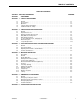
TABLE OF CONTENTS TABLE OF CONTENTS SUBJECT - SECTION, PARAGRAPH SECTION PAGE NO. - FOREWORD SECTION 1 - SAFETY PRECAUTIONS 1.1 1.2 1.3 1.4 1.5 General . . . . . . . . . . . . . . . . . . . . . . . . . . . . . . . . . . . . . . . . . . . . . . . . . . . . . . . . . . . . . . . . . . . . . .1-1 Pre-operation. . . . . . . . . . . . . . . . . . . . . . . . . . . . . . . . . . . . . . . . . . . . . . . . . . . . . . . . . . . . . . . . . .1-1 Operation. . . . . . . . . . . . . . . . . . . . . . . . . . . .
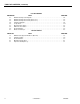
TABLE OF CONTENTS (Continued) LIST OF FIGURES FIGURE NO. 2-1. 2-2. 2-3. 2-4. 2-5. 3-1. 3-2. 3-3. 4-1. TITLE PAGE NO. Walk-Around Inspection Diagram . . . . . . . . . . . . . . . . . . . . . . . . . . . . . . . . . . . . . . . . . . . . . . . . . .2-4 Walk-Around Inspection Points (Sheet 1 of 2) . . . . . . . . . . . . . . . . . . . . . . . . . . . . . . . . . . . . . . . .2-5 Walk-Around Inspection Points (Sheet 2 of 2) . . . . . . . . . . . . . . . . . . . . . . . . . . . . . . . . . . . . . . . .
SECTION 1 - SAFETY PRECAUTIONS SECTION 1. SAFETY PRECAUTIONS 1.1 • Do not operate this machine until complete training is performed by authorized persons. GENERAL This section outlines the necessary precautions for proper and safe machine usage and maintenance. For proper machine use, it is mandatory that a daily routine is established based on the content of this manual.
SECTION 1 - SAFETY PRECAUTIONS Machine Inspection • Before machine operation, perform inspections and functional checks. Refer to Section 2 of this manual for detailed instructions. • Do not operate this machine until it has been serviced and maintained according to requirements specified in the Service and Maintenance Manual. • Be sure all safety devices are operating properly. Modification of these devices is a safety violation.
SECTION 1 - SAFETY PRECAUTIONS • Platform-to-structure transfers at elevated positions are discouraged. Where transfer is necessary, enter/exit through the gate only with the platform within 1 foot (0.3m) of a safe and secure structure. 100% tie-off is also required in this situation using two lanyards. One lanyard must be attached to the platform with the second lanyard attached to the structure.
SECTION 1 - SAFETY PRECAUTIONS • Do not raise the platform or drive from an elevated position unless the machine is on firm, level surfaces and evenly supported. • Keep the chassis of the machine at least 2 ft. (0.6m) from holes, bumps, drop-offs, obstructions, debris, concealed holes, and other potential hazards on the floor/surface unless approved by JLG.
SECTION 2 - PREPARATION AND INSPECTION SECTION 2. PREPARATION AND INSPECTION 2.1 GENERAL 2.3 DELIVERY AND PERIODIC INSPECTION This section provides the necessary information needed by those personnel that are responsible to place the machine in operation readiness, and lists checks that are performed prior to use of the machine. It is important that the information contained in this section be read and understood before any attempt is made to operate the machine.
SECTION 2 - PREPARATION AND INSPECTION Drive Hubs Control Boxes. (Console and Ground) Check oil level in drive hub by removing pipe plug and feeling for oil level. (Contact service personnel for assistance if needed.) Switches operable; no visible damage; placards secure and legible. Hand controller operable; no visible damage. NOTE: Torque Hubs should be one-half full of lubricant.
SECTION 2 - PREPARATION AND INSPECTION 2.4 Machine Log DAILY WALK-AROUND INSPECTION It is the users responsibility to inspect the machine before the start of each workday. It is recommended that each user inspect the machine before operation, even if the machine has already been put into service under another user. This Daily Walk-Around Inspection is the preferred method of inspection.
SECTION 2 - PREPARATION AND INSPECTION Figure 2-1.
SECTION 2 - PREPARATION AND INSPECTION GENERAL Begin the “Walk-Around Inspection” at Item 1, as noted on the diagram.Continue to the right (counterclockwise viewed from top) checking each item in sequence for the conditions listed in the “Walk-Around Inspection Checklist”. 11. Hydraulic Filter - No visible damage, properly secured, no evidence of leakage. 12. Control Valves - Valves properly secured, no visible damage, no evidence of leakage.
SECTION 2 - PREPARATION AND INSPECTION 28. Drive Motor, Right Rear - No visible damage, no evidence of leakage. 29. Drive Brake, Right Rear - No loose or missing parts, no visible damage, no evidence of leakage. 30. Drive Hub, Right Rear - No visible damage, no evidence of leakage. Drive hubs should be one half full of EPGL SAE 90. 31. Drive Wheel and Tire Assembly, Left Rear - Properly secured no loose or missing lug nuts, no visible damage. Refer to inflation psi stenciled on frame or wheel rims. 32.
SECTION 2 - PREPARATION AND INSPECTION 2.5 DAILY FUNCTIONAL CHECK 2.6 TO AVOID SERIOUS INJURY, DO NOT OPERATE MACHINE IF ANY CONTROL LEVERS OR TOGGLE SWITCHES CONTROLLING PLATFORM MOVEMENT DO NOT RETURN TO THE OFF POSITION WHEN RELEASED. A functional check of all systems should be performed, under no load, once the walk-around inspection is complete, in an area free of overhead and ground level obstructions. Perform pre-load functional check in accordance with the following procedure: 1.
Figure 2-4.
SECTION 2 - PREPARATION AND INSPECTION Table 2-1.
SECTION 2 - PREPARATION AND INSPECTION 2.7 4. As the engine begins to stumble place the switch to the LPG position, allowing the LP fuel to be sent to the fuel regulator. DUAL FUEL SYSTEM IT IS POSSIBLE TO SWITCH FROM ONE FUEL SOURCE TO THE OTHER WITHOUT ALLOWING THE ENGINE TO STOP. EXTREME CARE MUST BE TAKEN AND THE FOLLOWING INSTRUCTIONS MUST BE FOLLOWED. Changing from Gasoline to LP Gas 1. Start the engine from the ground control station. 2.
Figure 2-5.
SECTION 2 - PREPARATION AND INSPECTION This page intentionally left blank.
SECTION 3 - USER RESPONSIBILITIES AND MACHINE CONTROL SECTION 3. USER RESPONSIBILITIES AND MACHINE CONTROL 3.1 6. The safest means to operate near overhead obstructions, other moving equipment, obstacles, depressions, holes, dropoffs, etc. on the supporting surface. GENERAL SINCE THE MANUFACTURER HAS NO DIRECT CONTROL OVER MACHINE APPLICATION AND OPERATION, CONFORMANCE WITH GOOD SAFETY PRACTICES IN THESE AREAS IS THE RESPONSIBILITY OF THE USER AND HIS OPERATING PERSONNEL.
SECTION 3 - USER RESPONSIBILITIES AND MACHINE CONTROL Capacities Raising platform above horizontal with or without any load in platform, is based on the following criteria: 1. Machine is positioned on a smooth, firm and level surface. 2. Load is within manufacturer’s rated capacity. 2. Platform/Ground Select Switch - A three position Platform/Ground Select switch supplies operating power to the platform or ground controls, as selected.
SECTION 3 - USER RESPONSIBILITIES AND MACHINE CONTROL Figure 3-1. Ground Control Station 6. Choke Switch - (If Equipped) - A momentary contact, push-button type switch supplies power to the choke solenoid, when depressed, to assist cold start operation. 7. Gasoline/LPG Select Switch - (Dual Fuel Only) A three position toggle-type switch is used to select the desired method of powering the unit.
SECTION 3 - USER RESPONSIBILITIES AND MACHINE CONTROL Figure 3-2. Platform Control Station Platform Control Station 1. Enable Switch -These machines are equipped with an enable switch on the side of the platform control console. On machines built with a serial number before 0200058922, the enable switch must be pressed before activating the drive, lift or steer functions. A built-in timer shuts off power to these functions if they are not activated within 3 seconds after the enable switch is depressed.
SECTION 3 - USER RESPONSIBILITIES AND MACHINE CONTROL IF TILT ALARM IS ON WHEN PLATFORM IS RAISED, LOWER PLATFORM COMPLETELY, THEN REPOSITION MACHINE SO THAT IT IS LEVEL BEFORE RAISING PLATFORM. 5. Tilt Alarm Warning Light - A warning light on the control console that lights when the chassis is on a severe slope (over 3 °). NOTE: The lift toggle switch automatically returns to the center off position when released.
SECTION 3 - USER RESPONSIBILITIES AND MACHINE CONTROL Figure 3-3.
SECTION 3 - USER RESPONSIBILITIES AND MACHINE CONTROL 0253661 0271148 1 2 3 4 5 6 7 8 9 10 11 12 13 14 15 16 1701832 1701871 4420039 1701871 0860520 1060279 Use 1703788 1703788 0641405 4751400 4761400 3311405 1701843 1701837 Not Available Use 1703814 1703814 1703811 4420067 0257583 0257584 0257585 0253667 0253674 0253681 0253663 0253670 0253677 0253664 0253671 0253745 0253665 0253672 0253679 0253666 0253673 0253680 0253668 3120825 Table 3-1.
SECTION 3 - USER RESPONSIBILITIES AND MACHINE CONTROL 0253675 0253682 26 27 28 29 30 31 32 33 34 35 36 1701885 1701886 1701887 Not Used Not Required 1703158 Not Required Not Used 1701839 1701615 1701839 1701512 1701519 1701524 1701856 Not Available 3820001 3252548 3252549 3252550 3252551 3252552 3252553 3340564 Not Used Use 3252609 3252609 3252230 37 1701523 1701617 1701523 1701511 1701516 1701520 1701860 38 1701840 1701616 1701840 3-8 Table 3-1.
SECTION 3 - USER RESPONSIBILITIES AND MACHINE CONTROL 39 40 41 42 43 44 1701515 1701525 1701535 1701858 1701504 Not Required 1703665 Not Required 1701510 3820019 Not Used Not Required 1703663 Not Required 45 Not Required 1703662 Not Required 46 Not Required 1703921 Not Required Table 3-1.
SECTION 3 - USER RESPONSIBILITIES AND MACHINE CONTROL This page left blank intentionally.
SECTION 4 - MACHINE OPERATION SECTION 4. MACHINE OPERATION 4.1 DESCRIPTION This machine is a self-propelled elevating ‘sizzor’ aerial work platform. The Sizzor Lift’s intended purpose is to position personnel with their tools and supplies at positions above ground level. The machine can be used to reach work areas located above machinery or equipment. The JLG Sizzor Lift has a primary operator Control Station in the platform.
SECTION 4 - MACHINE OPERATION 4.3 ENGINE OPERATION RTS SERIES SCISSOR LIFTS MANUFACTURED AFTER AUGUST 26, 1996 ARE EQUIPPED WITH A HYDRAULIC OIL TEMPERATURE SWITCH THAT SHUTS DOWN THE ENGINE WHEN THE HYDRAULIC OIL REACHES A TEMPERATURE OF APPROXIMATELY 111 DEGREES C (230 DEGREES F). THIS SHUT DOWN IS INTENDED TO PROTECT THE HYDRAULIC SYSTEM AND ITS COMPONENTS FROM DAMAGE DUE TO EXCESSIVE HEAT.
SECTION 4 - MACHINE OPERATION Figure 4-1. Grade and Sideslope 4.5 LEVELING JACKS (OPTIONAL) NOTE: The machine may be equipped with leveling jacks enabling the operator to level the machine on uneven surfaces. Lower leveling jacks until the bubble level located on the platform of the machine reads level. The tilt warning light and the tilt warning alarm must not be on. When using leveling jacks, always deploy all four.
SECTION 4 - MACHINE OPERATION 4.7 Traveling Forward STEERING To steer the machine, the thumb operated steer control switch on the controller handle is positioned to the right for traveling right, or to the left for traveling left. When released, the switch will return to the center-off position and the wheels will remain in the previously selected position. To return the wheels to the straightened position, the switch must be activated in the opposite direction until the wheels are centered. 4.
SECTION 4 - MACHINE OPERATION 4.9 PARKING AND STOWING 4.11 SAFETY PROPS Park and stow machine as follows: 1. Drive machine to a reasonably well-protected and well-ventilated area. SAFETY PROPS MUST BE USED WHEN MAINTENANCE PERFORMED ON MACHINE REQUIRES SIZZOR ARMS TO BE RAISED. 2. Ensure platform is fully lowered. 3. Position EMERGENCY STOP switch to OFF position. 4. If necessary, cover the instruction placards, caution and warning decals so that they will be protected from hostile environment. 5.
SECTION 4 - MACHINE OPERATION This page intentionally left blank.
SECTION 5 - EMERGENCY PROCEDURES SECTION 5. EMERGENCY PROCEDURES 5.1 GENERAL This section provides information on the procedures to be followed and on the systems and controls to be used in the event an emergency situation is encountered during machine operation. Prior to operation of the machine and periodically thereafter, the entire operating manual, including this section, should be reviewed by all personnel whose responsibilities include any work or contact with the machine. 5.
SECTION 5 - EMERGENCY PROCEDURES 5.4 Platform Caught Overhead EMERGENCY OPERATION Use of Ground Controls KNOW HOW TO USE THE GROUND CONTROLS IN AN EMERGENCY SITUATION. Ground personnel must be thoroughly familiar with the machine operating characteristics and the ground control functions. Training should include operation of the machine, review and understanding of this section and hands-on operation of the controls in simulated emergencies.
SECTION 6 - INSPECTION AND REPAIR LOG SECTION 6. INSPECTION AND REPAIR LOG Table 6-1.
SECTION 6 - INSPECTION AND REPAIR LOG Table 6-1.
JLG Industries, Inc. TRANSFER OF OWNERSHIP To: JLG, Gradall, Lull and Sky Trak product owner: If you now own, but ARE NOT the original purchaser of the product covered by this manual, we would like to know who you are. For the purpose of receiving safety-related bulletins, it is very important to keep JLG Industries, Inc. updated with the current ownership of all JLG products. JLG maintains owner information for each JLG product and uses this information in cases where owner notification is necessary.
Corporate Office JLG Industries, Inc. 1 JLG Drive McConnellsburg PA. 17233-9533 USA Phone: (717) 485-5161 Customer Support Toll Free: (877) 554-5438 Fax: (717) 485-6417 JLG Worldwide Locations JLG Industries (Australia) P.O. Box 5119 11 Bolwarra Road Port Macquarie N.S.W.