SERVICE & MAINTENANCE Model 20EL 25EL 30EL 36EL 41EL 3120782 October 31, 2003 CORPORATE OFFICE JLG INDUSTRIES, INC. 1 JLG Drive McConnellsburg, PA.
CALIFORNIAN PROPOSITION 65 BATTERY WARNING Battery posts, terminals and related accessories contain lead and lead compounds, chemical known to the State of Califormia to cause cancer and reproductive harm. bATTERY WASH HANDS AFTER HANDLING! JLG Industries (Australia) P.O. Box 5119 11 Bolwarra Road Port Macquarie N.S.W.
FOREWORD The purpose of this manual is to provide users with the operating procedures essential for the promotion of proper machine operation for its intended purpose. It is important to over-stress proper machine usage. All information in this manual should be READ and UNDERSTOOD before any attempt is made to operate the machine. YOUR OPERATING MANUAL IS YOUR MOST IMPORTANT TOOL - Keep it with the machine. REMEMBER ANY EQUIPMENT IS ONLY AS SAFE AS THE OPERATOR.
This page left intentionally blank.
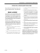
INTRODUCTION - OPERATION/SAFETY PRECAUTIONS INTRODUCTION - OPERATION/SAFETY PRECAUTIONS All procedures herein are based on the use of the machine under proper operating conditions, with no deviations from original design intent ... as per OSHA regulations. 5. Load limits specified by the manufacturer shall not be exceeded. 6. Instruction and warning placards must be legible. 7.
INTRODUCTION - MAINTENANCE SAFETY PRECAUTIONS INTRODUCTION - MAINTENANCE SAFETY PRECAUTIONS A. GENERAL C. MAINTENANCE This section contains the general safety precautions which must be observed during maintenance of the aerial platform. It is of utmost importance that maintenance personnel pay strict attention to these warnings and precautions to avoid possible injury to themselves or others or damage to the equipment.
EFFECTIVITY PAGE EFFECTIVITY CHANGES June 15, 1999 - Original Issue of Manual November 21, 2000 - Revised - Pages Affected:Section 2 - Pages 2-11, 2-18 thru 2-21.
EFFECTIVITY PAGE This Page Left Intentionally Blank d – JLG Lift – 3120782
TABLE OF CONTENTS TABLE OF CONTENTS SECTION - PARAGRAPH, SUBJECT PAGE NO. INTRODUCTION -- OPERATION/SAFETY PRECAUTIONS . . . . . . . . . . . . . . . . . . . . . . . . . . . . . . . . . . . . A INTRODUCTION -- MAINTENANCE SAFETY PRECAUTIONS. . . . . . . . . . . . . . . . . . . . . . . . . . . . . . . . . . A A GENERAL . . . . . . . . . . . . . . . . . . . . . . . . . . . . . . . . . . . . . . . . . . . . . . . . . . . . . . . . . . . . . . . . . . . . . . B B HYDRAULIC SYSTEM SAFETY . . . . . . . . . .
TABLE OF CONTENTS (Continued) Bearings. . . . . . . . . . . . . . . . . . . . . . . . . . . . . . . . . . . . . . . . . . . . . . . . . . . . . . . . . . . . . . . . . . 2-5 Gaskets . . . . . . . . . . . . . . . . . . . . . . . . . . . . . . . . . . . . . . . . . . . . . . . . . . . . . . . . . . . . . . . . . . 2-5 Bolt Usage and Torque Application . . . . . . . . . . . . . . . . . . . . . . . . . . . . . . . . . . . . . . . . . . . . 2-6 Hydraulic Lines and Electrical Wiring . . . . . . . . . . . . . . .
TABLE OF CONTENTS SECTION 3 - TROUBLESHOOTING 3.1 GENERAL . . . . . . . . . . . . . . . . . . . . . . . . . . . . . . . . . . . . . . . . . . . . . . . . . . . . . . . . . . . . . . . . . . . . .3-1 3.2 TROUBLESHOOTING INFORMATION. . . . . . . . . . . . . . . . . . . . . . . . . . . . . . . . . . . . . . . . . . . . . . .3-1 3.3 HYDRAULIC CIRCUIT CHECKS. . . . . . . . . . . . . . . . . . . . . . . . . . . . . . . . . . . . . . . . . . . . . . . . . . . .3-1 3.4 OUTRIGGER INTERLOCK CONTACTS . . . . . . . .
TABLE OF CONTENTS (Continued) This page intentionally left blank.
SECTION 1 - SPECIFICATIONS SECTION 1. SPECIFICATIONS 1.1 CAPACITIES 1.3 Hydraulic Oil Reservoir PERFORMANCE DATA Platform Capacity AC Models – 5 qts. U.S. (4.7 ltr.) PLATFORM CAPACITY DC Models – 5 qts. U.S. (4.7 ltr.) 1.2 COMPONENT DATA Hydraulic Pump/Electric Motor Assembly DC Models - 12 Volt DC motor/pump Motor - 12v - DC Standard Duty Pump Displacement – .049 cu. in./rev.(AFC 0.8 cc/rev.) Pump Output – 0.43 GPM @ 3500 PSI @ 11.
SECTION 1 - SPECIFICATIONS Maximum Working Height (Average person) 1.5 LUBRICATION 20EL-AC & DC - 26 ft. (7.92 m) Hydraulic Oil 25EL-AC & DC - 31 ft. (9.45 m) 30EL-AC & DC - 36 ft. (11 m) 36EL-AC & DC - 42 ft. (12.80 m) 41EL-AC & DC - 47 ft. (14.33 m) Platform Cycle Performance Lift Up cycle time - from stowed to maximum platform height with maximum rated load. Lift Down cycle time - from maximum platform height to stowed position with maximum rated load.
SECTION 1 - SPECIFICATIONS 1.6 HYDRAULIC PRESSURE ADJUSTMENT (See Figure 1-1.) Adjust system pressure so that platform will raise with rated capacity in platform. 1.7 NOTE: All dimensions are given in inches (in), with the metric equivalent, centimeters (cm), given in parentheses. Turning adjustment screw clockwise, increases system pressure, turning screw counterclockwise, decreases system pressure. Table 1-3. Cylinder Specifications PRESSURE ADJUSTMENT SCREW (SHOWN REMOVED) 1.
SECTION 1 - SPECIFICATIONS Figure 1-2. Torque Chart.
SECTION 1 - SPECIFICATIONS 4 1 3 2 Figure 1-3. Lubrication Locations (See Table below). Table 1-4. Lubrication Intervals for Various Components INTERVAL HOURS ITEM 1 COMPONTENT Hydraulic Oil NO/TYPE LUBE POINTS Fill To Line on Reservoir 5 Qt. (4.3 L) Reservoir LUBE/METHOD 3 MONTHS 150 Hrs. 6 MONTHS 300 Hrs. HO - Check Hyd. Oil Level HO - Change Hyd. Oil 1 YEAR 600 Hrs. 2 YEARS 1200 Hrs.
SECTION 1 - SPECIFICATIONS This page left intentionally blank 1-6 – JLG Lift – 3120782
SECTION 2 - SERVICE PROCEDURES SECTION 2. SERVICE PROCEDURES 2.1 MACHINE PREPARATION, INSPECTION, AND MAINTENANCE General This section provides the necessary information needed by those personnel that are responsible to place the machine in operation readiness and maintain its safe operating condition. For maximum service life and safe operation, ensure that all the necessary inspections and maintenance have been completed before placing the machine into service.
SECTION 2 - SERVICE PROCEDURES Table 2-1. Inspection and Maintenance Type Frequency Primary Responsibility Service Qualification Reference Pre-Start Inspection Prior to use each day; or At each Operator change. User or Operator User or Operator Pre-Delivery Inspection Prior to each sale, lease, or rental delivery. Owner, Dealer, or User Qualified JLG Mechanic Service and Maintenance Manual and applicable JLG inspection form.
SECTION 2 - SERVICE PROCEDURES Table 2-2. EL Model - Preventive Maintenance & Inspection Schedule.
SECTION 2 - SERVICE PROCEDURES Table 2-2. EL Model - Preventive Maintenance & Inspection Schedule.
SECTION 2 - SERVICE PROCEDURES 2.3 Components Removal and Installation SERVICING AND MAINTENANCE GUIDELINES Use adjustable lifting devices, whenever possible, if mechanical assistance is required. All slings (chains, cables, etc.) should be parallel to each other and as near perpendicular as possible to top of part being lifted. General The following information is provided to assist you in the use and application of servicing and maintenance procedures contained in this chapter.
SECTION 2 - SERVICE PROCEDURES Bolt Usage and Torque Application Mast Chain Inspection Procedure Use bolts of proper length. A bolt which is too long will bottom before the head is tight against its related part. If a bolt is too short, there will not be enough thread area to engage and hold the part properly. When replacing bolts, use only those having the same specifications of the original, or one which is equivalent.
SECTION 2 - SERVICE PROCEDURES Tight Joints: All joints in the leaf chain should flex freely. On leaf chain, tight joints are usually caused by rust/corrosion, or the inside plates “walking” off the bushing. Limber up rusty/corroded chains (after inspecting care fully) with a heavy application of oil (preferably a hot oil dip). Tap inside “walking” plates inward; if “walking” persists, replace the chain.
SECTION 2 - SERVICE PROCEDURES 2.4 Changing Hydraulic Oil LUBRICATION INFORMATION Hydraulic System The primary enemy of a hydraulic system is contamination. Contaminants enter the system by various means, e.g., using inadequate hydraulic oil, allowing moisture, grease, filings, sealing components, sand, etc., to enter when performing maintenance, or by permitting the pump to cavitate due to insufficient system warm-up or leaks in the pump supply.
SECTION 2 - SERVICE PROCEDURES 2.5 BATTERY CHARGER - ASSEMBLY AND DISASSEMBLY Cover Removal 5. Remove the ten (10) screws on the sides and top of the charger cover and remove cover. General Information DO NOT ATTEMPT TO DISASSEMBLE THE BATTERY CHARGER IF MACHINE IS STILL UNDER WARRANTY. OPENING THE BATTERY CHARGER WHILE THE MACHINE IS UNDER WARRANTY WILL VOID THE CHARGER WARRANTY. IF UNDER WARRANTY REQUEST A REPLACEMENT CHARGER FROM THE FACTORY.
SECTION 2 - SERVICE PROCEDURES Printed Circuit Board Replacement 1. Disconnect the wide wiring connector from the end of the circuit board. AC Circuit Breaker and Voltage Selection Switch Replacement 2. Remove the four (4) screw attaching the card to the front face of the charger chassis. 3. Remove the circuit board. 1. Remove the wiring from the AC breaker or Voltage Selection Switch terminals. 2.
SECTION 2 - SERVICE PROCEDURES Varistor Replacement (Item #3) Shunt Assembly, Varistor, and SCR Rectifier Replacement (See Illustration) 1. Remove the fasteners securing the varistor to the aluminum angle bracket (see illustration below). One through the rear panel of the base with a short white spacer and one at the long white insulator attaching the shunt assembly to the bracket. Shunt Assembly (Item #1) 1. Carefully remove the screw from the end of the shunt assembly.
SECTION 2 - SERVICE PROCEDURES 2.6 HYDRAULIC LIFT CYLINDER REMOVAL, INSPECTION AND REBUILD HYDRAULIC CYLINDERS ARE DESIGNED TO HOLD HYDRAULIC FLUID UNDER HIGH PRESSURE. BE SURE ALL APPROPRIATE MEASURES ARE TAKEN TO RELIEVE RESIDUAL PRESSURE IN THE CYLINDER BEFORE DISCONNECTING LINES. Disassembly 1. Disconnect power source. (Remove the DC power pack/charger assembly from back of mast, if so equipped). 2. Remove ground control (pump) cover.
SECTION 2 - SERVICE PROCEDURES Cylinder Assembly cates uneven loading and when this occurs, the diameter should be checked for out-of-roundness. If out-of-roundness exceeds 0.007", this is unacceptable. Check the condition of the dynamic seals and bearings looking particularly for metallic particles embedded in the bearing and in the piston seal surface. Remove the seals and bearings. Damage to the seal grooves, particularly on the sealing surfaces, is unacceptable.
SECTION 2 - SERVICE PROCEDURES 6. When the rod assembly is ready to be installed into the tube, liberally apply an anti-seize lubricant to the head outer surface, especially the static seal. 6. Install the cylinder mount at the bottom of the mast using the four (4) 1/2" bolts. Re-shim to eliminate any side clearance to prevent any strain on the sides of the mast when the bolts are tightened. 7. Next dip the entire rod assembly into hydraulic fluid and stuff this assembly into the tube.
SECTION 2 - SERVICE PROCEDURES 2.7 MAST ASSEMBLY AND DISASSEMBLY PROCEDURES The EL Series personnel lift mast sections are contructed of extruded aluminum, protected with an anodized surface finish. The mast sections rails are interlocked into each other when assembled and are guided by slide pads mounted at the top and bottom of the rails on both sides of the mast section.
SECTION 2 - SERVICE PROCEDURES Platform Section Removal (All Masts) end of mast section-6. Push threaded ends of cable through anchor plate. 3. Remove cable adjust nuts from threaded ends of cable attached to the cable anchor plate on BOTTOM end of mast section-5/-6/-7 (short, platform mounting section). Push threaded ends of cable through anchor plate 4. At TOP of mast section-5/-6/-7, pull cables out and allow to hang loose.
SECTION 2 - SERVICE PROCEDURES 22. Carefully slide mast section-4 out BOTTOM of section-3. Remove slide pads, shims and chain anchor plate, if necessary. NOTE: When sliding mast sections apart, be careful not to scratch or score the anodized finish in the slide pad channels. 34. Carefully slide mast section-2 out BOTTOM of section-1. Remove slide pads and shims, if necessary. Mast Section 3 Removal (All Masts) 23.
SECTION 2 - SERVICE PROCEDURES 2.8 c. Check mast section for side play. If play exists add .015" shims dividing the thickness equally between both sides of mast. Insert shims until the shims cannot be inserted halfway by hand with the mast pulled to the opposite side. MAST ASSEMBLY (See Figure 2-3., Figure 2-4. or Figure 2-5.) Mast Section 1 - Assembly (All Masts) d. When mast slide pads are shimmed properly, there should be no side to side movement of slide pad in rail channel.
SECTION 2 - SERVICE PROCEDURES UPPER SEQUENCE CABLE ASSEMBLY MAST SECTION-4 MAST SECTION-1 MAST SECTION-3 MAST SECTION-5 MAST SECTION-2 SECTION-5 UPPER SLIDE PAD MOUNTING POSITION PRIOR TO C# 142920 SECTION-5 UPPER SLIDE PAD AS OF C# 142920 LOWER SEQUENCE CABLE ASSEMBLY Figure 2-3. 20EL Mast Assembly Components.
SECTION 2 - SERVICE PROCEDURES UPPER SEQUENCE CABLE ASSEMBLY MAST SECTION-1 MAST SECTION-5 MAST SECTION-2 MAST SECTION-3 MAST SECTION-4 MAST SECTION-6 SECTION-6 UPPER SLIDE PAD MOUNTING POSITION PRIOR TO C# 142920 LOWER SEQUENCE CABLE ASSEMBLY SECTION-6 UPPER SLIDE PAD AS OF C# 142920 Figure 2-4. 25EL & 36EL Mast Assembly Components.
SECTION 2 - SERVICE PROCEDURES UPPER SEQUENCE CABLE ASSEMBLY MAST SECTION-1 MAST SECTION-2 MAST SECTION-6 MAST SECTION-3 MAST SECTION-4 MAST SECTION-5 MAST SECTION-7 IMPORTANT UPPER SLIDE PAD MOUNTING POSITION PRIOR TO C# 142920 41AM 30AM LOWER SEQUENCE CABLE ASSEMBLY SECTION-7 UPPER SLIDE PAD AS OF C# 142920 Figure 2-5. 30EL & 41EL Mast Assembly Components.
SECTION 2 - SERVICE PROCEDURES MAST SECTIONS SECTION 5 SECTION 4 SECTION 3 SECTION 2 SECTION 1 HYD. CYL. LIFTS HERE CHAIN ASSY. CABLE ASSY. CHAIN ASSY. CHAIN / CABLE ASSY. ANCHOR PLATES Figure 2-6. Mast Chain/Cable Routing Diagram.
SECTION 2 - SERVICE PROCEDURES a. Insert sheave pin through anchor block on cylinder rod end. c. Place two (2) sheave pin attach bars, one each end of sheave pin to outside of space tubes. b. Place sheave wheels (for wide chain) on sheave pin, one each side of anchor block. d. Holding complete sheave wheel assembly, slide assembly into top of mast section-3 and align threaded holes in sheave pin attach bars with holes in mast rails. c.
SECTION 2 - SERVICE PROCEDURES 30. Locate mast section-4, carefully slide section-4 closed rail into section-3 open rail. Slide sections together until ends are even. NOTE: When sliding mast sections together, be careful not to scratch or score the anodized finish in the slide pad channels. 31. Locate one (1) of the chain/cable anchor plates (one with two threaded holes vertically aligned in center of bracket).
SECTION 2 - SERVICE PROCEDURES x 3/4" long bolts, place a flatwasher under head of each bolt. 45. Slide mast section-5 out the top of mast section-4 so the chain/cable anchor plate on bottom of mast section-5 is easily accessible near top end of mast section-4. Rest the top end of mast section-5 on a support while performing next step. 46. Insert threaded ends of cable assembly (attached to top of mast section-3) through the chain/cable anchor plate located on bottom of extended mast section-5.
SECTION 2 - SERVICE PROCEDURES 60. Insert threaded ends of cable assembly (attached to top of mast section-4) through the chain/cable anchor plate located on bottom of extended mast section-6. Loosely thread two (2) 3/8"-16UNC nuts onto stud threads on each chain. Chains will be adjusted later in assembly. 61. Slide mast section-6 back into section-5 except for a foot or two of length. 62. While mast section-6 is still extended from section-5, assemble cable sheaves to top of mast section-6 as follows; a.
SECTION 2 - SERVICE PROCEDURES shim stock and slide pad to mast section rail with shim stock against rail and slide pad with beveled side out). PRIOR TO C# 142920 THE EL MAST INSTALLED TWO SHORT SLIDE PADS ON EACH SIDE OF THE PLATFORM MOUNTING MAST SECTION. AS OF C# 142920 A LONGER SINGLE PAD IS INSTALLED ON EACH SIDE. ON MACHINES PRIOR TO C# 142920 THE 41EL MOUNTS THE (SHORT) UPPER SLIDE PAD IN THE UPPER SET OF SLIDE PAD MOUNTING HOLES.
SECTION 2 - SERVICE PROCEDURES 2.9 8. Locate the two (2) mast support braces, attach to sides of base frame using a 3/8"-16UNC x 1" long hex head bolt, nut and flatwashers each brace, (place a flatwasher under bolt head and nut and mount with nuts on inside of frame. Use access hole in bottom of frame to attach nut inside frame). MAST TO BASE FRAME INSTALLATION 1.
SECTION 2 - SERVICE PROCEDURES Adjust using the following procedure; 2.10 MAST CHAINS/CABLES AND SEQUENCING CABLES ADJUSTMENT Mast Chain/Cable Adjustment The intention of this procedure is to assure equal load distribution between the individual chains/cables of a mast section chain/cable set. Also to step each front mast section up approximately 1/4 in. (6.5mm) from the section behind it to allow clearance for the individual mast section covers. 1.
SECTION 2 - SERVICE PROCEDURES NOTE: Mast section-1 is fixed to the base and mast section2 is attached to the lift cylinder, these sections require no adjustment. 3. Adjust one mast section at a time starting from the back (section-3, section-4, etc.) of the mast and work forward. (i.e.. if three is OK, then jump to four, etc.) 4. To adjust, elevate the platform until the chain/cable anchor adjust nuts are accessible at the front and bottom of each mast section. 2.
SECTION 2 - SERVICE PROCEDURES Clamp Installation (Drum/Socket Type) 3. Use a suitable tool and cut the cable as shown in the illustration following. For 1/8 in. cable the recommended length is 5/8 in. past the end of the sleeve. THE MANUFACTURER OF THE DRUM/SOCKET CLAMP RECOMMENDS THE USE OF THEIR CABLE CLAMP ASSEMBLY KIT (JLG P/N - 7023275) TO ASSEMBLE THE CLAMP TO THE WIRE ROPE.
SECTION 2 - SERVICE PROCEDURES 6. Reclamp the assembly in the vise on the flats of the sleeve. Using the plug driver, a metal tube or pliers, bend the outer strands toward the center strands enough that the socket can be slipped over all the strands. 8. Inspect for proper assembly prior to loading the cable. Strands visible through the inspection hole are your assurance of a proper assembly.
SECTION 3 - TROUBLESHOOTING SECTION 3. TROUBLESHOOTING 3.1 GENERAL 3.3 This section contains troubleshooting information to be used for locating and correcting most of the operating problems which may develop in the aerial platform. If a problem should develop which is not presented in this section or which is not corrected by listed corrective actions, technically qualified guidance should be obtained before proceeding with any maintenance. 3.
SECTION 3 - TROUBLESHOOTING Table 3-1. AC Unit - Troubleshooting TROUBLE PROBABLE CAUSE REMEDY Outriggers are not properly inserted in outrigger sockets. Check all outriggers for proper installation in outrigger sockets Power source is OFF. Check power source. Fuse(s) blown. Check all insulating grommets on inter-lock contactors in base frame outrigger sockets and contactor plates on outrigger beams. Replace damaged grommet(s) and replace blown fuse.
SECTION 3 - TROUBLESHOOTING Table 3-2. DC Unit - Troubleshooting TROUBLE PROBABLE CAUSE REMEDY Outriggers are not properly inserted in outrigger sockets. Check all outriggers for proper installation in outrigger sockets Power source is OFF. Check power source. Fuse(s) blown. Check all insulating grommets on inter-lock contactors in base frame outrigger sockets and contactor plates on outrigger beams. Replace damaged grommet(s) and replace blown fuse.
SECTION 3 - TROUBLESHOOTING 3.4 4. Apply Loctite #242 to screw threads. OUTRIGGER INTERLOCK CONTACTS 5. Install one (1) standard #8 brass nut and thread in against nylon washer until insulating grommet just starts to compress. Outrigger Socket and Outrigger Beam Interlock Contacts It is very important that the outrigger interlock contacts located on the bottom surface inside the outrigger sockets of the base frame, and the contactor plate on the bottom of each outrigger beam are installed correctly.
SECTION 3 - TROUBLESHOOTING ORIGINAL DESIGN BRASS COUNTERSUNK FLAT HEAD SCREW TYPICAL SAFETY DETENT (BUTTON HEAD SCREW) ARRANGEMENT ON AM MODELS (SEE SUB-SECTION BELOW - "SAFETY DETENT SCREWS") OUTRIGGER BEAM ASSEMBLY BRASS LOCKNUT (USE TO ADJUST PLATE HEIGHT WHEN TIGHTENING) NYLON WASHER INSULATING GROMMET NYLON WASHERS 0.175" OUTRIGGER BEAM CONTACTOR PLATE PLATE HEIGHT ADJUSTMENT O/R SOCKET CONTACTOR SCREW HEAD CONTACTOR SCREW 0.212" HEIGHT ADJ.
SECTION 3 - TROUBLESHOOTING 5. On the inside of the outrigger beam, install two nylon washers on the screw with the two (2) o-rings installed (one towards jack end) and three (3) nylon washers on the the other screw (towards open end of beam). 6. Coat the threads of the screws with Loctite #222 and thread the steel acorn nuts onto each screw. Hold the acorn nuts and tighten the screws using a cordless screw driver set at the #1 torque setting. Detent Screws (See Figure 3-1.
SECTION 3 - TROUBLESHOOTING 2792491_A Figure 3-2. Hydraulic Schematic.
SECTION 3 - TROUBLESHOOTING 4933203_C Figure 3-3. Electrical Diagram.
SECTION 3 - TROUBLESHOOTING 4933203_C Figure 3-3. Electrical Diagram.
SECTION 3 - TROUBLESHOOTING 4933204_H Figure 3-4. Electrical Diagram.
SECTION 3 - TROUBLESHOOTING 4933204_H Figure 3-4. Electrical Diagram.
SECTION 3 - TROUBLESHOOTING 4933205_H Figure 3-5. Electrical Diagram.
SECTION 3 - TROUBLESHOOTING 4933205_H Figure 3-5. Electrical Diagram.
SECTION 3 - TROUBLESHOOTING This page left intentionally blank.