Operation and Safety Manual Original Instructions - Keep this manual with the machine at all times.
NOTE: This manual also applies to machines with the following Serial Numbers: 0300159794, 0300159795, 0300160088, 0300160456, and E300001067.
FOREWORD FOREWORD This manual is a very important tool! Keep it with the machine at all times. The purpose of this manual is to provide owners, users, operators, lessors, and lessees with the precautions and operating procedures essential for the safe and proper machine operation for its intended purpose. Due to continuous product improvements, JLG Industries, Inc. reserves the right to make specification changes without prior notification. Contact JLG Industries, Inc. for updated information.
FOREWORD SAFETY ALERT SYMBOLS AND SAFETY SIGNAL WORDS This is the Safety Alert Symbol. It is used to alert you to the potential personal injury hazards. Obey all safety messages that follow this symbol to avoid possible injury or death INDICATES AN IMMINENTLY HAZARDOUS SITUATION. IF NOT AVOIDED, WILL RESULT IN SERIOUS INJURY OR DEATH. THIS DECAL WILL HAVE A RED BACKGROUND. INDICATES A POTENTIALLY HAZARDOUS SITUATION. IF NOT AVOIDED, COULD RESULT IN SERIOUS INJURY OR DEATH.
FOREWORD For: THIS PRODUCT MUST COMPLY WITH ALL SAFETY RELATED BULLETINS. CONTACT JLG INDUSTRIES, INC. OR THE LOCAL AUTHORIZED JLG REPRESENTATIVE FOR INFORMATION REGARDING SAFETY-RELATED BULLETINS WHICH MAY HAVE BEEN ISSUED FOR THIS PRODUCT. • Accident Reporting • Product Safety Publications • Current Owner Updates JLG INDUSTRIES, INC. SENDS SAFETY RELATED BULLETINS TO THE OWNER OF RECORD OF THIS MACHINE. CONTACT JLG INDUSTRIES, INC. TO ENSURE THAT THE CURRENT OWNER RECORDS ARE UPDATED AND ACCURATE.
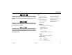
FOREWORD REVISION LOG d Original Issue - June 19, 2012 Revised - June 29, 2012 Revised - April 1, 2013 Revised - October 1, 2014 – JLG Lift – 3121289
TABLE OF CONTENTS SECTION - PARAGRAPH, SUBJECT PAGE SECTION - PARAGRAPH, SUBJECT SECTION - 1 - SAFETY PRECAUTIONS 1.1 1.2 1.3 1.4 1.5 2.2 GENERAL . . . . . . . . . . . . . . . . . . . . . . . . . . . . . . . . . . . . . . . . . . . . 1-1 PRE-OPERATION . . . . . . . . . . . . . . . . . . . . . . . . . . . . . . . . . . . . . 1-1 Operator Training and Knowledge . . . . . . . . . . . . . . . . . 1-1 Workplace Inspection. . . . . . . . . . . . . . . . . . . . . . . . . . . . . . 1-2 Machine Inspection. .
TABLE OF CONTENTS SECTION - PARAGRAPH, SUBJECT 4.5 4.6 4.7 4.8 4.9 4.10 4.11 4.12 4.13 4.14 PAGE STEERING. . . . . . . . . . . . . . . . . . . . . . . . . . . . . . . . . . . . . . . . . . . . 4-9 PLATFORM . . . . . . . . . . . . . . . . . . . . . . . . . . . . . . . . . . . . . . . . . . 4-9 Platform Level Adjustment . . . . . . . . . . . . . . . . . . . . . . . . 4-9 Platform Rotation . . . . . . . . . . . . . . . . . . . . . . . . . . . . . . . . . 4-9 BOOM . . . . . . . . . . . . . . . . . . . . .
TABLE OF CONTENTS SECTION - PARAGRAPH, SUBJECT 6.4 6.5 6.6 6.7 PAGE SECTION - PARAGRAPH, SUBJECT TIRES & WHEELS. . . . . . . . . . . . . . . . . . . . . . . . . . . . . . . . . . . . . 6-34 Tire Inflation. . . . . . . . . . . . . . . . . . . . . . . . . . . . . . . . . . . . . 6-34 Tire Damage. . . . . . . . . . . . . . . . . . . . . . . . . . . . . . . . . . . . . 6-34 Tire Replacement . . . . . . . . . . . . . . . . . . . . . . . . . . . . . . . . 6-34 Wheel and Tire Replacement. . . . . . . . . . .
TABLE OF CONTENTS SECTION - PARAGRAPH, SUBJECT PAGE Engine Operating Temperature Specifications - Caterpillar - Sheet 1 of 2 . . . . . . . . . . . . . . . . . . . . . . . . . . . . . . . . . . . . . . 6-12 6-3. Engine Operating Temperature Specifications - Caterpillar Sheet 2 of 2 . . . . . . . . . . . . . . . . . . . . . . . . . . . . . . . . . . . . . . . 6-13 6-4. Engine Operating Temperature Specifications - Deutz Sheet 1 of 2 . . . . . . . . . . . . . . . . . . . . . . . . . . . . . . . . . . . . . .
SECTION 1 - SAFETY PRECAUTIONS SECTION 1. SAFETY PRECAUTIONS 1.1 GENERAL This section outlines the necessary precautions for proper and safe machine usage and maintenance. It is mandatory that a daily routine is established based on the content of this manual to promote proper machine usage.
SECTION 1 - SAFETY PRECAUTIONS • An operator must not accept operating responsibilities until adequate training has been given by competent and authorized persons. • Allow only those authorized and qualified personnel to operate the machine who have demonstrated that they understand the safe and proper operation and maintenance of the unit. • Precautions to avoid all hazards in the work area must be taken by the user before and during operation of the machine.
SECTION 1 - SAFETY PRECAUTIONS Machine Inspection 1.3 • Do not operate this machine until the inspections and functional checks as specified in Section 2 of this manual have been performed. General • Do not operate this machine until it has been serviced and maintained according to the maintenance and inspection requirements as specified in the machine’s Service and Maintenance Manual. • Ensure all safety devices are operating properly. Modification of these devices is a safety violation.
SECTION 1 - SAFETY PRECAUTIONS • Do not carry materials directly on platform railing unless approved by JLG. • When two or more persons are in the platform, the operator shall be responsible for all machine operations. • Always ensure that power tools are properly stowed and never left hanging by their cord from the platform work area. Trip and Fall Hazards • During operation, occupants in the platform must wear a full body harness with a lanyard attached to an authorized lanyard anchorage point.
SECTION 1 - SAFETY PRECAUTIONS • Before operating the machine, make sure all gates are closed and fastened in their proper position. Electrocution Hazards • This machine is not insulated and does not provide protection from contact or proximity to electrical current. • Keep both feet firmly positioned on the platform floor at all times. Never position ladders, boxes, steps, planks, or similar items on unit to provide additional reach for any purpose.
SECTION 1 - SAFETY PRECAUTIONS Table 1-1. Minimum Approach Distances (M.A.D.) • Allow for machine movement and electrical line swaying.
SECTION 1 - SAFETY PRECAUTIONS • The minimum approach distance may be reduced if insulating barriers are installed to prevent contact, and the barriers are rated for the voltage of the line being guarded. These barriers shall not be part of (or attached to) the machine. The minimum approach distance shall be reduced to a distance within the designed working dimensions of the insulating barrier.
SECTION 1 - SAFETY PRECAUTIONS • Never exceed the maximum work load as specified on the platform. Keep all loads within the confines of the platform, unless authorized by JLG. • Do not operate the machine when wind conditions exceed 28 mph (12.5 m/s). Refer to Table 1-2, Beaufort Scale (For Reference Only). • Keep the chassis of the machine a minimum of 2 ft. (0.6m) from holes, bumps, drop-offs, obstructions, debris, concealed holes, and other potential hazards at the ground level.
SECTION 1 - SAFETY PRECAUTIONS DO NOT OPERATE THE MACHINE WHEN WIND CONDITIONS EXCEED 28 MPH (12.5 M/S). Table 1-2. Beaufort Scale (For Reference Only) 3121618 Wind Speed Beaufort Number mph m/s 0 0 0-0.2 Calm Calm. Smoke rises vertically 1 1-3 0.3-1.5 Light air Wind motion visible in smoke 2 4-7 1.6-3.3 Light breeze Wind felt on exposed skin. Leaves rustle Description Land Conditions 3 8-12 3.4-5.4 Gentle breeze Leaves and smaller twigs in constant motion 4 13-18 5.5-7.
SECTION 1 - SAFETY PRECAUTIONS • Keep non-operating personnel at least 6 ft. (1.8m) away from machine during all driving and swing operations. Crushing and Collision Hazards • Approved head gear must be worn by all operating and ground personnel. • Check work area for clearances overhead, on sides, and bottom of platform when lifting or lowering platform, and driving.
SECTION 1 - SAFETY PRECAUTIONS 1.4 TOWING, LIFTING, AND HAULING 1.5 • Never allow personnel in platform while towing, lifting, or hauling. This sub-section contains general safety precautions which must be observed during maintenance of this machine. Additional precautions to be observed during machine maintenance are inserted at the appropriate points in this manual and in the Service and Maintenance Manual.
SECTION 1 - SAFETY PRECAUTIONS • DO NOT use your hand to check for leaks. Use a piece of cardboard or paper to search for leaks. Wear gloves to help protect hands from spraying fluid. • Do not use machine as a ground for welding. • When performing welding or metal cutting operations, precautions must be taken to protect the chassis from direct exposure to weld and metal cutting spatter. • Do not refuel the machine with the engine running. • Use only approved non-flammable cleaning solvents.
SECTION 1 - SAFETY PRECAUTIONS Battery Hazards • Always disconnect batteries when servicing electrical components or when performing welding on the machine. • Do not allow smoking, open flame, or sparks near battery during charging or servicing. BATTERY FLUID IS HIGHLY CORROSIVE. AVOID CONTACT WITH SKIN AND CLOTHING AT ALL TIMES. IMMEDIATELY RINSE ANY CONTACTED AREA WITH CLEAN WATER AND SEEK MEDICAL ATTENTION. • Do not contact tools or other metal objects across the battery terminals.
SECTION 1 - SAFETY PRECAUTIONS NOTES: 1-14 – JLG Lift – 3121618
SECTION 2 - USER RESPONSIBILITIES, MACHINE PREPARATION, AND INSPECTION SECTION 2. USER RESPONSIBILITIES, MACHINE PREPARATION, AND INSPECTION 6. The safest means to operate the machine where overhead obstructions, other moving equipment, and obstacles, depressions, holes, dropoffs. 2.1 PERSONNEL TRAINING The aerial platform is a personnel handling device; so it is necessary that it be operated and maintained only by trained personnel.
SECTION 2 - USER RESPONSIBILITIES, MACHINE PREPARATION, AND INSPECTION 2.2 PREPARATION, INSPECTION, AND MAINTENANCE The following table covers the periodic machine inspections and maintenance required by JLG Industries, Inc. Consult local regulations for further requirements for aerial work platforms.
SECTION 2 - USER RESPONSIBILITIES, MACHINE PREPARATION, AND INSPECTION Table 2-1.Inspection and Maintenance Table Type Primary Responsibility Frequency Service Qualification Reference Pre-Start Inspection Before using each day; or whenever there’s an Operator change. User or Operator User or Operator Operator and Safety Manual Pre-Delivery Inspection (See Note) Before each sale, lease, or rental delivery.
SECTION 2 - USER RESPONSIBILITIES, MACHINE PREPARATION, AND INSPECTION 4. Operation and Safety Manuals – Make sure a copy of the Operator and Safety Manual, AEM Safety Manual (ANSI markets only), and ANSI Manual of Responsibilities (ANSI markets only) is enclosed in the weather resistant storage container. Pre-Start Inspection The Pre-Start Inspection should include each of the following: 1. Cleanliness – Check all surfaces for leakage (oil, fuel, or battery fluid) or foreign objects.
SECTION 2 - USER RESPONSIBILITIES, MACHINE PREPARATION, AND INSPECTION 11. Function Check – Once the “Walk-Around” Inspection is complete, perform a functional check of all systems in an area free of overhead and ground level obstructions. Refer to Section 4 for more specific instructions. 2. From the platform control console: a. Ensure that the control console is firmly secured in the proper location; b.
SECTION 2 - USER RESPONSIBILITIES, MACHINE PREPARATION, AND INSPECTION 11 12 10 4 9 13 16 8 7 3 17 14 6 18 2 15 5 1 Figure 2-1.
SECTION 2 - USER RESPONSIBILITIES, MACHINE PREPARATION, AND INSPECTION 1. 2. 3. 4. 5. 6. 7. 8. 9. 10. 11. 12. 13. 14. 15. 16. 17. 18. Front Drive/Steer Wheels Rear Drive Wheels Tower Lift Cylinder Lower Upright Main Lift Cylinder Main Boom Assembly Power Track Level Cylinder Jib Cylinder Platform Platform Console Jib Fly Boom Section Base Boom Section Master Cylinder Tower Boom Turntable Frame Figure 2-2.
SECTION 2 - USER RESPONSIBILITIES, MACHINE PREPARATION, AND INSPECTION 7 3 16 7 2 15 5 8 6 9 4 3 2 3 3 3 14 6 8 3 7 10,11 12,13 1 7 Figure 2-3.
SECTION 2 - USER RESPONSIBILITIES, MACHINE PREPARATION, AND INSPECTION GENERAL Begin the "Walk-Around Inspection" at Item 1, as noted on the diagram. Continue to the right (counterclockwise viewed from top) checking each item in sequence for the conditions listed in the following checklist. 2. Platform & Ground Control Consoles - Switches and levers return to neutral, decals/placards secure and legible, control markings legible. 3.
SECTION 2 - USER RESPONSIBILITIES, MACHINE PREPARATION, AND INSPECTION 9. Tie Rod Ends and Steering Spindles - See Inspection Note. 12. Auxiliary Hydraulic Pump - See Inspection Note. 13. Main Hydraulic Pump - See Inspection Note. 10. Turntable Bearing - Evidence of proper lubrication. No evidence of loose bolts or looseness between bearing and machine. 11. Swing Motor and Worm Gear - Evidence of proper lubrication; No evidence of damage. 14. Platform Rotator - See Inspection Note. 15.
SECTION 2 - USER RESPONSIBILITIES, MACHINE PREPARATION, AND INSPECTION 2.3 OSCILLATING AXLE LOCKOUT TEST (IF EQUIPPED) LOCKOUT SYSTEM TEST MUST BE PERFORMED QUARTERLY, ANY TIME A SYSTEM COMPONENT IS REPLACED, OR WHEN IMPROPER SYSTEM OPERATION IS SUSPECTED. NOTE: Ensure boom is fully retracted, lowered, and centered between drive wheels prior to beginning lockout cylinder test. 1. Place a 6 inches (15.2 cm) high block with ascension ramp in front of left front wheel. 2.
SECTION 2 - USER RESPONSIBILITIES, MACHINE PREPARATION, AND INSPECTION 11. Have an assistant check to see that right front or left rear wheel remains elevated in position off of ground. 12. Carefully activate Swing control lever and return boom to stowed position (centered between drive wheels). When boom reaches center, stowed position, lockout cylinders should release and allow wheel to rest on ground, it may be necessary activate Drive to release cylinders. 2-12 13.
SECTION 3 - MACHINE CONTROLS AND INDICATORS SECTION 3. MACHINE CONTROLS AND INDICATORS 3.1 GENERAL NOTE: The indicator panels use different shaped symbols to alert the operator to different types of operational situations that could arise. The meaning of those symbols are explained below. THE MANUFACTURER HAS NO DIRECT CONTROL OVER MACHINE APPLICATION AND OPERATION. THE USER AND OPERATOR ARE RESPONSIBLE FOR CONFORMING WITH GOOD SAFETY PRACTICES.
SECTION 3 - MACHINE CONTROLS AND INDICATORS TO AVOID SERIOUS INJURY, DO NOT OPERATE MACHINE IF ANY CONTROL LEVERS OR TOGGLE SWITCHES CONTROLLING PLATFORM MOVEMENT DO NOT RETURN TO THE OFF POSITION WHEN RELEASED. ONLY USE THE PLATFORM LEVELING FUNCTION FOR SLIGHT LEVELING OF THE PLATFORM. INCORRECT USE COULD CAUSE THE LOAD/OCCUPANTS TO SHIFT OR FALL. FAILURE TO DO SO COULD RESULT IN DEATH OR SERIOUS INJURY. 2.
SECTION 3 - MACHINE CONTROLS AND INDICATORS 1 12 1. 2. 3. 4. 5. 6. 7. 8. 9. 10. 11. 12. Platform Rotate Platform Leveling Not Used Engine Start/Auxiliary Power/Function Enable Power/Emergency Stop Platform/Ground Select Hourmeter Swing Tower Boom Lift Main Boom Lift Telescope Indicator Panel 2 11 10 4 9 5 6 QUARTZ 1 10 HOURS 8 7 Figure 3-1.
SECTION 3 - MACHINE CONTROLS AND INDICATORS 1 1. 2. 3. 4. 5. 6. 7. 8. 9. 10. 11. 12. Platform Rotate Platform Leveling Jib Lift Engine Start/Auxiliary Power/Function Enable Power/Emergency Stop Platform/Ground Select Hourmeter Swing Tower Boom Lift Main Boom Lift Telescope Indicator Panel 12 2 11 3 10 4 9 5 6 QUARTZ 1 10 HOURS 8 7 Figure 3-1.
SECTION 3 - MACHINE CONTROLS AND INDICATORS 4. Engine Start/ Auxiliary Power Switch /Function Enable NOTE: To start the engine, the switch must be held "UP" until the engine starts. To use auxiliary power, the switch must be held “DOWN” for duration of auxiliary pump use. Aux power can only be used if the engine is not running. When the Platform/Ground Select Switch is in the center position, power is shut off to the controls at both operating stations.
SECTION 3 - MACHINE CONTROLS AND INDICATORS 9. Tower Boom Lift Ground Control Indicator Panel Provides raising and lowering of the Lower and Mid Booms. 1. Battery Charging Indicator Indicates a problem in the battery or charging circuit, and service is required. 10. Main Boom Lift 2. Engine Oil Pressure Indicator Provides raising and lowering of the Main Boom. Indicates that engine oil pressure is below normal and service is required. 3.
SECTION 3 - MACHINE CONTROLS AND INDICATORS 9 1. 2. 3. 4. 5. Battery Charging Low Engine Oil Pressure High Engine Coolant Temp. Engine Oil Temp. System Distress 6. 7. Low Fuel Glow Plug Wait to Start 8. Platform Overload 9. Drive and Steer Disable Figure 3-2.
SECTION 3 - MACHINE CONTROLS AND INDICATORS 5. System Distress Indicator 7. Glow Plug Wait to Start Indicator The light indicates that the JLG Control System has detected an abnormal condition and a Diagnostic Trouble Code has been set in the system memory. Refer to the Service Manual for instructions concerning the trouble codes and trouble code retrieval. The system distress indicator light will illuminate for 2-3 seconds when the key is positioned to the on position to act as a self test.
SECTION 3 - MACHINE CONTROLS AND INDICATORS Platform Control Station TO AVOID SERIOUS INJURY, DO NOT OPERATE MACHINE IF ANY CONTROL LEVERS OR TOGGLE SWITCHES CONTROLLING PLATFORM MOVEMENT DO NOT RETURN TO THE OFF OR NEUTRAL POSITION WHEN RELEASED. ONLY USE THE PLATFORM LEVELING FUNCTION FOR SLIGHT LEVELING OF THE PLATFORM. INCORRECT USE COULD CAUSE THE LOAD/OCCUPANTS TO SHIFT OR FALL. FAILURE TO DO SO COULD RESULT IN DEATH OR SERIOUS INJURY. 1.
SECTION 3 - MACHINE CONTROLS AND INDICATORS 1 6 5 4 3 2 1702676-B 7 1704997 1702567 A 1702938 17 1. 2. 3. 4. 5. Drive Speed/Torque Select Platform Leveling Horn Power/Emergency Stop Start/Auxiliary Power 16 6. 7. 8. 9. 15 14 Fuel Select Drive Orientation Override Drive/Steer Telescope 13 10. 11. 12. 13. 1705170 A 12 11 Lights Jib Lift Soft Touch Override Soft Touch Indicator 10 9 14. 15. 16. 17.
SECTION 3 - MACHINE CONTROLS AND INDICATORS 7. Drive Orientation Override When the boom is swung over the rear tires or further in either direction, the Drive Orientation indicator will illuminate when the drive function is selected. Push and release the switch, and within 3 seconds move the Drive/Steer control to activate drive or steer.
SECTION 3 - MACHINE CONTROLS AND INDICATORS 9. Telescope Control 13. Soft Touch Indicator (If Equipped) This switch allows extension and retraction of the main boom. Indicates the Soft Touch bumper is against an object. All controls are cut out until the override button is pushed, at which time controls are active in the Creep Mode. 10. Lights (If Equipped) This switch operates the chassis lights if the machine is so equipped. 14.
SECTION 3 - MACHINE CONTROLS AND INDICATORS 16. Function Speed Control Platform Control Indicator Panel This control affects the speed of telescope, tower lift and jib lift. Turning the knob all the way counterclockwise until it clicks puts drive, tower lift and swing into creep mode. This slow speed is used for fine positioning of the platform when close to obstacles. 1. AC Generator (Green) (If equipped) Indicates the generator is in operation. 2. Platform Overload Indicator.
SECTION 3 - MACHINE CONTROLS AND INDICATORS 1 3 2 9 1. 2. 3. AC Generator Platform Overload Tilt Alarm Warning 4. 5. 6. Glow Plug/Wait to Start Enable/Footswitch Fuel Level 7. 8. 9. 4 5 8 7 6 Creep Speed System Distress Drive Orientation Figure 3-4.
SECTION 3 - MACHINE CONTROLS AND INDICATORS 3. Tilt Alarm Warning Light and Alarm Tilt Angle 4. Glow Plug/Wait to Start Indicator Indicates the glow plugs are operating. After turning on ignition, wait until light goes out before starting engine. Market 3° CE & Australia 5° ANSI, CSA & Japan This illuminator indicates that the chassis is on a slope. An alarm will also sound when the chassis is on a severe slope and the boom is above horizontal.
SECTION 3 - MACHINE CONTROLS AND INDICATORS 5. Enable Indicator/Footswitch 6. Low Fuel Indicator (Yellow) To operate any function, the footswitch must be depressed and the function selected within seven seconds. The enable indicator shows that the controls are enabled.
SECTION 3 - MACHINE CONTROLS AND INDICATORS 8. System Distress Indicator 9. Drive Orientation Indicator The light indicates that the JLG Control System has detected an abnormal condition and a Diagnostic Trouble Code has been set in the system memory.
SECTION 3 - MACHINE CONTROLS AND INDICATORS NOTES: 3-18 – JLG Lift – 3121289
SECTION 4 - MACHINE OPERATION SECTION 4. MACHINE OPERATION 4.1 DESCRIPTION 4.2 This machine is a self-propelled hydraulic lift equipped with a work platform on the end of an elevating, articulating and rotating boom. Capacities The primary operator control station is in the platform. From this control station, the operator can drive and steer the machine in both forward and reverse directions. The operator can raise or lower the boom or swing the boom to the left or right.
SECTION 4 - MACHINE OPERATION Stability 4.3 Machine stability is based on two (2) conditions which are called FORWARD and BACKWARD stability. The machine’s position of least FORWARD stability is shown in (See Figure 4-1.), and its position of least BACKWARD stability is shown in (See Figure 4-2.) TO AVOID FORWARD OR BACKWARD TIPPING, DO NOT OVERLOAD MACHINE OR OPERATE THE MACHINE ON AN OUT-OF-LEVEL SURFACE.
SECTION 4 - MACHINE OPERATION 2. After engine has had sufficient time to warm up, shut engine off. Shutdown Procedure 3. Turn SELECT switch to PLATFORM. 4. From Platform, pull POWER/EMERGENCY STOP switch out, then push the ENGINE START switch until engine starts. NOTE: IF AN ENGINE MALFUNCTION CAUSES AN UNSCHEDULED SHUTDOWN, DETERMINE THE CAUSE AND CORRECT IT BEFORE RESTARTING THE ENGINE. Footswitch must be in released (up) position before starter will operate.
SECTION 4 - MACHINE OPERATION Fuel Reserve / Shut-Off System NOTE: Reference the Service and Maintenance Manual along with a qualified JLG Mechanic to verify your machine setup. The Fuel Shutoff System monitors the fuel in the tank and senses when the fuel level is getting low. The JLG Control System automatically shuts the engine down before the fuel tank is emptied unless the machine is set up for Engine Restart.
SECTION 4 - MACHINE OPERATION MAIN BOOM HORIZONTAL TELESCOPE FULLY EXTENDED TOWER BOOM STOWED POSITION MACHINE WILL TIP OVER IN THIS DIRECTION IF OVERLOADED OR OPERATED ON AN OUT-OF-LEVEL SURFACE Figure 4-1.
SECTION 4 - MACHINE OPERATION 4.4 . ROTATE PLATFORM 90 DEGREES MACHINE WILL TIP OVER IN THIS DIRECTION IF OPERATED ON AN OUT-OF-LEVEL SURFACE TRAVELING (DRIVING) NOTE: Refer to the Operating Specifications table in Section 6 for Gradeability and Sideslope ratings. All ratings for Gradeability and Sideslope are based upon the machine’s boom being in the stowed position, fully lowered, and retracted. MAIN BOOM FULLY ELEVATED TOWER BOOM FULLY ELEVATED Traveling is limited by two factors: 1.
SECTION 4 - MACHINE OPERATION Traveling Forward and Reverse DO NOT DRIVE WITH BOOM ABOVE HORIZONTAL EXCEPT ON A SMOOTH, FIRM AND LEVEL SURFACE. 1. With the engine running, activate footswitch. 2. Position Drive controller to FORWARD or REVERSE as desired. TO AVOID LOSS OF TRAVEL CONTROL OR “TIP OVER”, DO NOT DRIVE MACHINE ON GRADES EXCEEDING THOSE SPECIFIED ON THE SERIAL NUMBER TAG OR AS NOTED IN THE OPERATORS MANUAL.
SECTION 4 - MACHINE OPERATION GRAD E S I DE S LOPE LEVEL Figure 4-3.
SECTION 4 - MACHINE OPERATION 4.5 STEERING 4.7 BOOM Position thumb switch on Drive/Steer controller to RIGHT for steering right, or to LEFT for steering left. 4.6 A RED TILT WARNING LIGHT IS LOCATED ON THE CONTROL CONSOLE WHICH LIGHTS WHEN THE CHASSIS IS ON AN EXCESSIVE SLOPE. DO NOT SWING OR RAISE BOOM ABOVE HORIZONTAL WHEN LIGHT IS LIT. PLATFORM ONLY USE THE PLATFORM LEVELING OVERRIDE FUNCTION FOR SLIGHT LEVELING OF THE PLATFORM. INCORRECT USE COULD CAUSE THE LOAD/OCCUPANTS TO SHIFT OR FALL.
SECTION 4 - MACHINE OPERATION Raising and Lowering the Main Boom TO AVOID SERIOUS INJURY, DO NOT OPERATE MACHINERY IF ANY CONTROL LEVER OR TOGGLE SWITCH CONTROLLING PLATFORM MOVEMENT DOES NOT RETURN TO THE ‘OFF’ OR NEUTRAL POSITION WHEN RELEASED. To raise or lower the Main Boom, use Main Boom Lift switch to select UP or DOWN movement.
SECTION 4 - MACHINE OPERATION 4.9 AUXILIARY PUMP 4.10 OSCILLATING AXLE LOCKOUT TEST (IF EQUIPPED) WHEN OPERATING ON AUXILIARY POWER, DO NOT OPERATE MORE THAN ONE FUNCTION AT THE SAME TIME. SIMULTANEOUS OPERATION CAN OVERLOAD THE AUXILIARY PUMP MOTOR. LOCKOUT SYSTEM TEST MUST BE PERFORMED QUARTERLY, ANY TIME A SYSTEM COMPONENT IS REPLACED, OR WHEN IMPROPER SYSTEM OPERATION IS SUSPECTED. The main function of auxiliary power is to lower the platform in the event of primary power failure.
SECTION 4 - MACHINE OPERATION 4.11 SHUT DOWN AND PARK 4.12 LIFTING AND TIE DOWN The procedures to shut down and park the machine are as follows: Lifting 1. Drive machine to a reasonably well protected area. 1. Refer to the Serial Number Tag, call JLG Industries, or weigh the individual unit to find out the Gross Vehicle Weight. 2. Ensure boom is lowered over rear drive axle. 2. Place the boom in the stowed position. 3. Shut down Emergency Stop at Platform Controls. 3.
SECTION 4 - MACHINE OPERATION 510AJ 64.3 in 450AJ 450A SERIES II SERIES II 62.8 in A (1634 mm) (1595 mm) B 47.1 in 48.1 in (1196 mm) (1222 mm) 63.7 in (1618 mm) 47.2 in (1199 mm) 1701500 1702300 1701500 1702300 CG CL A B 1001143110 A Figure 4-4.
SECTION 4 - MACHINE OPERATION 3. Reconnect drive hubs by inverting disconnect cap. (See Figure 4-5.) 4.13 TOWING RUNAWAY VEHICLE/MACHINE HAZARD. MACHINE HAS NO TOWING BRAKES. TOWING VEHICLE MUST BE ABLE TO CONTROL MACHINE AT ALL TIMES. ON-HIGHWAY TOWING NOT PERMITTED. FAILURE TO FOLLOW INSTRUCTIONS COULD CAUSE SERIOUS INJURY OR DEATH. MAXIMUM TOWING SPEED 5 M.P.H. (8 K.M.H.) FOR NO LONGER THAN 30-45 MINUTES. MAXIMUM TOWING GRADE 25%.
SECTION 4 - MACHINE OPERATION 4.14 DUAL FUEL SYSTEM (GAS ENGINE ONLY) Changing From LP Gas to Gasoline The dual fuel system enables the standard gasoline engine to run on either gasoline or LP gas. IT IS POSSIBLE TO SWITCH FROM ONE FUEL SOURCE TO THE OTHER WITHOUT ALLOWING THE ENGINE TO STOP. EXTREME CARE MUST BE TAKEN AND THE FOLLOWING INSTRUCTIONS MUST BE FOLLOWED. 1. With engine operating on LP under a no-load condition, position FUEL SELECT switch at Platform Control Station to GASOLINE position.
SECTION 4 - MACHINE OPERATION 6 18 47 51 2 44 36 7 14 37 26 38 Figure 4-6.
SECTION 4 - MACHINE OPERATION 3 40 52 15 43 45 Figure 4-7.
SECTION 4 - MACHINE OPERATION 9 35 7 24 25 26 20 22 21 33 25 48 35 24 Figure 4-8.
SECTION 4 - MACHINE OPERATION 26 3 4 4 27 4 27 26 Figure 4-9.
SECTION 4 - MACHINE OPERATION 5 39 41 42 12 50 41 12 1 11 13 10 40 9 45 34 Figure 4-10.
SECTION 4 - MACHINE OPERATION 12 11 13 49 32 31 28 23 4 Figure 4-11.
SECTION 4 - MACHINE OPERATION Table 4-1.
SECTION 4 - MACHINE OPERATION Table 4-1.
SECTION 4 - MACHINE OPERATION Table 4-1.
SECTION 5 - EMERGENCY PROCEDURES SECTION 5. EMERGENCY PROCEDURES 5.1 Failure to notify the manufacturer of an incident involving a JLG Industries product within 48 hours of such an occurrence may void any warranty consideration on that particular machine. GENERAL This section explains the steps to be taken in case of an emergency situation while operating. 5.2 INCIDENT NOTIFICATION JLG Industries, Inc. must be notified immediately of any incident involving a JLG product.
SECTION 5 - EMERGENCY PROCEDURES 5.3 EMERGENCY OPERATION 5.4 Operator Unable to Control Machine IF THE PLATFORM OPERATOR IS PINNED, TRAPPED OR UNABLE TO OPERATE OR CONTROL MACHINE: EMERGENCY TOWING PROCEDURES Towing this machine is prohibited, unless properly equipped. However, provisions for moving the machine have been incorporated. For specific procedures, refer to Section 4. 1. Other personnel should operate the machine from ground controls only as required. 2.
SECTION 6 - GENERAL SPECIFICATIONS AND OPERATOR MAINTENANCE SECTION 6. GENERAL SPECIFICATIONS AND OPERATOR MAINTENANCE 6.1 INTRODUCTION 6.2 This section of the manual provides additional necessary information to the operator for proper operation and maintenance of this machine.
SECTION 6 - GENERAL SPECIFICATIONS AND OPERATOR MAINTENANCE Table 6-1. Operating Specifications Reach Specifications Ground Bearing Pressure Pneumatic Foam Filled 65 psi (4.57 kg/cm2) 65 psi (4.57 kg/cm2) Max. Platform Height Maximum Drive Speed: 4.5 mph (2.0 m/s) Max. Horizontal Reach-450A SII 24 ft-7.25 in. (7.50 m) 4500 psi (310 bar) Max. Horizontal Reach-450AJ SII 24 ft-6 in (7.47 m) Maximum Hyd. Operating Pressure Electrical System Voltage 6-2 12 volts Table 6-2.
SECTION 6 - GENERAL SPECIFICATIONS AND OPERATOR MAINTENANCE Dimensional Data Chassis Table 6-3. Dimensional Data Overall Width Tailswing Stowed Height Table 6-4. Chassis Specifications 7 ft-8.25 in (2.34 m) 0 7 ft-6 in (2.29 m) Stowed Length-450A SII 21 ft-11 in (6.68 m) Stowed Length-450AJ SII 22 ft-0.25 in (6.71 m) Wheel base 7 ft-8 in (2.34 m) Ground Clearance 11.5 in (0.29 m) 3121289 – JLG Lift – Swing Rated Gradeability 2WD 4WD Max. Tire Load Axle Oscillation System Voltage Max.
SECTION 6 - GENERAL SPECIFICATIONS AND OPERATOR MAINTENANCE Major Component Weights Capacities Table 6-5. Component Weights Component Table 6-6. Capacities lb kg Fuel Tank Frame (Bare) 1531 695 Hydraulic Tank Turntable (Bare) 1355 615 Boom Link 180 82 Boom Timing Link 30 14 Upper Upright 217 98 17 gal (64.3 L) 27 gal (102 L) 23.6 gal (89 L) to the mid point of upper sight window (cold) Drive Hub 23.75 oz (0.7 L) Drive Brake 2.7 oz (0.
SECTION 6 - GENERAL SPECIFICATIONS AND OPERATOR MAINTENANCE Engine NOTE: Table 6-9. Deutz TCD2.9L4 Type RPM Tolerances are ± 100. Number of Cylinders Table 6-8. Caterpillar C2.2 Fuel No. of Cylinders Diesel 4 BHP 46.5 hp (34 kW) Bore 3.307 in (84 mm) Stroke Displacement Oil Capacity Compression Ratio Firing Order Max. RPM 3121289 3.9370 in (112 mm) Liquid Cooled 4 Bore 3.6 in (92 mm) Stroke 4.3 in (110 mm) Total Displacement Firing Order Output Oil Capacity 178 cu.
SECTION 6 - GENERAL SPECIFICATIONS AND OPERATOR MAINTENANCE Table 6-10. Deutz D2011L03 Fuel No. of Cylinders Table 6-11. GM 3.0L Diesel 3 Bore 3.7 in (94 mm) Stroke 4.4 in (112 mm) Displacement Oil Capacity crankcase cooler total capacity Low RPM 142 cu. in (2331 cm³) 6.3 qt (6 L) 4.75 qt (4.5 L) 11 qt (10.5 L) 1200 Mid RPM Tower Lift, Upper Lift, Tele Swing, Basket Level, Basket Rotate, Jib Lift 1800 1500 High RPM 2800 6-6 Fuel No.
SECTION 6 - GENERAL SPECIFICATIONS AND OPERATOR MAINTENANCE Aside from JLG recommendations, it is not advisable to mix oils of different brands or types, as they may not contain the same required additives or be of comparable viscosities. If use of hydraulic oil other than Mobilfluid 424 is desired, contact JLG Industries for proper recommendations. Hydraulic Oil Table 6-12. Hydraulic Oil NOTE: NOTE: 3121289 Hydraulic System Operating Temperature Range S.A.E.
SECTION 6 - GENERAL SPECIFICATIONS AND OPERATOR MAINTENANCE Table 6-14. Mobil DTE 13M Specs Table 6-15. UCon Hydrolube HP-5046 #32 Type Synthetic Biodegradable Specific Gravity 0.877 Specific Gravity 1.082 Pour Point, Max -40°F (-40°C) Pour Point, Max -58°F (-50°C) Flash Point, Min. 330°F (166°C) pH 9.1 ISO Viscosity Grade Viscosity Viscosity 33cSt at 0° C (32° F) 340 cSt (1600SUS) at 100° C 6.
SECTION 6 - GENERAL SPECIFICATIONS AND OPERATOR MAINTENANCE Table 6-16. Mobil EAL H 46 Specs Table 6-17. Exxon Univis HVI 26 Specs Synthetic Biodegradable Specific Gravity 32.1 ISO Viscosity Grade 46 Pour Point -76°F (-60°C) Specific Gravity .910 Type Pour Point -44°F (-42°C) Flash Point 500°F (260°C) Operating Temp. 0 to 180°F (-17 to 162°C) Weight 7.64 lb/gal (0.9 kg/L) Flash Point 217°F (103°C) Viscosity NOTE: at 40° C 25.8 cSt at 100° C 9.
SECTION 6 - GENERAL SPECIFICATIONS AND OPERATOR MAINTENANCE Table 6-18. Quintolubric 888-46 Density 0.
SECTION 6 - GENERAL SPECIFICATIONS AND OPERATOR MAINTENANCE Serial Number Location A serial number plate is affixed to the left rear side of the frame. If the serial number plate is damaged or missing, the machine serial number is stamped on the left side of the frame. xxxxx SERIAL NUMBER PLATE SERIAL NUMBER STAMPED ON FRAME Figure 6-1.
SECTION 6 - GENERAL SPECIFICATIONS AND OPERATOR MAINTENANCE AMBIENT AIR TEMPERATURE 120°F(49°C) NO OPERATION ABOVE THIS AMBIENT TEMPERATURE 110°F(43°C) 100°F(38°C) 90°F(32°C) 80°F(27°C) 70°F(21°C) ENGINE SPECIFICATIONS 60°F(16°C) 50°F(10°C) 40°F(4°C) 30°F(-1°C) 20°F(-7°C) ENGINE WILL START AND OPERATE UNAIDED AT THIS TEMPERATURE WITH THE RECOMMENDED FLUIDS AND A FULLY CHARGED BATTERY.
SECTION 6 - GENERAL SPECIFICATIONS AND OPERATOR MAINTENANCE EXTENDED DRIVING WITH HYDRAULIC OIL TANK TEMPERATURES OF 180° F (82°C) OR ABOVE. 180° F (82° C) (HYD. OIL TANK TEMP.) IF EITHER OR BOTH CONDITIONS EXIST JLG HIGHLY RECOMMENDS THE ADDITION OF A HYDRAULIC OIL COOLER (CONSULT JLG SERVICE AMBIENT AIR TEMPERATURE 120° F (49° C) NO OPERATION ABOVE THIS AMBIENT TEMPERATURE 110° F (43° C) 100° F (38° C) PROLONGED OPERATION IN AMBIENT AIR TEMPERATURES OF 100° F (38° C) OR ABOVE.
SECTION 6 - GENERAL SPECIFICATIONS AND OPERATOR MAINTENANCE AMBIENT AIR TEMPERATURE 120°F(49°C) NO OPERATION ABOVE THIS AMBIENT TEMPERATURE 110°F(43°C) 100°F(38°C) 90°F(32°C) ENGINE SPECIFICATIONS SUMMER GRADE FUEL 80°F(27°C) 70°F(21°C) 60°F(16°C) 50°F(10°C) 40°F(4°C) 30°F(-1°C) ENGINE WILL START AND OPERATE UNAIDED AT THIS TEMPERATURE WITH THE RECOMMENDED FLUIDS AND A FULLY CHARGED BATTERY.
SECTION 6 - GENERAL SPECIFICATIONS AND OPERATOR MAINTENANCE EXTENDED DRIVING WITH HYDRAULIC OIL TANK TEMPERATURES OF 180° F (82°C) OR ABOVE. 180° F (82° C) (HYD. OIL TANK TEMP.
SECTION 6 - GENERAL SPECIFICATIONS AND OPERATOR MAINTENANCE AMBIENT AIR TEMPERATURE NO OPERATION ABOVE THIS AMBIENT TEMPERATURE 120 F(49 C) 110 F(43 C) 100 F(38 C) 90 F(32 C) 80 F(27 C) ENGINE SPECIFICATIONS ENGINE WILL START AND OPERATE ON LPG UNAIDED AT THIS TEMPERATURE WITH THE RECOMMENDED FLUIDS AND A FULLY CHARGED BATTERY. NOTE: THIS IS THE LOWEST ALLOWABLE OPERATING TEMPERATURE ON LPG.
SECTION 6 - GENERAL SPECIFICATIONS AND OPERATOR MAINTENANCE EXTENDED DRIVING WITH HYDRAULIC OIL TANK TEMPERATURES OF 180°F (82° C) OR ABOVE. 180° F(82° C) (HYD. OIL TANK TEMP.
SECTION 6 - GENERAL SPECIFICATIONS AND OPERATOR MAINTENANCE 3 4 13 7 5 1 4 2 6 18 3 4 19A 9 19 14 4 Figure 6-8. Operator Maintenance and Lubrication Diagram - Deutz D2.
SECTION 6 - GENERAL SPECIFICATIONS AND OPERATOR MAINTENANCE 3 4 5 7 1 2 4 19 6 3 4 8,10 14,15 4 Figure 6-9. Operator Maintenance and Lubrication Diagram - Deutz D2011 and CAT C2.
SECTION 6 - GENERAL SPECIFICATIONS AND OPERATOR MAINTENANCE 3 4 1 7 17 5 4 2 6 3 4 19 11 20,21 4 Figure 6-10.
SECTION 6 - GENERAL SPECIFICATIONS AND OPERATOR MAINTENANCE 6.3 OPERATOR MAINTENANCE NOTE: The following numbers correspond to those in Figure 6-8., Operator Maintenance and Lubrication Diagram - Deutz D2.9, Figure 6-9., Operator Maintenance and Lubrication Diagram - Deutz D2011 and CAT C2.2, Figure 6-10., Operator Maintenance and Lubrication Diagram - GM Dual-Fuel. LUBRICATION INTERVALS ARE BASED ON MACHINE OPERATION UNDER NORMAL CONDITIONS.
SECTION 6 - GENERAL SPECIFICATIONS AND OPERATOR MAINTENANCE 2. Swing Bearing/Worm Gear Teeth Lube Point(s) - Grease Fitting* Capacity - A/R Lube - Mobile SHC 007 Interval - A/R Lube Point(s) - Grease Fitting Capacity - A/R Lube - Lubriplate 930-AAA Interval - A/R DO NOT OVERGREASE BEARINGS. OVERGREASING BEARINGS WILL RESULT IN DAMAGE TO OUTER SEAL IN HOUSING. *If necessary install grease fitting into worm gear housing and grease. Replace fitting with pipe plug when complete.
SECTION 6 - GENERAL SPECIFICATIONS AND OPERATOR MAINTENANCE 3. Wheel Bearings (2WD Only) 5. Hydraulic Return Filter Lube Point(s) - Repack Capacity - A/R Lube - MPG Interval - Every 2 years or 1200 hours of operation Interval - Change after first 50 hours and every 6 months or 300 hours thereafter or as indicated by Condition Indicator. 4. Wheel Drive Hub Lube Point(s) - Level/Fill Plug Capacity - 17 oz (0.
SECTION 6 - GENERAL SPECIFICATIONS AND OPERATOR MAINTENANCE 6. Hydraulic Charge Filter 7. Hydraulic Tank Interval - Change after first 50 hours and every 6 months or 300 hours thereafter or as indicated by Condition Indicator. Lube Point(s) - Fill Cap Capacity - 27 gal (102 L); 23.6 gal (89 L) to mid point of upper sight window (cold) Lube - HO Interval - Check Level daily; Change every 2 years or 1200 hours of operation.
SECTION 6 - GENERAL SPECIFICATIONS AND OPERATOR MAINTENANCE 8. Oil Change w/Filter - Caterpillar 9. Oil Change w/Filter - Deutz 2.9 L4 Lube Point(s) - Fill Cap/Spin-on Element (JLG P/N 7026855) Capacity - 10 qt (9.4 L) Lube - EO Interval - Every Year or 500 hours of operation Comments - Check level daily/Change in accordance with engine manual. 3121289 Lube Point(s) - Fill Cap/Spin-on Element Capacity - 2.4 gal (8.
SECTION 6 - GENERAL SPECIFICATIONS AND OPERATOR MAINTENANCE 10. Oil Change w/Filter - Deutz D2011 Fill Cap/Spin-on Element (JLG P/N 7016641) Capacity - 11 qt (10.5 L) Crankcase; 5 qt (4.7 L) Cooler Lube - EO Interval - Every Year or 1200 hours of operation Comments - Check level daily/Change in accordance with engine manual.
SECTION 6 - GENERAL SPECIFICATIONS AND OPERATOR MAINTENANCE MINIMUM LEVEL, OIL HOT MINIMUM OIL LEVEL MAXIMUM LEVEL, OIL HOT MINIMUM LEVEL, OIL COLD MAXIMUM LEVEL, OIL COLD MAXIMUM OIL LEVEL NOTE: Hot oil checks should be made a period of 5 minutes after the engine has been shut down. Figure 6-11.
SECTION 6 - GENERAL SPECIFICATIONS AND OPERATOR MAINTENANCE 11. Oil Change w/Filter - GM 12. Fuel Filter - Caterpillar Lube Point(s) - Replaceable Element Interval - Every Year or 600 hours of operation Lube Point(s) - Fill Cap/Spin-on Element (JLG P/N 7027965) Capacity - 4.5 qt (4.25 L) w/filter Lube - EO Interval - 3 Months or 150 hours of operation Comments - Check level daily/Change in accordance with engine manual.
SECTION 6 - GENERAL SPECIFICATIONS AND OPERATOR MAINTENANCE 14. Fuel Filter - Deutz D2.9 13. Fuel Pre-Filter - Deutz D2.
SECTION 6 - GENERAL SPECIFICATIONS AND OPERATOR MAINTENANCE 15. Fuel Strainer - Deutz D2011 16.
SECTION 6 - GENERAL SPECIFICATIONS AND OPERATOR MAINTENANCE 18. Radiator Coolant Deutz 2.9 17. Fuel Filter - GM Lube Point(s) - Replaceable Element Interval - Every 6 months or 300 hours of operation 3121289 Lube Point(s) - Fill Cap Capacity - 3.2 gal (12.1 L) Lube - Anti-Freeze Interval - Check level daily; change every 1000 hours or 2 years, whichever comes first.
SECTION 6 - GENERAL SPECIFICATIONS AND OPERATOR MAINTENANCE 19. Air Filter DEUTZ D2011, GM Deutz 2.9 Filter Indicator Lube Point(s) - Replaceable Element Interval - Every 6 months or 300 hours of operation or as indicated by the condition indicator (19A) CAT, DEUTZ D2.
SECTION 6 - GENERAL SPECIFICATIONS AND OPERATOR MAINTENANCE 20. Electronic Pressure Regulator (LP only) 21. Fuel Filter (Propane) - GM Engine Interval - 3 Months or 150 hours of operation Comments - Drain oil build up. Refer to Section 6.5, Propane Fuel Filter Replacement. 3121289 – JLG Lift – Interval - 3 Months or 150 hours of operation Comments - Replace filter. Refer to Section 6.5, Propane Fuel Filter Replacement.
SECTION 6 - GENERAL SPECIFICATIONS AND OPERATOR MAINTENANCE 6.4 • any damage to the bead area cords of the tire TIRES & WHEELS Tire Inflation The air pressure for pneumatic tires must be equal to the air pressure that is stenciled on the side of the JLG product or rim decal for safe and proper operational characteristics. Tire Damage For pneumatic tires, JLG Industries, Inc.
SECTION 6 - GENERAL SPECIFICATIONS AND OPERATOR MAINTENANCE Wheel and Tire Replacement Wheel Installation The rims installed on each product model have been designed for stability requirements which consist of track width, tire pressure, and load capacity. Size changes such as rim width, center piece location, larger or smaller diameter, etc., without written factory recommendations, may result in an unsafe condition regarding stability.
SECTION 6 - GENERAL SPECIFICATIONS AND OPERATOR MAINTENANCE 2. Tighten nuts in the following sequence: 3. The tightening of the nuts should be done in stages. Following the recommended sequence, tighten nuts per wheel torque chart. Table 6-20. Wheel Torque Chart TORQUE SEQUENCE 1 8 6 3 2 7 2nd Stage 3rd Stage 40 ft-lb (55 Nm) 100 ft-lb (130 Nm) 170 ft-lb (255 Nm) 4. Wheel nuts should be torqued after first 50 hours of operation and after each wheel removal.
SECTION 6 - GENERAL SPECIFICATIONS AND OPERATOR MAINTENANCE 6.5 PROPANE FUEL FILTER REPLACEMENT Removal 1 6 1. Relieve the propane fuel system pressure. Refer to Propane Fuel System Pressure Relief. 10 7 5 2 2. Disconnect the negative battery cable. 8 3. Slowly loosen the Filter housing and remove it. 3 4. Pull the filter housing from the Electric lock off assembly. 4 5. Remove the filter from the housing. 6. Locate Filter magnet and remove it. 9 7. Remove and discard the housing seal. 8.
SECTION 6 - GENERAL SPECIFICATIONS AND OPERATOR MAINTENANCE Installation 6.6 BE SURE TO REINSTALL THE FILTER MAGNET INTO THE HOUSING BEFORE INSTALLING NEW SEAL THE PROPANE FUEL SYSTEM OPERATES AT PRESSURES UP TO 312 PSI (21.5 BAR). TO MINIMIZE THE RISK OF FIRE AND PERSONAL INJURY, RELIEVE THE PROPANE FUEL SYSTEM PRESSURE (WHERE APPLICABLE) BEFORE SERVICING THE PROPANE FUEL SYSTEM COMPONENTS. 1. Install the mounting plate to lock off O-ring seal. 2. If equipped, install the retaining bolt seal.
SECTION 6 - GENERAL SPECIFICATIONS AND OPERATOR MAINTENANCE 6.7 SUPPLEMENTAL INFORMATION The following information is provided in accordance with the requirements of the European Machinery Directive 2006/42/EC and is only applicable to CE machines.
SECTION 6 - GENERAL SPECIFICATIONS AND OPERATOR MAINTENANCE NOTES: 6-40 – JLG Lift – 3121289
SECTION 7 - INSPECTION AND REPAIR LOG SECTION 7. INSPECTION AND REPAIR LOG Machine Serial Number _______________________________________ Table 7-1.
SECTION 7 - INSPECTION AND REPAIR LOG Table 7-1.
TRANSFER OF OWNERSHIP Title:____________________________________________________________________ Name: ___________________________________________________________________________ Who in your organization should we notify? Country: _____________________________ Telephone: (_______) ________________________ _________________________________________________________________________________ Address: _________________________________________________________________________ Current Owner: __________________
Corporate Office JLG Industries, Inc. 1 JLG Drive McConnellsburg PA. 17233-9533 USA (717) 485-5161 (717) 485-6417 3121289 JLG Worldwide Locations JLG Industries (Australia) P.O. Box 5119 11 Bolwarra Road Port Macquarie N.S.W. 2444 Australia +61 2 65 811111 JLG Latino Americana Ltda. Rua Eng.