OPERATORS & SAFETY Models 30e 35e N35e 40e N40e 45e 3120860 October 1, 1997 AUSTRALIAN OFFICE JLG INDUSTRIES, INC. P.O. Box 5119 11 Bolwarra Road Port Macquarie, Australia Telephone: 065 811111 Fax: 065 810122 EUROPEAN OFFICE CORPORATE OFFICE JLG INDUSTRIES (EUROPE) JLG INDUSTRIES, INC. Kilmartin Place, Tannochside Park Uddingston, Scotland, G71 5PH Telephone: 01698 811005 Main Fax: 01698 811055 Parts Fax: 01698 811455 1 JLG Drive McConnellsburg, PA.
FOREWORD FOREWORD The purpose of this manual is to provide users with the operating procedures essential for the promotion of proper machine operation for its intended purpose. It is important to over-stress proper machine usage. All information in this manual should be READ and UNDERSTOOD before any attempt is made to operate the machine. YOUR OPERATING MANUAL IS YOUR MOST IMPORTANT TOOL - Keep it with the machine. REMEMBER ANY EQUIPMENT IS ONLY AS SAFE AS THE OPERATOR.
FOREWORD 4. The controls shall be tested each day prior to use to determine that they are in safe operating condition. All procedures herein are based on the use of the machine under proper operating conditions, with no deviations from original design intent... as per OSHA regulations. 5. When applicable by reason of local regulations or job site/employer safety rules, all personnel in the platform shall, at all times, wear approved fall protection devices and other safety gear as required.
EFFECTIVITY CHANGES REVISON LOG October, 1997 b – Original Issue – JLG Lift – 3120860
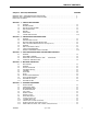
TABLE OF CONTENTS SUBJECT - SECTION, PARAGRAPH PAGE NO. INTRODUCTION - OPERATION/SAFETY PRECAUTIONS . . . . . . . . . . . . . . . . . . . . . . . . . . . . . . . . . . . . . . . . . . . . .a INTRODUCTION - MAINTENANCE SAFETY PRECAUTIONS . . . . . . . . . . . . . . . . . . . . . . . . . . . . . . . . . . . . . . . . . . .b EFFECTIVITY CHANGES . . . . . . . . . . . . . . . . . . . . . . . . . . . . . . . . . . . . . . . . . . . . . . . . . . . . . . . . . . . . . . . . . . . . . . .
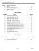
TABLE OF CONTENTS (Continued) SECTION 6 - EMERGENCY PROCEDURES 6.1 6.2 6.3 6.4 6.5 GENERAL. . . . . . . . . . . . . . . . . . . . . . . . . . . . . . . . . . . . . . . . . . . . . . . . . . . . . . . . . . . . . . . . . . . . .6-1 EMERGENCY TOWING PROCEDURES. . . . . . . . . . . . . . . . . . . . . . . . . . . . . . . . . . . . . . . . . . . . . 6-1 EMERGENCY CONTROLS AND THEIR LOCATIONS. . . . . . . . . . . . . . . . . . . . . . . . . . . . . . . . . . .6-1 EMERGENCY OPERATION. . . . . . . . . . . . . .
SECTION 1 - SAFETY PRECAUTIONS SECTION 1. SAFETY PRECAUTIONS 1.1 GENERAL. 1.2 This section prescribes the proper and safe practices for major areas of machine usage which have been divided into two basic categories; Driving and Operation. In order to promote proper usage of the machine, it is mandatory that a daily routine be established based on instruction given in this section.
SECTION 1 - SAFETY PRECAUTIONS 1.3 ELECTROCUTION HAZARD. Table Minimum safe approach distances (M.S.A.D.) to energized (exposed or insulated) power lines and parts. Table 1-1. Minimum safe approach distance (M.S.A.D.) to energized (exposed or insulated) power lines and parts.
SECTION 1 - SAFETY PRECAUTIONS • BEFORE OPERATION CHECK WORK AREA FOR OVERHEAD ELECTRIC LINES, MACHINE TRAFFIC SUCH AS BRIDGE CRANES, HIGHWAY, RAILWAY AND CONSTRUCTION EQUIPMENT. • PRECAUTIONS TO AVOID ALL KNOWN HAZARDS IN THE WORK AREA MUST BE TAKEN BY THE OPERATOR AND HIS SUPERVISOR BEFORE STARTING THE WORK. • DO NOT OPERATE THIS MACHINE UNLESS IT HAS BEEN SERVICED AND MAINTAINED ACCORDING TO THE MANUFACTURERS SPEC IFI CATIONS AND SCHEDULE.
SECTION 1 - SAFETY PRECAUTIONS 1.5 DRIVING. • WATCH FOR OBSTRUCTIONS AROUND MACHINE AND OVERHEAD WHEN DRIVING. • ALWAYS POSITION BOOM OVER REAR (DRIVE) AXLE IN LINE WITH DIRECTION OF TRAVEL. REMEMBER, IF BOOM IS OVER FRONT (STEER) AXLE, DIRECTION OF STEER AND DRIVE MOVEMENT WILL BE OPPOSITE FROM NORMAL OPERATION. • DO NOT USE DRIVE FUNCTION TO POSITION PLATFORM CLOSE TO OBSTACLES. USE TELESCOPE OR SWING INSTEAD.
SECTION 1 - SAFETY PRECAUTIONS 1.6 OPERATION. • READ YOUR MANUAL, UNDERSTAND WHAT YOUVE READ - THEN BEGIN OPERATIONS. • DO NOT OPERATE ANY MACHINE ON WHICH DANGER, WARNING, CAUTION OR INSTRUCTION PLACARDS OR DECALS ARE MISSING OR ILLEGIBLE. • PRIOR TO ENTERING AND EXITING PLATFORM AT GROUND LEVEL, FULLY LOWER UPPER BOOM AND MID/LOWER BOOM. WITH BOOM LIFT IN THIS CONFIGURATION, ENTER AND/OR EXIT PLATFORM THROUGH GATE OPENING.
SECTION 1 - SAFETY PRECAUTIONS • NEVER PLACE HANDS OR ARMS IN TOWER BOOM OR UPRIGHT MECHANISM. • THE OPERATOR IS RESPONSIBLE TO AVOID OPERATING MACHINE OVER GROUND PERSONNEL AND TO WARN THEM NOT TO WORK, WALK OR STAND UNDER A RAISED BOOM OR PLATFORM. POSITION BARRICADES ON FLOOR IF NECESSARY. • NEVER SLAM A CONTROL SWITCH OR LEVER THROUGH NEUTRAL TO THE OPPOSITE DIRECTION. ALWAYS RETURN SWITCH TO NEUTRAL AND STOP; THEN MOVE SWITCH TO THE DESIRED POSITION. OPERATE LEVERS WITH SLOW, EVEN PRESSURE.
SECTION 1 - SAFETY PRECAUTIONS • ENSURE MACHINE IS POSITIONED ON A FIRM, LEVEL AND UNIFORM SUPPORTING SURFACE BEFORE RAISING OR EXTENDING BOOM. • EXERCISE EXTREME CAUTION AT ALL TIMES TO PREVENT OBSTACLES FROM STRIKING OR INTERFERING WITH OPERATING CONTROLS AND PERSONS IN PLATFORM. • ENSURE THAT OPERATORS OF OTHER OVERHEAD AND FLOOR MACHINES ARE AWARE OF THE AERIAL PLATFORMS PRESENCE. DISCONNECT POWER TO OVERHEAD CRANES. PLACE BARRICADES ON FLOOR IF NECESSARY.
SECTION 1 - SAFETY PRECAUTIONS • DO NOT REMOVE, MODIFY, OR DISABLE FOOTSWITCH BY BLOCKING OR ANY OTHER MEANS. • DO NOT ASSIST A STUCK OR DISABLED MACHINE BY PUSHING OR PULLING EXCEPT BY PULLING AT CHASSIS TIE-DOWN LUGS. • NEVER ATTEMPT USING BOOM AS A CRANE. STRUCTURAL DAMAGE OR TIPPING MAY OCCUR. • NEVER POSITION LADDERS, STEPS, OR SIMILAR ITEMS ON UNIT TO PROVIDE ADDITIONAL REACH FOR ANY PURPOSE. NO CIRCUS ACTS IN PLATFORM. • STOW BOOM AND SHUT OFF ALL POWER BEFORE LEAVING MACHINE.
SECTION 1 - SAFETY PRECAUTIONS • KEEP OIL, MUD AND SLIPPERY SUBSTANCES CL EA NE D FR OM F OO TW EA R A N D PL ATF OR M FLOOR. • NEVER ATTEMPT TO FREE A MACHINE STUCK IN SOFT GROUND OR ASSIST A MACHINE UP A STEEP HILL OR RAMP BY USING BOOM LIFT, TELESCOPE, OR SWING FUNCTIONS. • NEVER WALK THE BOOM TO GAIN ACCESS TO OR LEAVE PLATFORM. • NEVER ATTACH WIRE, CABLE, OR ANY SIMILAR ITEMS TO PLATFORM. • DO NOT PLACE BOOM OR PLATFORM AGAINST ANY STRUCTURE TO STEADY PLATFORM OR SUPPORT STRUCTURES.
SECTION 1 - SAFETY PRECAUTIONS 1.7 TOWING AND HAULING. • DO NOT TOW THIS MACHINE, EXCEPT IN AN EMERGENCY. SEE SECTION 6 FOR EMERGENCY TOWING PROCEDURES. 1-10 • ENSURE UPPER AND LOWER BOOMS ARE TIED DOWN SECURELY BEFORE HAULING MACHINE ON TRUCK OR TRAILER. REFER TO SECTION 4 FOR SPECIFIC MACHINE TIE DOWN PROCEDURES.
SECTION 2 - PREPARATION AND INSPECTION SECTION 2. PREPARATION AND INSPECTION 2.1 GENERAL. This section provides the necessary information needed by those personnel that are responsible to place the machine in operation readiness, and lists checks that are performed prior to use of the machine. It is important that the information contained in this section be read and understood before any attempt is made to operate the machine.
SECTION 2 - PREPARATION AND INSPECTION Turntable. 7. Check Upper Boom lift cylinder and cross pins and hydraulic lines for damage, wear, lubrication, leakage and security. 1. Check turntable for damage, loose or missing parts, and security. Check lift cylinders and hydraulic lines for damage, leakage and security. Check swing drive motor for damage, loose or missing parts, hydraulic lines and component housings for evidence of leakage; worm gear for proper mesh with swing gear. 2.
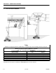
SECTION 2 - PREPARATION AND INSPECTION Figure 2-1. Boom Nomenclature.
SECTION 2 - PREPARATION AND INSPECTION Figure 2-2. Boom Nomenclature. (40/n40/45 electric) 9. Check all pin and shaft retaining hardware for security and wear. 10. Check Upper Upright, cross pins and hydraulic lines for damage, wear, lubrication, leakage and security. 11. Check Upper Upright for damage, wear, lubrication and security. 15. Check Upper Boom for damage, missing parts and security. 16. Check Upper Boom wear pads for damage, missing parts and security. 12.
SECTION 2 - PREPARATION AND INSPECTION 2. Placards. 2. Check control switches and levers for damage, loose or missing parts and security. Assure that lever and lever lock functions properly. Keep all information and operating placards clean and unobstructed. Cover when spray painting or shot blasting to protect legibility. 3. Check control switches, levers and electrical connections for tightness and evidence of corrosion, and wiring for defects and chafing damage.
SECTION 2 - PREPARATION AND INSPECTION Figure 2-3. Daily Walk-Around Inspection.
SECTION 2 - PREPARATION AND INSPECTION 7. Telescope Cylinder and Power Track 35/n35/ 40/n40/45 electric - No visible damage; no loose or missing hardware. GENERAL. Begin your Walk-Around Inspection at item 1, as noted on the diagram. Continue to your right (counterclockwise viewed from the top) checking each item in sequence for the conditions listed in the following checklist. 8. Limit Switches - Switches operable; no visible damage. 9.
SECTION 2 - PREPARATION AND INSPECTION 21. Boom/Upright - No visible damage; All pins 34. Swing Motor and Worm Gear - No loose or properly secured. Upright in vertical position. If Upright does not rest on stop with machine in the stowed position, this indicates upright is out of plumb. (See Section 2-20 in service manual 3120743, for Boom Synchronizing procedure.) missing hardware; no visible damage; evidence of proper lubrication. 22.
SECTION 2 - PREPARATION AND INSPECTION 2.5 8. On models (35/n35/40/n40/45 electric), check rotator for smooth operation and assure platform will rotate 75 degrees in both directions from centerline of boom. DAILY FUNCTIONAL CHECK. A functional check of all systems should be performed, once the walk-around inspection is complete, in an area free of overhead and ground level obstructions. First, using the ground controls, check all functions controlled by the ground controls.
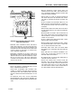
SECTION 2 - PREPARATION AND INSPECTION 2.7 Battery Charging, Daily. BATTERY MAINTENANCE AND CHARGING. NOTE: To avoid excessive battery charging time, do not allow batteries to become completely discharged. TO AVOID INJURY FROM AN EXPLOSION, DO NOT SMOKE OR ALLOW SPARKS OR A FLAME NEAR BATTERY DURING SERVICING. ALWAYS WEAR EYE AND HAND PROTECTION WHEN SERVICING BATTERIES. To avoid electrolyte overflow, add distilled water to batteries after charging.
SECTION 2 - PREPARATION AND INSPECTION Figure 2-4. Lubrication Chart - 30 electric.
SECTION 2 - PREPARATION AND INSPECTION Figure 2-4. Lubrication Chart - 30 electric.
SECTION 2 - PREPARATION AND INSPECTION Figure 2-4. Lubrication Chart - 35/n35 electric.
SECTION 2 - PREPARATION AND INSPECTION Figure 2-4. Lubrication Chart - 35/n35 electric.
SECTION 2 - PREPARATION AND INSPECTION Figure 2-4. Lubrication Chart - 40/n40/45 electric.
SECTION 2 - PREPARATION AND INSPECTION Figure 2-4. Lubrication Chart - 40/n40/45 electric.
SECTION 2 - PREPARATION AND INSPECTION Figure 2-5.
SECTION 2 - PREPARATION AND INSPECTION This page left blank intentionally.
SECTION 3 - USER RESPONSIBILITIES AND MACHINE CONTROLS SECTION 3. USER RESPONSIBILITIES AND MACHINE CONTROLS 3.1 3. Knowledge and understanding of all safety work rules of the employer and of Federal, State and local statutes, including training in the recognition and avoidance of potential hazards in the work place; with particular attention to the work to be performed. GENERAL.
SECTION 3 - USER RESPONSIBILITIES AND MACHINE CONTROLS 3.3 OPERATING CHARACTERISTICS AND LIMITATIONS. TO AVOID FORWARD OR BACKWARD UPSET, DO NOT OVERLOAD MACHINE, OPERATE ON OUT-OF-LEVEL SURFACE OR OPERATE WITH THE BOOM UPRIGHT TILTING. (SEE FIGURE 4-2. UPRIGHT POSITIONING). General. A thorough knowledge of the operating characteristics and limitations of the machine is always the first requirement for any user, regardless of the users experience with similar types of equipment. Placards.
SECTION 3 - USER RESPONSIBILITIES AND MACHINE CONTROLS Figure 3-1. Position of Least Forward Stability, 30 electric.
SECTION 3 - USER RESPONSIBILITIES AND MACHINE CONTROLS Figure 3-1. Position of Least Forward Stability, 35/n35 electric.
SECTION 3 - USER RESPONSIBILITIES AND MACHINE CONTROLS Figure 3-1. Position of Least Forward Stability, 40/n40/45 electric.
SECTION 3 - USER RESPONSIBILITIES AND MACHINE CONTROLS Figure 3-2. Position of Least Backward Stability, 30 electric.
SECTION 3 - USER RESPONSIBILITIES AND MACHINE CONTROLS Figure 3-2. Position of Least Backward Stability, 35/n35 electric.
SECTION 3 - USER RESPONSIBILITIES AND MACHINE CONTROLS Figure 3-2. Position of Least Backward Stability, 40/n40/45 electric.
SECTION 3 - USER RESPONSIBILITIES AND MACHINE CONTROLS 3. Rotate. (35/n35/40/n40/45 electric) 7. Telescope. (35/n35/40/n40/45 electric) A three position ROTATE control switch permits rotation of the platform when positioned to left or right. Provides for extension and retraction of Upper Boom when positioned to IN or OUT. 4. Platform Leveling Override. (35/n35/40/n40/45 electric) 8. Swing. The SWING control switch provides 360 degrees non-continuous turntable rotation.
SECTION 3 - USER RESPONSIBILITIES AND MACHINE CONTROLS Figure 3-3.
SECTION 3 - USER RESPONSIBILITIES AND MACHINE CONTROLS Platform Control Station. (See Figure 3-4) 6. Swing. The SWING control switch provides 360 degrees non-continuous turntable rotation. To activate SWING, position switch to LEFT or RIGHT. 1. Footswitch. A safety feature, the footswitch must be depressed before boom, drive or steer functions will operate. NOTE: When Lift or Swing is being operated, Drive will not function.
SECTION 3 - USER RESPONSIBILITIES AND MACHINE CONTROLS 11. Machine Out Of Level. This red illuminator indicates that the chassis is on a slope (over 5 degrees). If the boom is above horizontal and the machine is on a 5 degree slope, an alarm will sound and CREEP is automatically activated. 12. Horn. A push-type HORN switch supplies electrical power to an audible warning device when pressed. 13. Circuit Breakers. The circuit breakers open (pop out) to indicate a short or overload somewhere on the machine.
SECTION 3 - USER RESPONSIBILITIES AND MACHINE CONTROLS Figure 3-4. 3120860 Platform Control Console.
SECTION 3 - USER RESPONSIBILITIES AND MACHINE CONTROLS Table 3-1. 3-14 Control Panel Symbols.
SECTION 3 - USER RESPONSIBILITIES AND MACHINE CONTROLS Table 3-1. 3120860 Control Panel Symbols.
SECTION 3 - USER RESPONSIBILITIES AND MACHINE CONTROLS Table 3-1. 3-16 Control Panel Symbols.
SECTION 4 - MACHINE OPERATION SECTION 4. MACHINE OPERATION 4.1 DESCRIPTION. This JLG Lift is EE Rated and Certified By Underwriters Laboratories. This machine is a self-propelled hydraulic lift equipped with a work platform on the end of an elevating, articulating and rotating boom. The JLG Lift’s intended purpose is to position personnel with their tools and supplies at positions above ground level, and can be used to reach work areas located above machinery or equipment.
SECTION 4 - MACHINE OPERATION Platform/Ground Select Switch. The Platform/Ground Select switch functions to direct battery power to the desired control station when the POWER/EMERGENCY STOP switch is pulled out (on). With the switch held in the GROUND position battery power is supplied to the ground control station. When the switch is in the PLATFORM position, battery power is supplied to the platform control station. Motor Activation.
SECTION 4 - MACHINE OPERATION Figure 4-1. Grade and Side Slopes. 4.6 2. Leveling DOWN. Depress footswitch to lower platform, position PLATFORM/LEVEL control switch to DOWN and hold until platform is level. PLATFORM. Loading From Ground Level. 1. Position chassis on a smooth, firm and level surface. Platform Rotation. (35/n35/40/n40/45 electric) NOTE: Telescope the boom on the MODEL 35 electric approximately 5 ft. ( 1.5 m) for platform access. 1.
SECTION 4 - MACHINE OPERATION TRAVELING WITH BOOM BELOW HORIZONTAL IS PERMITTED ON GRADES AND SIDE SLOPES SPECIFIED ON WARNING PLACARD AT PLATFORM. TO AVOID SERIOUS INJURY, DO NOT OPERATE MACHINERY IF ANY CONTROL LEVER OR TOGGLE SWITCH CONTROLLING PLATFORM MOVEMENT DOES NOT RETURN TO THE ‘OFF’ OR NEUTRAL POSITION WHEN RELEASED. TO AVOID A COLLISION AND INJURY IF PLATFORM DOES NOT STOP WHEN A CONTROL SWITCH OR LEVER IS RELEASED, REMOVE FOOT FROM FOOTSWITCH OR USE EMERGENCY STOP SWITCH TO STOP THE MACHINE.
SECTION 4 - MACHINE OPERATION Figure 4-2. Upright Positioning Models 40e and 45e.
SECTION 4 - MACHINE OPERATION Secure lower boom by running a suitable tie down strap over the lower boom and under the lift cylinder as shown and secure to truck or trailer. DO NOT OVERTIGHTEN OR DAMAGE WILL OCCUR TO BOOM OR PLATFORM. Platform/Boom Tie Down (Model 35electric). (See Figure 4-3) Tilt platform forward all the way toward the boom and telescope fly boom section out until rotator support rests on a 6" x 6" (15cm x 15cm) wooden block.
SECTION 4 - MACHINE OPERATION Figure 4-3. Chassis & Platform Tie Down.
SECTION 4 - MACHINE OPERATION Figure 4-4. Lifting Chart.
SECTION 5 - OPTIONAL EQUIPMENT SECTION 5. OPTIONAL EQUIPMENT 5.7 WHEN ADDING AN ELECTRICAL OR ELECTRONIC OPTION TO THE MACHINE, DO NOT GROUND THE DEVICE TO THE MACHINE CHASSIS. AN ELECTRICAL OR ELECTRONIC DEVICE THAT IS GROUNDED TO THE CHASSIS IS SEEN BY THE SEVCON AS A SHORT CIRCUIT AND WILL CAUSE A FAULT CODE TO APPEAR. GROUND ALL ELECTRICAL OR ELECTRONIC DEVICES TO THE APPROPRIATE TERMINAL OF THE SEVCON CONTROLLER.
SECTION 5 - OPTIONAL EQUIPMENT This page intentionally left blank.
SECTION 6 - EMERGENCY PROCEDURES SECTION 6. EMERGENCY PROCEDURES 6.1 Ground Control Station. GENERAL. This section provides information on the procedures to be followed and on the systems and controls to be used in the event an emergency situation is encountered during machine operation.
SECTION 6 - EMERGENCY PROCEDURES Manual Swing Override. (30/35/40/n40/45 electric) Platform or Boom Caught Overhead: The manual swing override is used to manually swing boom and turntable assembly in the event of a total power failure when the platform is positioned over a structure or obstacle. To operate the manual swing override, proceed as follows: 1. Using a 7/8 inch socket and ratchet wrench, locate nut on swing worm gear on left side of machine.
JLG Industries, Inc. TRANSFER OF OWNERSHIP To: JLG, Gradall, Lull and Sky Trak product owner: If you now own, but ARE NOT the original purchaser of the product covered by this manual, we would like to know who you are. For the purpose of receiving safety-related bulletins, it is very important to keep JLG Industries, Inc. updated with the current ownership of all JLG products. JLG maintains owner information for each JLG product and uses this information in cases where owner notification is necessary.
Corporate Office JLG Industries, Inc. 1 JLG Drive McConnellsburg PA. 17233-9533 USA Phone: (717) 485-5161 Customer Support Toll Free: (877) 554-5438 Fax: (717) 485-6417 JLG Worldwide Locations JLG Industries (Australia) P.O. Box 5119 11 Bolwarra Road Port Macquarie N.S.W.