
Service Manual Instruction Manual


Table Of Contents
- Section A. Introduction - Maintenance Safety Precautions
- Section 1. Specifications
- Section 2. General
- Section 3. Chassis & Turntable
- 3.1 Tires And Wheels
- 3.2 Torque Hub
- Oil Information
- Roll and Leak Testing
- Tightening and Torquing Bolts
- Main Disassembly
- Output Carrier Disassembly
- Input Carrier Disassembly
- Hub-Spindle Disassembly
- Spindle-Brake Disassembly
- Cover Disassembly
- Cover Assembly
- Input Carrier Sub-Assembly
- Output Planet Gear Sub-Assembly
- Spindle - Brake Sub-Assembly
- Hub-Spindle Sub-Assembly
- Cover Sub-Assembly
- Main Assembly
- Integral Brake Check
- 3.3 Free Wheeling Option
- 3.4 Drive Motor
- 3.5 Oscillating Axle Bleeding Procedure and Lockout Test
- 3.6 Steer Adjustments
- 3.7 Swing Drive
- 3.8 Swing Bearing
- 3.9 Swing Brake - Mico
- 3.10 Rotary Coupling
- 3.11 Generator
- 3.12 Deutz D2.9 L4 Engine
- 3.13 Deutz D2011 Engine
- 3.14 Spark Arrester Cleaning Instructions
- 3.15 Glow Plugs
- 3.16 Deutz EMR 2
- 3.17 Bio Fuel in Deutz Engines
- 3.18 GM Engine General Maintenance
- 3.19 GM Engine Dual Fuel System
- Fuel Filter
- Direct Electronic Pressure Regulator (DEPR)
- Air Fuel Mixer
- Electronic Throttle Control (ETC)
- Electric Lock Off
- Engine Control Module (ECM)
- Heated Exhaust Gas Oxygen Sensor
- Gasoline Multi Point Fuel Injection System (MPFI)
- Gasoline Fuel Pump
- Gasoline Pressure And Temperature Sensor Manifold
- Fuel Filter
- Fuel Injector Rail
- Fuel Injector
- 3.20 GM Engine Fuel System Repair
- Propane Fuel System Pressure Relief
- Propane Fuel System Leak Test
- Propane Fuel Filter Replacement
- Direct Electronic Pressure Regulator (DEPR) Maintenance And Inspection
- Check/Drain Oil Build-Up In 2-Stage Vaporizer
- Air Fuel Mixer/Throttle Control Device Maintenance And Inspection
- Exhaust System And Catalytic Converter Inspection And Maintenance
- Temperature Manifold Absolute Pressure (TMAP) Sensor
- Throttle Body (ETC) Replacement
- Mixer Replacement
- Electronic Pressure Regulator (EPR) Replacement
- Regulator Replacement
- Coolant Hose Replacement
- Vapor Hose Replacement
- Engine Control Module Replacement
- Heated Exhaust Gas Oxygen Sensor Replacement
- 3.21 GM Engine LPG Fuel System Diagnosis
- Section 4. Boom & Platform
- Section 5. Hydraulics
- 5.1 O-Ring Lubrication
- 5.2 Cylinders - Theory of Operation
- 5.3 Cylinder Checking Procedure
- 5.4 Cylinder Removal and Installation
- Cylinder Locations
- Main Boom Telescope Cylinder Removal
- Main Boom Telescope Cylinder Installation
- Main Boom Lift Cylinder Removal
- Main Boom Lift Cylinder Installation
- Upright Level Cylinder Removal
- Upright Level Cylinder Installation
- Tower Boom Lift Cylinder Removal
- Tower Lift Cylinder Installation
- Tower Telescope Cylinder Removal
- Tower Telescope Cylinder Installation
- 5.5 Hydraulic Cylinder repair
- Tower Boom Lift Cylinder
- Cleaning and Inspection
- Assembly
- Upright Level Cylinder
- Cleaning and Inspection
- Assembly
- Master Cylinder
- Cleaning and Inspection
- Assembly
- Main Boom Lift Cylinder
- Cleaning and Inspection
- Assembly
- Main Boom Telescope Cylinder
- Cleaning and Inspection
- Assembly
- Tower Boom Telescope Cylinder
- Cleaning and Inspection
- Assembly
- Platform Level (Slave) Cylinder
- Cleaning and Inspection
- Assembly
- Jib Lift Cylinder (AJ Only)
- Cleaning and Inspection
- Assembly
- Steer Cylinder
- Cleaning and Inspection
- Assembly
- Axle Lockout Cylinder
- 5.6 Hydraulic Pump (Gear)
- 5.7 Variable Pump
- 5.8 Hydraulic Component Start-Up
- 5.9 Pressure Setting Procedures
- Section 6. JLG Control System
- Section 7. Basic Electrical Information & Schematics
SECTION 5 - HYDRAULICS
3121616 – JLG Lift – 5-21
Master Cylinder
DISASSEMBLY
Refer to Figure 5-37. Master Cylinder.
CONTAMINATION MAY DAMAGE EQUIPMENT. DISASSEMBLE CYLINDER ON A
CLEAN WORK SURFACE IN A DIRT FREE WORK AREA.
1. Connect a suitable auxiliary hydraulic power source to
cylinder port block fitting.
DO NOT FULLY EXTEND CYLINDER TO THE END OF STROKE. RETRACT CYLINDER
SLIGHTLY TO AVOID TRAPPING PRESSURE.
2. Operate hydraulic power source and extend cylinder.
Shut down and disconnect power source. Adequately
support cylinder rod, if applicable.
3. If applicable, remove cartridge-type counterbalance
valve and fittings from cylinder port block. Discard O-
rings.
4. Place cylinder barrel in a suitable holding fixture. Tap
around outside of cylinder head retainer with a suitable
hammer to break thread-locking compound.
Figure 5-34. Cylinder Barrel Support
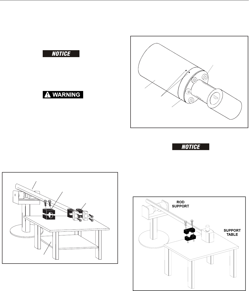
5. Mark cylinder head (1) and barrel (2) with center punch
marks (3) for later realignment. Remove eight cylinder
head cap screws (4).
Figure 5-35. Marking Cylinder for Alignment
PULLING ROD OFF-CENTER CAN DAMAGE PISTON AND CYLINDER BARREL SURFACES.
USE EXTREME CARE WHEN REMOVING CYLINDER ROD, HEAD, AND PISTON.
6. Clamp barrel securely. Pull rod assembly and cylinder
head from barrel.
7. Protect cylinder rod from damage and clamp in a vise or
holding fixture as close to piston as possible.
Figure 5-36. Cylinder Rod Support