Operation and Safety Manual Original Instructions - Keep this manual with the machine at all times.
NOTE: This manual also applies to machines with the following Serial Numbers: 0300170082 and 0300170091.
FOREWORD FOREWORD This manual is a very important tool! Keep it with the machine at all times. The purpose of this manual is to provide owners, users, operators, lessors, and lessees with the precautions and operating procedures essential for the safe and proper machine operation for its intended purpose. Due to continuous product improvements, JLG Industries, Inc. reserves the right to make specification changes without prior notification. Contact JLG Industries, Inc. for updated information.
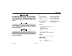
FOREWORD SAFETY ALERT SYMBOLS AND SAFETY SIGNAL WORDS This is the Safety Alert Symbol. It is used to alert you to the potential personal injury hazards. Obey all safety messages that follow this symbol to avoid possible injury or death INDICATES AN IMMINENTLY HAZARDOUS SITUATION. IF NOT AVOIDED, WILL RESULT IN SERIOUS INJURY OR DEATH. THIS DECAL WILL HAVE A RED BACKGROUND. INDICATES A POTENTIALLY HAZARDOUS SITUATION. IF NOT AVOIDED, COULD RESULT IN SERIOUS INJURY OR DEATH.
FOREWORD For: THIS PRODUCT MUST COMPLY WITH ALL SAFETY RELATED BULLETINS. CONTACT JLG INDUSTRIES, INC. OR THE LOCAL AUTHORIZED JLG REPRESENTATIVE FOR INFORMATION REGARDING SAFETYRELATED BULLETINS WHICH MAY HAVE BEEN ISSUED FOR THIS PRODUCT. • Accident Reporting • Product Safety Publications • Current Owner Updates • Questions Regarding Product Safety JLG INDUSTRIES, INC. SENDS SAFETY RELATED BULLETINS TO THE OWNER OF RECORD OF THIS MACHINE. CONTACT JLG INDUSTRIES, INC.
FOREWORD REVISION LOG d Original Issue - April 9, 2013 Revised - October 7, 2013 – JLG Lift – 3121297
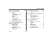
TABLE OF CONTENTS SECTION - PARAGRAPH, SUBJECT PAGE SECTION - PARAGRAPH, SUBJECT SECTION - 1 - SAFETY PRECAUTIONS 1.1 1.2 1.3 1.4 1.5 2.3 GENERAL . . . . . . . . . . . . . . . . . . . . . . . . . . . . . . . . .1-1 PRE-OPERATION . . . . . . . . . . . . . . . . . . . . . . . . . . .1-1 Operator Training and Knowledge . . . . . . . . . . . 1-1 Workplace Inspection . . . . . . . . . . . . . . . . . . . . . 1-2 Machine Inspection . . . . . . . . . . . . . . . . . . . . . . 1-2 OPERATION . . . . . . . . .
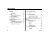
TABLE OF CONTENTS SECTION - PARAGRAPH, SUBJECT 4.5 4.6 4.7 4.8 4.9 4.10 4.11 4.12 4.13 PAGE STEERING . . . . . . . . . . . . . . . . . . . . . . . . . . . . . . . . 4-8 PLATFORM . . . . . . . . . . . . . . . . . . . . . . . . . . . . . . 4-10 Platform Level Adjustment . . . . . . . . . . . . . . . . 4-10 Platform Rotation . . . . . . . . . . . . . . . . . . . . . . . 4-10 BOOM . . . . . . . . . . . . . . . . . . . . . . . . . . . . . . . . . . 4-10 Swinging the Boom . . . . . . . . . . . . . . . . . . .
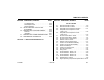
TABLE OF CONTENTS SECTION - PARAGRAPH, SUBJECT 6.5 6.6 6.7 6.8 PAGE SECTION - PARAGRAPH, SUBJECT Tire Replacement . . . . . . . . . . . . . . . . . . . . . . . 6-22 Wheel Replacement . . . . . . . . . . . . . . . . . . . . . 6-23 Wheel Installation . . . . . . . . . . . . . . . . . . . . . . . 6-23 OSCILLATING AXLE LOCKOUT TEST (IF EQUIPPED) . . . . . . . . . . . . . . . . . . . . . . . . . . .6-25 PROPANE FUEL FILTER REPLACEMENT. . . . . . .6-26 Removal . . . . . . . . . . . . . . . . . . . . . . . . .
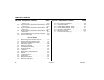
TABLE OF CONTENTS SECTION - PARAGRAPH, SUBJECT 6-3. 6-4. 6-5. 6-6. 6-7. PAGE - Sheet 1 of 2 . . . . . . . . . . . . . . . . . . . . . . . . . . . . 6-10 Engine Operating Temperature Specifications - Deutz - Sheet 2 of 2 . . . . . . . . . . . . . . . . . . . . . . . . . . . . 6-11 Engine Operating Temperature Specifications - GM Sheet 1 of 2 . . . . . . . . . . . . . . . . . . . . . . . . . . . . . 6-12 Engine Operating Temperature Specifications - GM Sheet 2 of 2 . . . . . . . . . . . . . . . . . . . . .
SECTION 1 - SAFETY PRECAUTIONS SECTION 1. SAFETY PRECAUTIONS 1.1 GENERAL 1.2 This section outlines the necessary precautions for proper and safe machine operation and maintenance. For proper machine use, it is mandatory that a daily routine is established based on the content of this manual. A maintenance program, using the information provided in this manual and the Service and Maintenance Manual, must also be established by a qualified person and followed to ensure the machine is safe to operate.
SECTION 1 - SAFETY PRECAUTIONS • Read, understand, and obey all DANGERS, WARNINGS, CAUTIONS, and operating instructions on the machine and in this manual. • Use the machine in a manner which is within the scope of its intended application set by JLG. • All operating personnel must be familiar with the emergency controls and emergency operation of the machine as specified in this manual.
SECTION 1 - SAFETY PRECAUTIONS 1.3 OPERATION • Supplies or tools which extend outside the platform are prohibited unless approved by JLG. General • When driving, always position boom over rear axle in line with the direction of travel. Remember, if boom is over the front axle, steer and drive functions will be reversed. • Do not use the machine for any purpose other than positioning personnel, their tools, and equipment.
SECTION 1 - SAFETY PRECAUTIONS • Before operating the machine, make sure all gates are closed and fastened in their proper position. • Use extreme caution when entering or leaving platform. Be sure that the boom is fully lowered. It may be necessary to telescope out to position the platform closer to the ground for entry/exit. Face the machine, maintain “three point contact” with the machine, using two hands and one foot or two feet and one hand during entry and exit.
SECTION 1 - SAFETY PRECAUTIONS Table 1-1. Minimum Approach Distances (M.A.D.) Voltage Range (Phase to Phase) 0 to 50 KV 10 (3) Over 50KV to 200 KV 15 (5) Over 200 KV to 350 KV 20 (6) Over 350 KV to 500 KV 25 (8) Over 500 KV to 750 KV 35 (11) Over 750 KV to 1000 KV 45 (14) NOTE: • Maintain distance from electrical lines, apparatus, or any energized (exposed or insulated) parts according to the Minimum Approach Distance (MAD) as shown in Table 11.
SECTION 1 - SAFETY PRECAUTIONS • The minimum approach distance may be reduced if insulating barriers are installed to prevent contact, and the barriers are rated for the voltage of the line being guarded. These barriers shall not be part of (or attached to) the machine. The minimum approach distance shall be reduced to a distance within the designed working dimensions of the insulating barrier.
SECTION 1 - SAFETY PRECAUTIONS • Do not elevate platform or drive with platform elevated while on a sloping, uneven, or soft surface. • If boom assembly or platform is in a position that one or more wheels are off the ground, all persons must be removed before attempting to stabilize the machine. Use cranes, forklift trucks, or other appropriate equipment to stabilize machine. • Before driving on floors, bridges, trucks, and other surfaces, check allowable capacity of the surfaces.
SECTION 1 - SAFETY PRECAUTIONS • Use the boom functions, not the drive function, to position the platform close to obstacles. • Always post a lookout when driving in areas where vision is obstructed. • Keep non-operating personnel at least 6 ft. (1.8m) away from machine during all driving and swing operations. • Limit travel speed according to conditions of ground surface, congestion, visibility, slope, location of personnel, and other factors which may cause collision or injury to personnel.
SECTION 1 - SAFETY PRECAUTIONS 1.5 ADDITIONAL HAZARDS / SAFETY • Do not refuel the machine with the engine running. • Battery fluid is highly corrosive. Avoid contact with skin and clothing at all times. • Do not use machine as a ground for welding. • When performing welding or metal cutting operations, precautions must be taken to protect the chassis from direct exposure to weld and metal cutting spatter. 3121297 – JLG Lift – • Charge batteries only in a well ventilated area.
SECTION 1 - SAFETY PRECAUTIONS DO NOT OPERATE THE MACHINE WHEN WIND CONDITIONS EXCEED 28 MPH (12.5 M/S). Table 1-2. Beaufort Scale (For Reference Only) 1-10 Wind Speed Beaufort Number mph m/s 0 0 0-0.2 1 1-3 2 4-7 3 8-12 3.4-5.4 Gentle breeze Leaves and smaller twigs in constant motion 4 13-18 5.5-7.9 Moderate breeze Dust and loose paper raised. Small branches begin to move. Description Land Conditions Calm Calm. Smoke rises vertically 0.3-1.
SECTION 2 - USER RESPONSIBILITIES, MACHINE PREPARATION, AND INSPECTION SECTION 2. USER RESPONSIBILITIES, MACHINE PREPARATION, AND INSPECTION 2.1 PERSONNEL TRAINING 6. The safest means to operate the machine where overhead obstructions, other moving equipment, and obstacles, depressions, holes, dropoffs. The aerial platform is a personnel handling device; so it is necessary that it be operated and maintained only by trained personnel.
SECTION 2 - USER RESPONSIBILITIES, MACHINE PREPARATION, AND INSPECTION 2.2 PREPARATION, INSPECTION, AND MAINTENANCE The following table covers the periodic machine inspections and maintenance recommended by JLG Industries, Inc. Consult local regulations for further requirements for aerial work platforms.
SECTION 2 - USER RESPONSIBILITIES, MACHINE PREPARATION, AND INSPECTION Table 2-1.Inspection and Maintenance Table Type Primary Responsibility Frequency Service Qualification Reference Pre-Start Inspection Before using each day; or whenever there’s an Operator change. User or Operator User or Operator Operator and Safety Manual Pre-Delivery Inspection (See Note) Before each sale, lease, or rental delivery.
SECTION 2 - USER RESPONSIBILITIES, MACHINE PREPARATION, AND INSPECTION Pre-Start Inspection The Pre-Start Inspection should include each of the following: 1. Cleanliness – Check all surfaces for leakage (oil, fuel, or battery fluid) or foreign objects. Report any leakage to the proper maintenance personnel. 2. Structure - Inspect the machine structure for dents, damage, weld or parent metal cracks or other discrepancies. (Domestic only) is enclosed in the weather resistant storage container. 5.
SECTION 2 - USER RESPONSIBILITIES, MACHINE PREPARATION, AND INSPECTION 11. Function Check – Once the “Walk-Around” Inspection is complete, perform a functional check of all systems in an area free of overhead and ground level obstructions. Refer to Section 4 for more specific instructions. IF THE MACHINE DOES NOT OPERATE PROPERLY, TURN OFF THE MACHINE IMMEDIATELY! REPORT THE PROBLEM TO THE PROPER MAINTENANCE PERSONNEL. DO NOT OPERATE THE MACHINE UNTIL IT IS DECLARED SAFE FOR OPERATION. 2.
SECTION 2 - USER RESPONSIBILITIES, MACHINE PREPARATION, AND INSPECTION 2.3 LIMIT SWITCH FUNCTIONAL CHECK 3. Raise main boom, extend and retract telescope. Check for delayed movement of fly section, indicating loose cables. TO AVOID COLLISION AND INJURY IF PLATFORM DOES NOT STOP WHEN A CONTROL SWITCH OR LEVER IS RELEASED, REMOVE FOOT FROM FOOTSWITCH OR USE EMERGENCY STOP TO STOP THE MACHINE. NOTE: Perform checks from ground controls first, then from platform controls. 1.
SECTION 2 - USER RESPONSIBILITIES, MACHINE PREPARATION, AND INSPECTION b. Telescope boom out until 500 lb. (227 kg for ANSI markets and 230 kg for CE and Australia markets) light comes on (may need to used auxiliary power to position boom correctly). c. Mark wear pad location on the fly and mid booms. d. Telescope boom out to full extension. d. Lift boom up until 1000 lb. (454 kg for ANSI markets and 450 kg for CE and Australia markets) light comes on. Boom angle should be 55 degrees to 64 degrees.
SECTION 2 - USER RESPONSIBILITIES, MACHINE PREPARATION, AND INSPECTION Main Boom Angle Switch. d. Lift main boom down until 500 lb. (227 kg for ANSI markets and 230 kg for CE and Australia markets) light comes on. The boom angle at this point should be 45 degrees to 50 degrees. a. Lift main boom to approximately horizontal. b. Telescope boom out until 500 lb. (227 kg for ANSI markets and 230 kg for CE and Australia markets) light comes on (may need to used auxiliary power to position boom correctly).
SECTION 2 - USER RESPONSIBILITIES, MACHINE PREPARATION, AND INSPECTION 1. 2. 3. 4. Platform Platform Control Box Rotator Fly Boom 5. 6. 7. 8. Mid Boom Base Boom Turntable Front Drive/Steer Wheels 9. Rear Drive Wheels 10. Platform Leveling Cylinder 11. Foot Switch Figure 2-1.
SECTION 2 - USER RESPONSIBILITIES, MACHINE PREPARATION, AND INSPECTION 1. 2. 3. 4. Platform Platform Control Box Rotator Jib 5. 6. 7. 8. Fly Boom Mid Boom Base Boom Turntable 9. 10. 11. 12. Front Drive/Steer Wheels Rear Drive Wheels Swing Bearing Platform Leveling Cylinder 13. Jib Lift Cylinder 14. Foot Switch Figure 2-2.
SECTION 2 - USER RESPONSIBILITIES, MACHINE PREPARATION, AND INSPECTION Figure 2-3.
SECTION 2 - USER RESPONSIBILITIES, MACHINE PREPARATION, AND INSPECTION General 4. Jib (If Equipped) - See Inspection Note. Begin the "Walk-Around Inspection" at Item 1, as noted on the diagram. Continue checking each item in sequence for the conditions listed in the following checklist. TO AVOID POSSIBLE INJURY BE SURE MACHINE POWER IS OFF. 5. Power Track - See Inspection Note.
SECTION 2 - USER RESPONSIBILITIES, MACHINE PREPARATION, AND INSPECTION 11. Auxiliary Power Pump - See Inspection Note. 12. Swing Drive Motor and Brake - See Inspection Note. 17. Battery - Proper electrolyte levels if adjustable; cables tight, no visible damage or corrosion. 18. Hydraulic Pump - See Inspection Note. 13. Main Control Valve - See Inspection Note. 14. Turntable Bearing - Evidence of proper lubrication. No evidence of loose bolts or looseness between bearing and structure. 19.
SECTION 2 - USER RESPONSIBILITIES, MACHINE PREPARATION, AND INSPECTION NOTES: 2-14 – JLG Lift – 3121297
SECTION 3 - MACHINE CONTROLS AND INDICATORS SECTION 3. MACHINE CONTROLS AND INDICATORS 3.1 GENERAL NOTE: THE MANUFACTURER HAS NO DIRECT CONTROL OVER MACHINE APPLICATION AND OPERATION. THE USER AND OPERATOR ARE RESPONSIBLE FOR CONFORMING WITH GOOD SAFETY PRACTICES. This section provides the necessary information needed to understand control functions. 3.2 NOTE: CONTROLS AND INDICATORS All machines are equipped with control panels that use symbols to indicate control functions.
SECTION 3 - MACHINE CONTROLS AND INDICATORS Ground Control Station (See Figure 3-1. and Figure 3-2.) NOTE: The Function Enable switch must be held down in order to operate Telescope, Swing, Lift, Jib Lift, Platform Level Override, and Platform Rotate functions. ONLY USE THE PLATFORM LEVELING OVERRIDE FUNCTION FOR SLIGHT LEVELING OF THE PLATFORM. INCORRECT USE COULD CAUSE THE LOAD/OCCUPANT TO SHIFT OR FALL. FAILURE TO DO SO COULD RESULT IN DEATH OR SERIOUS INJURY. 2. Platform Leveling Override 1.
SECTION 3 - MACHINE CONTROLS AND INDICATORS 1. 2. 3. 4. 5. 6. 7. 8. 9. 10. Platform Rotate Platform Leveling Override Not Used Power/Emergency Stop Engine Start/Auxiliary Power/Function Enable Boom Lift Hourmeter Platform/Ground Select Switch Swing Boom Telescope Figure 3-1.
SECTION 3 - MACHINE CONTROLS AND INDICATORS 1. 2. 3. 4. 5. 6. 7. 8. 9. 10. Platform Rotate Platform Leveling Override Jib Power/Emergency Stop Engine Start/Auxiliary Power/Function Enable Boom Lift Hourmeter Platform/Ground Select Switch Swing Boom Telescope Figure 3-2.
SECTION 3 - MACHINE CONTROLS AND INDICATORS NOTE: When Power/Emergency Stop switch is in the “On” position and engine is not running, an alarm will sound, indicating Ignition is “On”. 5. Engine Start/ Auxiliary Power Switch /Function Enable To start the engine, the switch must be held "Up" until the engine starts. To use auxiliary power, the switch must be held “Down” for duration of auxiliary pump use.
SECTION 3 - MACHINE CONTROLS AND INDICATORS NOTE: 6. Lift Control Provides raising and lowering of the boom. 7. Hourmeter Registers the amount of time the machine has been in use, with engine running. By connecting into the oil pressure circuit of the engine, only engine run hours are recorded. The hourmeter registers up to 9,999.9 hours and cannot be reset. 3-6 When the Platform/Ground Select Switch is in the center position, power is shut off to the controls at both operating stations.
SECTION 3 - MACHINE CONTROLS AND INDICATORS NOTE: Lift, Swing, Platform Level, Telescope, Platform Rotator and Auxiliary control switches are spring-loaded and will automatically return to neutral (off) when released. Ground Control Indicator Panel (See Figure 3-3.) 1. No Alternator Output Indicator WHEN OPERATING THE BOOM ENSURE THERE ARE NO PERSONNEL AROUND OR UNDER PLATFORM. Indicates a problem in the charging circuit, and service is required. 2.
SECTION 3 - MACHINE CONTROLS AND INDICATORS 1. 2. 3. 4. No Alternator Output Low Engine Oil Pressure High Engine Coolant Temp. Engine Oil Temp. 5. 6. 7. 8. System Distress Glow Plug Wait to Start Platform Overload Drive and Steer Disable Figure 3-3.
SECTION 3 - MACHINE CONTROLS AND INDICATORS 5. System Distress Indicator 7. Platform Overload Indicator. (If Equipped) The light indicates that the JLG Control System has detected an abnormal condition and a Diagnostic Trouble Code has been set in the system memory. Refer to the Service Manual for instructions concerning the trouble codes and trouble code retrieval. The system distress indicator light will illuminate for 2-3 seconds when the key is positioned to the on position to act as a self test.
SECTION 3 - MACHINE CONTROLS AND INDICATORS Platform Station 2. Steer Select (If Equipped) (See Figure 3-4.) TO AVOID SERIOUS INJURY, DO NOT OPERATE MACHINE IF ANY CONTROL LEVERS OR TOGGLE SWITCHES CONTROLLING PLATFORM MOVEMENT DO NOT RETURN TO THE OFF OR NEUTRAL POSITION WHEN RELEASED. 1. Drive Speed/Torque Select The machine has a three position switch - The forward position gives maximum drive speed. The back position gives maximum torque for rough terrain and climbing grades.
SECTION 3 - MACHINE CONTROLS AND INDICATORS 1. 2. 3. 4. 5. Drive Speed Steer Select Platform Leveling Override Horn Power/Emergency Stop 6. 7. 8. 9. 10. Start/Aux. Power Fuel Select Drive Orientation Override Drive/Steer Telescope 11. 12. 13. 14. 15. Lights Jib Soft Touch Override Soft Touch Indicator Platform Rotate 16. Function Speed 17. Main Lift/Swing Figure 3-4.
SECTION 3 - MACHINE CONTROLS AND INDICATORS 6. Start/Auxiliary Power When pushed forward, the switch energizes the starter motor to start the engine. ONLY USE THE PLATFORM LEVELING OVERRIDE FUNCTION FOR SLIGHT LEVELING OF THE PLATFORM. INCORRECT USE COULD CAUSE THE LOAD/OCCUPANTS TO SHIFT OR FALL. FAILURE TO DO SO COULD RESULT IN DEATH OR SERIOUS INJURY. The Auxiliary Power control switch energizes the electrically operated hydraulic pump. (Switch must be held on for duration of auxiliary pump use.) 3.
SECTION 3 - MACHINE CONTROLS AND INDICATORS NOTE: 8. Drive Orientation Override When the boom is swung over the rear tires or further in either direction, the Drive Orientation indicator will illuminate when the drive function is selected. Push and release the switch, and within 3 seconds move the Drive/Steer control to activate drive or steer. Before driving, locate the black/ white orientation arrows on both the chassis and the platform controls.
SECTION 3 - MACHINE CONTROLS AND INDICATORS NOTE: The Drive joystick is spring loaded and will automatically return to neutral (off) position when released. 12. Jib (If Equipped) Push forward to lift up, pull back to lift down. Variable lift speed is using the Function Speed Control. 9. Drive/Steer Push forward to drive forward, pull back to drive in reverse. Steering is accomplished via a thumb-activated rocker switch on the end of the steer handle. 13.
SECTION 3 - MACHINE CONTROLS AND INDICATORS 15. Platform Rotate NOTE: To operate the Main Boom Lift/Swing joystick, pull up on the locking ring below the handle. NOTE: The Main Boom Lift/Swing joystick is spring loaded and will automatically return to neutral (off) position when released. Provides rotation of the platform when positioned to the right or left. DO NOT OPERATE MACHINE IF DRIVE SPEED /TORQUE SELECT OR FUNCTION SPEED SWITCHES OPERATE WHEN BOOM IS ABOVE HORIZONTAL.
SECTION 3 - MACHINE CONTROLS AND INDICATORS Platform Control Indicator Panel 2. Platform Overload (If equipped) Indicates the platform has been overloaded. (See Figure 3-5., Platform Control Indicator Panel) 1. Tilt Alarm Warning Light and Alarm 3. Capacity Indicator This illuminator indicates that the chassis is on a slope. An alarm will also sound when the chassis is on a slope and the boom is above horizontal.
SECTION 3 - MACHINE CONTROLS AND INDICATORS 1. 2. 3. 4. Tilt Overload Capacity Cable Service 5. 6. 7. 8. Enable Glow Plug Low Fuel Malfunction 9. AC Generator 10. Drive Orientation 11. Creep Figure 3-5.
SECTION 3 - MACHINE CONTROLS AND INDICATORS 4. Cable Service Indicator (If Equipped) 5. Footswitch/Enable Indicator When illuminated, the light indicates the boom cables are loose or broken and must be repaired or adjusted immediately. To operate any function, the footswitch must be depressed and the function selected within seven seconds. The enable indicator shows that the controls are enabled.
SECTION 3 - MACHINE CONTROLS AND INDICATORS 6. Glow Plug/Wait to Start Indicator 9. AC Generator (If Equipped) Indicates the glow plugs are operating. After turning on ignition, wait until light goes out before cranking engine. NOTE: Indicates the generator is in operation. 10. Drive Orientation Indicator Refer to Fuel Reserve/Shut-Off System in Section 4 for more detailed information concerning the Low Fuel Indicator. 7. Low Fuel Indicator (Yellow) Indicates the fuel tank is 1/8 full or less.
SECTION 3 - MACHINE CONTROLS AND INDICATORS NOTES: 3-20 – JLG Lift – 3121297
SECTION 4 - MACHINE OPERATION SECTION 4. MACHINE OPERATION 4.1 DESCRIPTION 4.2 This machine is a self-propelled hydraulic personnel lift equipped with a work platform on the end of an elevating and rotating boom. Capacities The primary operator control station is in the platform. From this control station, the operator can drive and steer the machine in both forward and reverse directions. The operator can raise or lower the main or tower boom or swing the boom to the left or right.
SECTION 4 - MACHINE OPERATION Stability Machine stability is based on two positions which are called FORWARD and BACKWARD stability. The machines position of least FORWARD stability is shown in Figure 4-2., Position of Least Forward Stability, and its position of least BACKWARD stability is shown in Figure 4-1., Position of Least Backward Stability. TO AVOID FORWARD OR BACKWARD TIPPING, DO NOT OVERLOAD MACHINE OR OPERATE THE MACHINE ON AN OUT-OF-LEVEL SURFACE. Figure 4-1.
SECTION 4 - MACHINE OPERATION Figure 4-2.
SECTION 4 - MACHINE OPERATION 4.3 NOTE: ENGINE OPERATION 1. Turn key of Platform/Ground Select switch to Ground. Initial starting should always be performed from the Ground Control station. 2. Pull the Power/Emergency Stop switch to On. Starting Procedure 3. Push the Engine Start switch until engine starts. IF ENGINE FAILS TO START PROMPTLY, DO NOT CRANK FOR AN EXTENDED TIME. SHOULD ENGINE FAIL TO START AGAIN, ALLOW STARTER TO “COOL OFF” FOR 2-3 MINUTES.
SECTION 4 - MACHINE OPERATION 6. From Platform, pull Power/Emergency Stop switch out. 2. Push Power/Emergency Stop switch in. 7. Push the Engine Start switch until engine starts. 3. Turn Platform/Ground Select switch to Off. NOTE: Refer to Engine Manufacturer’s manual for detailed information. Footswitch must be in released (up) position before starter will operate. If starter operates with footswitch in the depressed position, DO NOT OPERATE MACHINE.
SECTION 4 - MACHINE OPERATION • Engine Restart - When the engine shuts down, the operator will be permitted to cycle power and restart the engine for approximately 2 minutes of run time. After the 2 minutes of run time is complete, the operator may cycle power and restart the engine for an additional 2 minutes of run time. The operator can repeat this process until there is no more fuel available.
SECTION 4 - MACHINE OPERATION 1. Gradeability, which is the percent of grade of the incline the machine can climb. Traveling Forward and Reverse 2. Sideslope, which is the angle of the slope the machine can be driven across. DO NOT DRIVE WITH BOOM ABOVE HORIZONTAL EXCEPT ON A SMOOTH, FIRM AND LEVEL SURFACE. TO AVOID LOSS OF TRAVEL CONTROL OR “TIP OVER”, DO NOT DRIVE MACHINE ON GRADES EXCEEDING THOSE SPECIFIED ON THE SERIAL NUMBER PLATE. BE SURE THE TURNTABLE LOCK IS ENGAGED BEFORE ANY EXTENDED TRAVELING.
SECTION 4 - MACHINE OPERATION 4.5 1. Match the black and white direction arrows on both platform control panel and the chassis to determine the direction the machine will travel. STEERING Position thumb switch on Drive/Steer controller to Right for steering right, or to Left for steering left. 2. Push and release the Drive Orientation Override switch. Within 3 seconds, slowly move the Drive control toward the arrow matching the intended direction of machine travel.
SECTION 4 - MACHINE OPERATION Figure 4-3.
SECTION 4 - MACHINE OPERATION 4.6 PLATFORM 4.7 BOOM Platform Level Adjustment DO NOT SWING OR RAISE BOOM ABOVE HORIZONTAL WHEN MACHINE IS OUT OF LEVEL. ONLY USE THE PLATFORM LEVELING OVERRIDE FUNCTION FOR SLIGHT LEVELING OF THE PLATFORM. INCORRECT USE COULD CAUSE THE LOAD/OCCUPANTS TO SHIFT OR FALL. FAILURE TO DO SO COULD RESULT IN DEATH OR SERIOUS INJURY. To Level Up or Down - Position the Platform/ Level control switch Up or Down and hold until the platform is level.
SECTION 4 - MACHINE OPERATION Swinging the Boom Telescoping the Main Boom To swing boom, use Swing control switch to select Right or Left direction. To extend or retract the main boom, use the Main Telescope Control Switch to select In or Out movement. WHEN SWINGING THE BOOM MAKE SURE THERE IS AMPLE ROOM FOR THE BOOM TO CLEAR SURROUNDING WALLS, PARTITIONS AND EQUIPMENT. NOTE: 4.
SECTION 4 - MACHINE OPERATION 4.9 OSCILLATING AXLE LOCKOUT TEST (IF EQUIPPED) 4.11 TOWING (IF EQUIPPED) LOCKOUT SYSTEM TEST MUST BE PERFORMED QUARTERLY, ANY TIME A SYSTEM COMPONENT IS REPLACED, OR WHEN IMPROPER SYSTEM OPERATION IS SUSPECTED. Refer to Section 6.5, Oscillating Axle Lockout Test (If Equipped) for procedure. 4.10 STEER/TOW SELECTOR (IF EQUIPPED) MAXIMUM TOWING SPEED 8 M.P.H. (13 K.M.H.) MAXIMUM TOWING GRADE 25%.
SECTION 4 - MACHINE OPERATION STEER SELECT VALVE Figure 4-4.
SECTION 4 - MACHINE OPERATION 2. Connect tow bar to front of frame with attach pins, and tow bar to towing vehicle. 3. Disconnect drive hubs by inverting disconnect cap.Refer to Figure 4-5., Drive Disconnect Hub. 4. Actuate steer/tow selector valve for towing; pull valve knob OUT to float position. (This opens the steer circuit to reservoir, allowing the steer cylinder rod free travel.) The machine is now in the towing mode. After towing the machine, complete the following: 1.
SECTION 4 - MACHINE OPERATION 4.12 AUXILIARY POWER 3. Depress and hold footswitch. 4. Position Auxiliary Power switch to On and hold. WHEN OPERATING ON AUXILIARY POWER, DO NOT OPERATE MORE THAN ONE FUNCTION AT A TIME. (SIMULTANEOUS OPERATION CAN OVERLOAD THE 12-VOLT AUXILIARY PUMP MOTOR.) 5. Operate appropriate control switch, lever or controller for desired function and hold.
SECTION 4 - MACHINE OPERATION Changing From Gasoline to LP Gas 3. Position Auxiliary Power switch to On and hold. 1. Start engine from Ground Control Station. 4. Operate appropriate control switch or controller for desired function and hold. 5. Release Auxiliary Power switch, and appropriate control switch or controller. 6. Position Power/Emergency Stop switch to Off. 2. Open hand valve on LP gas supply tank by turning counterclockwise. 4.
SECTION 4 - MACHINE OPERATION 4.14 TIE DOWN AND LIFTING When transporting machine, boom must be in the stowed mode with turntable lock pin engaged and machine securely tied down to truck or trailer deck. Four tie down eyes are provided in the frame slab, one at each corner of the machine. (See Figure 4-3. Machine Tie Down.
SECTION 4 - MACHINE OPERATION Figure 4-6.
SECTION 4 - MACHINE OPERATION Figure 4-7.
SECTION 4 - MACHINE OPERATION AUS 26 64 66 38 26 AUS 35 26 48 47 23 6 61 22 21 33 28 34 33 62 43 Figure 4-8.
SECTION 4 - MACHINE OPERATION Figure 4-9.
SECTION 4 - MACHINE OPERATION 101 65 63 17 12 41 24 12 24 27 29 27 15 30 39 43 27,22 28 37 42 39 61 44 45 Figure 4-10.
SECTION 4 - MACHINE OPERATION Table 4-1.
SECTION 4 - MACHINE OPERATION Table 4-1.
SECTION 4 - MACHINE OPERATION Table 4-1.
SECTION 4 - MACHINE OPERATION Table 4-1.
SECTION 4 - MACHINE OPERATION Table 4-2.
SECTION 4 - MACHINE OPERATION Table 4-2.
SECTION 4 - MACHINE OPERATION Table 4-2.
SECTION 4 - MACHINE OPERATION Table 4-2.
SECTION 5 - EMERGENCY PROCEDURES SECTION 5. EMERGENCY PROCEDURES 5.1 GENERAL This section explains the steps to be taken in case of an emergency situation while operating. 5.2 INCIDENT NOTIFICATION JLG Industries, Inc. must be notified immediately of any incident involving a JLG product. Even if no injury or property damage is evident, the factory should be contacted by telephone and provided with all necessary details.
SECTION 5 - EMERGENCY PROCEDURES Platform or Boom Caught Overhead 5.4 If the platform or boom becomes jammed or snagged in overhead structures or equipment, rescue platform occupants prior to freeing the machine. 5-2 EMERGENCY TOWING PROCEDURES Towing this machine is prohibited, unless properly equipped. However, provisions for moving the machine have been incorporated. For specific procedures, refer to Section 4.
SECTION 6 - GENERAL SPECIFICATIONS & OPERATOR MAINTENANCE SECTION 6. GENERAL SPECIFICATIONS & OPERATOR MAINTENANCE 6.1 INTRODUCTION 6.2 This section of the manual provides additional necessary information to the operator for proper operation and maintenance of this machine.
SECTION 6 - GENERAL SPECIFICATIONS & OPERATOR MAINTENANCE Dimensional Data Table 6-1. Operating Specifications Ground Bearing Pressure 600S 660SJ Maximum Drive Speed Electrical System Gross Machine Weight (Approximate) 600S - 2WS 600S - 4WS 660SJ - 2WD 660SJ - 4WS 67 psi (4.7 kg/cm2) 75 psi (5.3 kg/cm2) 4.25 MPH (6.8 Km/hr.) 12VDC 21,425 lbs. (9718 kg) 21,800 lbs. (9888 kg) 26,275 lbs. (11918 kg) 25,910 lbs. (12088 kg) Table 6-2. Dimensional Data Machine Height (Stowed) 8 ft. 5 in. (2.
SECTION 6 - GENERAL SPECIFICATIONS & OPERATOR MAINTENANCE Capacities Engine Data Table 6-3. Capacities Table 6-4. Deutz D2011L04 Specifications Fuel Tank 40 Gallons (151 L) Fuel Hydraulic Oil Tank 26 Gallons (98.4 L) Hydraulic System (Including Tank) 40 Gallons (151.4 L) Torque Hub, Drive* 17 ounces (0.5 L) Oil Capacity Cooling System Crankcase Total Capacity Engine Crankcase Deutz D2011L04 Caterpillar 3044C Diesel w/Filter GM 11 quarts (10.5 L) 10.6 quarts (10 L) 4.5 qts. (4.
SECTION 6 - GENERAL SPECIFICATIONS & OPERATOR MAINTENANCE Tires Table 6-5. GM 3.0L Fuel No. of Cylinders Gasoline or Gasoline/LP Gas 4 BHP Gasoline LP 83 hp @ 3000 rpm 75 hp @ 3000 rpm Bore 4.0 in. (101.6 mm) Stroke 3.6 in. (91.44 mm) Displacement Oil Capacity w/filter Minimum Oil Pressure at idle Hot Compression Ratio Firing Order Max. RPM Fuel Consumption Table 6-6. Tire Specifications Size Load Range Ply Rating Tire Pressure 181 cu.in. (3.0 L, 2966 cc) 4.5 qts. (4.25 L) 6 psi (0.
SECTION 6 - GENERAL SPECIFICATIONS & OPERATOR MAINTENANCE NOTE: When temperatures remain below 20° F (-7 degrees C), JLG Industries recommends the use of Mobil DTE 13M. Aside from JLG recommendations, it is not advisable to mix oils of different brands or types, as they may not contain the same required additives or be of comparable viscosities. If use of hydraulic oil other than Mobilfluid 424 is desired, contact JLG Industries for proper recommendations. Table 6-8. Mobilfluid 424 Specs Table 6-9.
SECTION 6 - GENERAL SPECIFICATIONS & OPERATOR MAINTENANCE Table 6-11. Quintolubric 888-46 Table 6-10. Exxon Univis HVI 26 Specs Specific Gravity 32.1 Density 0.91 @ 15°C (59°F) Pour Point -76°F (-60°C) Pour Point <-20°C (<-4°F) Flash Point 217°F (103°C) Flash Point 275°C (527°F) Fire Point 325°C (617°F) Viscosity NOTE: 6-6 at 40° C 25.8 cSt at 100° C 9.
SECTION 6 - GENERAL SPECIFICATIONS & OPERATOR MAINTENANCE Critical Stability Weights Table 6-13. Critical Stability Weights - 660SJ DO NOT REPLACE ITEMS CRITICAL TO STABILITY WITH ITEMS OF DIFFERENT WEIGHT OR SPECIFICATION (FOR EXAMPLE: BATTERIES, FILLED TIRES, COUNTERWEIGHT, ENGINE & PLATFORM) DO NOT MODIFY UNIT IN ANY WAY TO AFFECT STABILITY. Table 6-12. Critical Stability Weights - 600S LB. KG. Tire and Wheel (Ballasted Only) Size (15 - 19.
SECTION 6 - GENERAL SPECIFICATIONS & OPERATOR MAINTENANCE Serial Number Locations A serial number plate is affixed to the left rear side of the frame. If the serial number plate is damaged or missing, the machine serial number is stamped on the left side of the frame. Figure 6-1.
SECTION 6 - GENERAL SPECIFICATIONS & OPERATOR MAINTENANCE This page left blank intentionally.
SECTION 6 - GENERAL SPECIFICATIONS & OPERATOR MAINTENANCE AMBIENT AIR TEMPERATURE 120°F(49°C) NO OPERATION ABOVE THIS AMBIENT TEMPERATURE 110°F(43°C) 100°F(38°C) 90°F(32°C) ENGINE SPECIFICATIONS SUMMER GRADE FUEL 80°F(27°C) 70°F(21°C) 60°F(16°C) 50°F(10°C) 40°F(4°C) 30°F(-1°C) ENGINE WILL START AND OPERATE UNAIDED AT THIS TEMPERATURE WITH THE RECOMMENDED FLUIDS AND A FULLY CHARGED BATTERY.
SECTION 6 - GENERAL SPECIFICATIONS & OPERATOR MAINTENANCE EXTENDED DRIVING WITH HYDRAULIC OIL TANK TEMPERATURES OF 180° F (82°C) OR ABOVE. 180° F (82° C) (HYD. OIL TANK TEMP.
SECTION 6 - GENERAL SPECIFICATIONS & OPERATOR MAINTENANCE AMBIENT AIR TEMPERATURE NO OPERATION ABOVE THIS AMBIENT TEMPERATURE 120 F(49 C) 110 F(43 C) 100 F(38 C) 90 F(32 C) 80 F(27 C) 70 F(21 C) ENGINE SPECIFICATIONS 60 F(16 C) 50 F(10 C) 40 F(4 C) ENGINE WILL START AND OPERATE ON LPG UNAIDED AT THIS TEMPERATURE WITH THE RECOMMENDED FLUIDS AND A FULLY CHARGED BATTERY. NOTE: THIS IS THE LOWEST ALLOWABLE OPERATING TEMPERATURE ON LPG.
SECTION 6 - GENERAL SPECIFICATIONS & OPERATOR MAINTENANCE EXTENDED DRIVING WITH HYDRAULIC OIL TANK TEMPERATURES OF 180°F (82° C) OR ABOVE. 180° F(82° C) (HYD. OIL TANK TEMP.
SECTION 6 - GENERAL SPECIFICATIONS & OPERATOR MAINTENANCE Figure 6-6.
SECTION 6 - GENERAL SPECIFICATIONS & OPERATOR MAINTENANCE 6.3 NOTE: OPERATOR MAINTENANCE 1. Swing Bearing The following numbers correspond to those in Figure 66., Operator Maintenance & Lubrication Diagram. Table 6-14. Lubrication Specifications KEY SPECIFICATIONS MPG Multipurpose Grease having a minimum dripping point of 350° F (177° C). Excellent water resistance and adhesive qualities, and being of extreme pressure type. (Timken OK 40 pounds minimum.
SECTION 6 - GENERAL SPECIFICATIONS & OPERATOR MAINTENANCE 2. Wheel Bearings (If equipped) 3. Swing Drive Hub Lube Point(s) - Repack Capacity - A/R Lube - MPG Interval - Every 2 years or 1200 hours of operation 6-16 Lube Point(s) - Level/Fill Plug Capacity - 43 oz. (1.
SECTION 6 - GENERAL SPECIFICATIONS & OPERATOR MAINTENANCE 4. Wheel Drive Hub 5. Hydraulic Return Filter Lube Point(s) - Level/Fill Plug Capacity - 17 oz. (1/2 Full) Lube - EPGL Interval - Check level every 3 months or 150 hrs of operation; change every 2 years or 1200 hours of operation Interval - Change after first 50 hrs. and every 6 months or 300 hrs. thereafter or as indicated by Condition Indicator.
SECTION 6 - GENERAL SPECIFICATIONS & OPERATOR MAINTENANCE 7. Hydraulic Tank 6. Hydraulic Charge Filter NORMAL OPERATING RANGE WITH BOOM IN STOWED POSITION Interval - Change after first 50 hrs. and every 6 months or 300 hrs. thereafter or as indicated by Condition Indicator. 6-18 – JLG Lift – Lube Point(s) - Fill Cap Capacity - 26 gal. Tank; 40 gal. System Lube - HO Interval - Check Level daily; Change every 2 years or 1200 hours of operation.
SECTION 6 - GENERAL SPECIFICATIONS & OPERATOR MAINTENANCE 8. Oil Change w/Filter - Deutz 9. Oil Change w/Filter - GM Lube Point(s) - Fill Cap/Spin-on Element Capacity - 11 Quarts Crankcase; 5 Quarts Cooler Lube - EO Interval - Every Year or 1200 hours of operation Comments - Check level daily/Change in accordance with engine manual. 3121297 – JLG Lift – Lube Point(s) - Fill Cap/Spin-on Element (JLG P/N 7027965) Capacity - 4.5 qt. (4.
SECTION 6 - GENERAL SPECIFICATIONS & OPERATOR MAINTENANCE 10. Fuel Filter - Deutz 12. Air Filter Lube Point(s) - Replaceable Element Interval - Every 6 months or 300 hours of operation or as indicated by the condition indicator Lube Point(s) - Replaceable Element Interval - Every Year or 600 hours of operation 11.
SECTION 6 - GENERAL SPECIFICATIONS & OPERATOR MAINTENANCE 13. Electronic Pressure Regulator (LP only) 14. Fuel Filter (Propane) - GM Engine Interval - 3 Months or 150 hours of operation Comments - Drain oil build up. Refer to Section 6.6, Propane Fuel Filter Replacement 3121297 – JLG Lift – Interval - 3 Months or 150 hours of operation Comments - Replace filter. Refer to Section 6.
SECTION 6 - GENERAL SPECIFICATIONS & OPERATOR MAINTENANCE 6.4 TIRES & WHEELS • any damage to the bead area cords of the tire Tire Inflation The air pressure for pneumatic tires must be equal to the air pressure that is stenciled on the side of the JLG product or rim decal for safe and proper operational characteristics. Tire Damage For pneumatic tires, JLG Industries, Inc.
SECTION 6 - GENERAL SPECIFICATIONS & OPERATOR MAINTENANCE by JLG. Due to size variations between tire brands, both tires on the same axle should be the same. Wheel Replacement The rims installed on each product model have been designed for stability requirements which consist of track width, tire pressure, and load capacity. Size changes such as rim width, center piece location, larger or smaller diameter, etc., without written factory recommendations, may result in an unsafe condition regarding stability.
SECTION 6 - GENERAL SPECIFICATIONS & OPERATOR MAINTENANCE 2. Tighten nuts in the following sequence: Table 6-15. Wheel Torque Chart TORQUE SEQUENCE 1st Stage 2nd Stage 3rd Stage 40 ft. lbs. (55 Nm) 95 ft. lbs. (130 Nm) 170 ft. lbs. (230 Nm) 4. Wheel nuts should be torqued after first 50 hours of operation and after each wheel removal. Check torque every 3 months or 150 hours of operation. 3. The tightening of the nuts should be done in stages.
SECTION 6 - GENERAL SPECIFICATIONS & OPERATOR MAINTENANCE 6.5 OSCILLATING AXLE LOCKOUT TEST (IF EQUIPPED) 6. Have an assistant check to see that left front wheel remains locked in position off of ground. LOCKOUT SYSTEM TEST MUST BE PERFORMED QUARTERLY, ANY TIME A SYSTEM COMPONENT IS REPLACED, OR WHEN IMPROPER SYSTEM OPERATION IS SUSPECTED. NOTE: Ensure boom is fully retracted, lowered, and centered between drive wheels prior to beginning lockout cylinder test. 1. Place a 6 inches (15.
SECTION 6 - GENERAL SPECIFICATIONS & OPERATOR MAINTENANCE 13. If lockout cylinders do not function properly, have qualified personnel correct the malfunction prior to any further operation. 6.6 PROPANE FUEL FILTER REPLACEMENT Removal 1. Relieve the propane fuel system pressure. Refer to Propane Fuel System Pressure Relief. 2. Disconnect the negative battery cable. 3. Slowly loosen the Filter housing and remove it. 4. Pull the filter housing from the Electric lock off assembly. 5.
SECTION 6 - GENERAL SPECIFICATIONS & OPERATOR MAINTENANCE Installation 6.7 BE SURE TO REINSTALL THE FILTER MAGNET INTO THE HOUSING BEFORE INSTALLING NEW SEAL THE PROPANE FUEL SYSTEM OPERATES AT PRESSURES UP TO 312 PSI (21.5 BAR). TO MINIMIZE THE RISK OF FIRE AND PERSONAL INJURY, RELIEVE THE PROPANE FUEL SYSTEM PRESSURE (WHERE APPLICABLE) BEFORE SERVICING THE PROPANE FUEL SYSTEM COMPONENTS. 1. Install the housing seal. 2. Drop the magnet into the bottom of the filter housing. 3.
SECTION 6 - GENERAL SPECIFICATIONS & OPERATOR MAINTENANCE 6.8 SUPPLEMENTAL INFORMATION The following information is provided in accordance with the requirements of the European Machinery Directive 2006/42/ EC and is only applicable to CE machines.
SECTION 7 - INSPECTION AND REPAIR LOG SECTION 7. INSPECTION AND REPAIR LOG Machine Serial Number _______________________________________ Table 7-1.
SECTION 7 - INSPECTION AND REPAIR LOG Table 7-1.
Corporate Office JLG Industries, Inc. 1 JLG Drive McConnellsburg PA. 17233-9533 USA (717) 485-5161 (717) 485-6417 JLG Worldwide Locations JLG Industries (Australia) P.O. Box 5119 11 Bolwarra Road Port Macquarie N.S.W. 2444 Australia JLG Latino Americana Ltda. Rua Eng. Carlos Stevenson, 80-Suite 71 13092-310 Campinas-SP Brazil +55 19 3295 0407 +61 2 65 811111 +55 19 3295 1025 +44 (0)161 654 1000 +49 (0)421 69 350 20 +49 (0)421 69 350 45 JLG France SAS Z.I.