Service and Maintenance Manual Models 600S 600SJ 660SJ S/N 0300080000 to 0300171769 P/N - 3121202 February 26, 2014
INTRODUCTION SECTION A. INTRODUCTION - MAINTENANCE SAFETY PRECAUTIONS A GENERAL C This section contains the general safety precautions which must be observed during maintenance of the aerial platform. It is of utmost importance that maintenance personnel pay strict attention to these warnings and precautions to avoid possible injury to themselves or others, or damage to the equipment. A maintenance program must be followed to ensure that the machine is safe to operate.
INTRODUCTION REVISON LOG Original Issue Revised Revised Revised Revised Revised Revised A-2 - October 15, 2004 - May 23, 2005 - October 11, 2005 - March 2, 2006 - March 12, 2008 - November 20, 2012 - February 26, 2014 – JLG Lift – 3121202
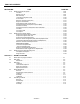
TABLE OF CONTENTS SECTION NO. TITLE PAGE NO. SECTION A - INTRODUCTION - MAINTENANCE SAFETY PRECAUTIONS A B C General . . . . . . . . . . . . . . . . . . . . . . . . . . . . . . . . . . . . . . . . . . . . . . . . . . . . . . . . . . . . . . . . . . . . . .1-1 Hydraulic System Safety . . . . . . . . . . . . . . . . . . . . . . . . . . . . . . . . . . . . . . . . . . . . . . . . . . . . . . . . .1-1 Maintenance . . . . . . . . . . . . . . . . . . . . . . . . . . . . . . . . . . . . . . . . . . . . . . . .
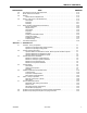
TABLE OF CONTENTS SECTION NO. 2.3 2.4 2.5 2.6 TITLE PAGE NO. Lubrication and Servicing . . . . . . . . . . . . . . . . . . . . . . . . . . . . . . . . . . . . . . . . . . . . . . . . . . . 2-3 Lubrication and Information . . . . . . . . . . . . . . . . . . . . . . . . . . . . . . . . . . . . . . . . . . . . . . . . . . . . . .2-3 Hydraulic System. . . . . . . . . . . . . . . . . . . . . . . . . . . . . . . . . . . . . . . . . . . . . . . . . . . . . . . . . . 2-3 Hydraulic Oil . . . . . . . . . . . . .
TABLE OF CONTENTS SECTION NO. 3.7 3.8 3.9 3.10 3.11 3.12 3.13 3.14 3.15 3.16 3.17 3.18 3121202 TITLE PAGE NO. Swing Hub . . . . . . . . . . . . . . . . . . . . . . . . . . . . . . . . . . . . . . . . . . . . . . . . . . . . . . . . . . . . . . . . . . . .3-36 Adjustment Procedures . . . . . . . . . . . . . . . . . . . . . . . . . . . . . . . . . . . . . . . . . . . . . . . . . . . . . 3-36 Disassembly. . . . . . . . . . . . . . . . . . . . . . . . . . . . . . . . . . . . . . . . . . . . . . . . .
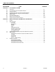
TABLE OF CONTENTS SECTION NO. 3.19 3.20 3.21 TITLE PAGE NO. GM Engine Dual Fuel System . . . . . . . . . . . . . . . . . . . . . . . . . . . . . . . . . . . . . . . . . . . . . . . . . . . . .3-98 Fuel Filter . . . . . . . . . . . . . . . . . . . . . . . . . . . . . . . . . . . . . . . . . . . . . . . . . . . . . . . . . . . . . . . . 3-99 Electric Lock Off. . . . . . . . . . . . . . . . . . . . . . . . . . . . . . . . . . . . . . . . . . . . . . . . . . . . . . . . . . . 3-99 EPR Assembly . . . . . .
TABLE OF CONTENTS SECTION NO. 4.6 4.7 4.8 4.9 4.10 4.11 TITLE PAGE NO. Limit Switches and Cam Valve Adjustment . . . . . . . . . . . . . . . . . . . . . . . . . . . . . . . . . . . . . . . . . .4-16 Boom Cleanliness Guidelines . . . . . . . . . . . . . . . . . . . . . . . . . . . . . . . . . . . . . . . . . . . . . . . . . . . . .4-16 Platform . . . . . . . . . . . . . . . . . . . . . . . . . . . . . . . . . . . . . . . . . . . . . . . . . . . . . . . . . . . . . . . . . . . . . .
TABLE OF CONTENTS SECTION NO. TITLE PAGE NO. SECTION 6 - JLG CONTROL SYSTEM 6.1 6.2 6.3 6.4 6.5 6.6 6.7 6.8 6.9 Introduction . . . . . . . . . . . . . . . . . . . . . . . . . . . . . . . . . . . . . . . . . . . . . . . . . . . . . . . . . . . . . . . . . . .6-1 To Connect the JLG Control System Analyzer . . . . . . . . . . . . . . . . . . . . . . . . . . . . . . . . . . . . . . . .6-3 Using the Analyzer . . . . . . . . . . . . . . . . . . . . . . . . . . . . . . . . . . . . . . . . . . . . . . . . . . .
LIST OF FIGURES FIGURE NO. 1-1. 1-2. 1-3. 1-4. 1-5. 1-6. 1-7. 1-8. 1-9. 2-1. 2-2. 2-3. 2-4. 3-1. 3-2. 3-3. 3-4. 3-5. 3-6. 3-7. 3-8. 3-9. 3-10. 3-11. 3-12. 3-13. 3-14. 3-15. 3-16. 3-17. 3-18. 3-19. 3-20. 3-21. 3-22. 3-23. 3-24. 3-25. 3-26. 3-27. 3-28. 3-29. 3-30. 3121202 TITLE PAGE NO. Lubrication and Operator Maintenance Point Location . . . . . . . . . . . . . . . . . . . . . . . . . . . . . . . . .1-9 Filter Lock Assembly . . . . . . . . . . . . . . . . . . . . . . . . . . . . . . . . . . . . . . . .
LIST OF FIGURES FIGURE NO. 3-31. 3-32. 3-33. 3-34. 3-35. 3-36. 3-37. 3-38. 3-39. 3-40. 3-41. 3-42. 3-43. 3-44. 3-45. 3-46. 3-47. 3-48. 3-49. 3-50. 3-51. 3-52. 3-53. 3-54. 3-55. 3-56. 3-57. 3-58. 3-59. 3-60. 3-61. 3-62. 3-63. 3-64. 3-65. 3-66. 3-67. 3-68. 3-69. 3-70. 3-71. 3-72. 3-73. 3-74. 3-75. 3-76. viii TITLE PAGE NO. Shaft and Front Bearing . . . . . . . . . . . . . . . . . . . . . . . . . . . . . . . . . . . . . . . . . . . . . . . . . . . . . . . . .3-30 Cylinder Kit Installation . . . . . . . .
LIST OF FIGURES FIGURE NO. 3-77. 3-78. 3-79. 3-80. 3-81. 3-82. 3-83. 3-84. 3-85. 3-86. 3-87. 3-88. 3-89. 4-1. 4-2. 4-3. 4-4. 4-5. 4-6. 4-7. 4-8. 4-9. 4-10. 4-11. 4-12. 4-13. 4-14. 4-15. 4-16. 4-17. 4-18. 4-19. 4-20. 4-21. 4-23. 4-24. 4-25. 4-22. 4-26. 4-27. 4-28. 4-29. 4-30. 4-31. 4-32. 4-33. 3121202 TITLE PAGE NO. Low Pressure Regulators . . . . . . . . . . . . . . . . . . . . . . . . . . . . . . . . . . . . . . . . . . . . . . . . . . . . . . . .3-100 Air Fuel Mixer. . . . . . . . . . . . . . . . . .
LIST OF FIGURES FIGURE NO. 5-1. 5-2. 5-3. 5-4. 5-5. 5-6. 5-7. 5-8. 5-9. 5-10. 5-11. 5-12. 5-13. 5-14. 5-15. 5-16. 5-17. 5-18. 5-19. 5-20. 5-21. 5-22. 5-23. 5-24. 5-25. 5-26. 5-27. 5-28. 5-29. 5-30. 5-31. 6-1. 6-2. 6-3. 6-4. 6-5. 6-6. 6-7. 6-8. 6-9. 6-10. 6-11. 6-12. x TITLE PAGE NO. Boom Positioning and Support, Cylinder Repair . . . . . . . . . . . . . . . . . . . . . . . . . . . . . . . . . . . . . .5-3 Cylinder Barrel Support. . . . . . . . . . . . . . . . . . . . . . . . . . . . . . . . . . . . . .
LIST OF FIGURES FIGURE NO. 7-1. 7-2. 7-3. 7-4. 7-5. 7-6. 7-7. 7-8. 7-9. 7-10. 7-11. 7-12. 7-13. 7-14. 7-15. 7-16. 7-17. 7-18. 7-19. 7-20. 7-21. 7-22. 7-23. 7-24. 7-25. 7-26. 7-27. 7-28. 7-29. 7-30. 7-31. 7-32. 7-33. 3121202 TITLE PAGE NO. Voltage Measurement (DC). . . . . . . . . . . . . . . . . . . . . . . . . . . . . . . . . . . . . . . . . . . . . . . . . . . . . . .7-1 Resistance Measurement . . . . . . . . . . . . . . . . . . . . . . . . . . . . . . . . . . . . . . . . . . . . . . . . . . . . . .
LIST OF TABLES TABLE NO. 1-1 1-2 1-3 1-4 1-5 1-6 1-7 1-8 1-9 1-10 1-11 1-12 1-13 1-14 1-15 1-16 1-17 1-18 1-19 1-20 1-21 1-22 1-23 1-24 1-25 1-26 1-27 1-28 1-29 1-30 2-1 2-2 2-3 3-1 3-2 3-3 3-4 3-5 3-6 3-7 3-8 3-9 3-10 3-11 3-12 3-13 4-1 5-1 5-2 6-1 6-2 6-3 6-4 6-5 6-6 6-7 6-8 xii TITLE PAGE NO. Capacities . . . . . . . . . . . . . . . . . . . . . . . . . . . . . . . . . . . . . . . . . . . . . . . . . . . . . . . . . . . . . . . . . . . .1-1 Ford LRG-425 Specifications . . . . . . . . . . . . . . . .
SECTION 1 - SPECIFICATIONS SECTION 1. SPECIFICATIONS 1.1 CAPACITIES Table 1-3. Deutz F4M1011F/F4M2011 Specifications Fuel Table 1-1. Capacities Diesel Fuel Tank 39 Gallons (147.6 L) Hydraulic Oil Tank 31 Gallons (117.3 L) w/ 10% air space Oil Capacity Cooling System Crankcase Total Capacity Hydraulic System (Including Tank) 37.2 Gallons (140.8 L) Idle RPM 1000 Low RPM 1800 Torque Hub, Drive* 17 ounces (0.
SECTION 1 - SPECIFICATIONS Swing System Table 1-6. GM 3.0L Fuel Gasoline or Gasoline/LP Gas No. of Cylinders Table 1-9. Swing System Specifications 4 BHP Gasoline LP 83 hp @ 3000 rpm 75 hp @ 3000 rpm Bore 4.0 in. (101.6 mm) Stroke 3.6 in. (91.44 mm) Displacement 181 cu.in. (3.0 L, 2966 cc) Oil Capacity w/filter 4.5 qts. (4.25 L) Minimum Oil Pressure at idle Hot 6 psi (0.4 Bar) @ 1000 rpm 18 psi (1.2 Bar) @ 2000 rpm Compression Ratio 9.2:1 Firing Order 1-3-4-2 Max.
SECTION 1 - SPECIFICATIONS 1.3 PERFORMANCE DATA Dimensional Data Table 1-14. Dimensional Data Table 1-12. Performance Data Travel Speed 2WD 4WD 4.5 MPH (7.25 Km/hr.) 4 MPH (6.44 Km/hr.) Gradeability 2WD 4WD 30% 45% Machine Weight (Approximate) Table 1-13. Machine Weight (Approximate) Model Lbs.
SECTION 1 - SPECIFICATIONS 1.4 FUNCTION SPEEDS Test Notes 1. Stop watch should be started with the function, not with the controller or switch. Machine Orientation When Doing Speed Tests 2. All speed tests are run from the platform. These speeds do not reflect the ground control operation. Lift: Telescope Retracted. Lift Up, Record Time, Lift Down, Record Time. 3. The platform speed knob control must be at full speed (turned clockwise completely). Swing: Boom at Full Elevation. Telescope Retracted.
SECTION 1 - SPECIFICATIONS 1.5 TORQUE REQUIREMENTS When Outside Temperature is Consistently Use SAE Viscosity Number Below +10°F. (+12°C.) *5W-20 Below +60°F. (+16°C.) 5W-30 -10°F. to +90°F. (-23°C. to +32°C.) 10W-30 Above -10°F. (-23°C.) 10W-40 or 10W-50 Above +20°F. (+7°C.) 20W-40 or 20W-50 Table 1-16. Torque Requirements Torque Value (Dry) Interval Hours 190 ft. lbs. (258 Nm) See Note 50/600* 190 ft. lbs. (258 Nm) See Note 50/600* Wire Rope 15 ft.
SECTION 1 - SPECIFICATIONS Hydraulic Oil Table 1-19. Mobil DTE 13M Specs Table 1-17. Hydraulic Oil HYDRAULIC SYSTEM OPERATING TEMPERATURE RANGE ISO Viscosity Grade SAE VISCOSITY GRADE +0° to +180° F (-18° C to +83° C) 10W +0° F to +210° F (-18° C to +99° C) 10W-20, 10W-30 +50° F to +210° F (+10° C to +210° C) Gravity, API 29.0 Density, Lb/Gal. 60°F 7.35 Pour Point, Max -46°F (-43°C) Flash Point, Min.
SECTION 1 - SPECIFICATIONS 1.8 CYLINDER SPECIFICATIONS Table 1-23. Cylinder Specifications - 660SJ DESCRIPTION Table 1-21. Cylinder Specifications- 600S DESCRIPTION BORE STROKE ROD DIA. Lift 6.00 (152.4) 44.6875 (1135.1) 3 (76.2) Telescope 3.5 (88.9) 177.75 (4514.9) 2.5 (63.5) Steer 2.5 (63.5) 10.75 (273.1) 1.25 (31.8) Lockout (2wd) 4 (101.6) 3.875 (98.4) 1.5 (38.1) Master 3 (76.2) 8.5 (215.9) 1.5 (38.1) Slave Level 3 (76.2) 8.5 (215.9) 1.5 (38.1) Table 1-22.
SECTION 1 - SPECIFICATIONS Table 1-27. Critical Stability Weights - 600S Table 1-25. Major Component Weights - 600SJ LB. KG. Size (15 - 19.5) 253 115 Ford 460 209 1580 Deutz 534 242 7915 3590 Continental 558 253 Chassis Complete (w/pneumatic tires) 11300 5126 Counterweight Weight 2900 1315 Chassis Complete (w/foam-filled tires) 12580 5707 Platform 6 ft. (1.83 M) 205 93 Machine Complete (GVW) - 2WD w/pneumatic tires 23500 10660 8 ft. (2.
SECTION 1 - SPECIFICATIONS Figure 1-1. Lubrication and Operator Maintenance Point Location 1.11 LUBRICATION AND OPERATOR MAINTENANCE NOTE: The following numbers correspond to those in Figure 1-1., Lubrication and Operator Maintenance Point Location. LUBRICATION INTERVALS ARE BASED ON MACHINE OPERATION UNDER NORMAL CONDITIONS. FOR MACHINES USED IN MULTISHIFT OPERATIONS AND/OR EXPOSED TO HOSTILE ENVIRONMENTS OR CONDITIONS, LUBRICATION FREQUENCIES MUST BE INCREASED ACCORDINGLY. Table 1-30.
SECTION 1 - SPECIFICATIONS 4. Wheel Drive Hub 2. Wheel Bearings Lube Point(s) - Repack Capacity - A/R Lube - MPG Interval - Every 2 years or 1200 hours of operation 3. Swing Drive Hub Lube Point(s) - Level/Fill Plug Capacity - 17 oz. (1/2 Full) Lube - EPGL Interval - Check level every 3 months or 150 hrs of operation; change every 2 years or 1200 hours of operation 5. Hydraulic Return Filter Lube Point(s) - Level/Fill Plug Capacity - 17 oz.
SECTION 1 - SPECIFICATIONS 7. Hydraulic Tank 9. Oil Change w/Filter - Ford LRG425 NORMAL OPERATING RANGE WITH BOOM IN STOWED POSITION Lube Point(s) - Fill Cap/Spin-on Element Capacity - 4.5 Quarts Lube - EO Interval - 3 Months or 150 hours of operation Comments - Check level daily/Change in accordance with engine manual. Lube Point(s) - Fill Cap Capacity - 30.6 gal. Tank; 32.7 gal. System Lube - HO Interval - Check Level daily; Change every 2 years or 1200 hours of operation. 8.
SECTION 1 - SPECIFICATIONS 12. Oil Change w/Filter - GM 14. Fuel Filter - Deutz Lube Point(s) - Fill Cap/Spin-on Element Capacity - 4.5 qt. (4.25 L) w/filter Lube - EO Interval - 3 Months or 150 hours of operation Comments - Check level daily/Change in accordance with engine manual. 13. Fuel Filter - Ford Lube Point(s) - Replaceable Element Interval - Every Year or 600 hours of operation 15. Fuel Filter - Caterpillar Lube Point(s) - Replaceable Element Interval - Every Year or 600 hours of operation 16.
SECTION 1 - SPECIFICATIONS Draining Oil Build Up From The Propane Regulator 18. Electronic Pressure Regulator (LP only) During the course of normal operation oils may build inside the primary and secondary chambers of the propane pressure regulator. These oils may be a result of poor fuel quality, contamination of the fuel supply chain, or regional variation in the make up of the fuel. If the build up of the oil is significant this can effect the operation of the fuel control system. Refer to Section 1.
SECTION 1 - SPECIFICATIONS 6. Remove the retainer clip for the LPG fuel temperature sensor and remove the sensor from the regulator body. NOTE: Propane Fuel Filter Replacement Have a small container ready to collect oil that will drain freely from the regulator at this point. 1. 2. 3. 4. 5. 6. 7. Once all of the oil has been drained, reinstall the LPG fuel temperature sensor and reconnect the electrical connector. 8. Open the fuel tank manual valve. 9.
SECTION 1 - SPECIFICATIONS Propane Fuel System Pressure Relief INSTALLATION BE SURE TO REINSTALL THE FILTER MAGNET INTO THE HOUSING BEFORE INSTALLING NEW SEAL 1. Install the mounting plate to lock off O-ring seal. 2. Install the retaining bolt seal. THE PROPANE FUEL SYSTEM OPERATES AT PRESSURES UP TO 312 PSI (21.5 BAR). TO MINIMIZE THE RISK OF FIRE AND PERSONAL INJURY, RELIEVE THE PROPANE FUEL SYSTEM PRESSURE (WHERE APPLICABLE) BEFORE SERVICING THE PROPANE FUEL SYSTEM COMPONENTS. 3.
SECTION 1 - SPECIFICATIONS Figure 1-4.
SECTION 1 - SPECIFICATIONS Figure 1-5.
SECTION 1 - SPECIFICATIONS Figure 1-6.
SECTION 1 - SPECIFICATIONS Figure 1-7.
SECTION 1 - SPECIFICATIONS Figure 1-8.
SECTION 1 - SPECIFICATIONS Figure 1-9.
SECTION 1 - SPECIFICATIONS NOTES: 1-22 – JLG Lift – 3121202
SECTION 2 - GENERAL SECTION 2. GENERAL 2.1 MACHINE PREPARATION, INSPECTION, AND MAINTENANCE General This section provides the necessary information needed by those personnel that are responsible to place the machine in operation readiness and maintain its safe operating condition. For maximum service life and safe operation, ensure that all the necessary inspections and maintenance have been completed before placing the machine into service.
SECTION 2 - GENERAL Table 2-1. Inspection and Maintenance Primary Responsibility Service Qualification Reference Prior to use each day; or At each Operator change. User or Operator User or Operator Operation and Safety Manual Pre-Delivery Inspection Prior to each sale, lease, or rental delivery. Owner, Dealer, or User Qualified JLG Mechanic Service and Maintenance Manual and applicable JLG inspection form.
SECTION 2 - GENERAL Component Disassembly and Reassembly When disassembling or reassembling a component, complete the procedural steps in sequence. Do not partially disassemble or assemble one part, then start on another. Always recheck your work to assure that nothing has been overlooked. Do not make any adjustments, other than those recommended, without obtaining proper approval.
SECTION 2 - GENERAL 2. The design and manufacturing tolerances of the component working parts are very close, therefore, even the smallest amount of dirt or foreign matter entering a system can cause wear or damage to the components and generally results in faulty operation. Every precaution must be taken to keep hydraulic oil clean, including reserve oil in storage.
SECTION 2 - GENERAL Cylinder Drift 4. Re-assembly of pinned joints using filament wound bearings. Table 2-2. Cylinder Drift Cylinder Bore Diameter a. Housing should be blown out to remove all dirt and debris...bearings and bearing housings must be free of all contamination. Max. Acceptable Drift in 10 Minutes inches mm inches mm 3 76.2 0.026 0.66 3.5 89 0.019 0.48 4 101.6 0.015 0.38 5 127 0.009 0.22 6 152.4 0.006 0.15 7 177.8 0.005 0.13 8 203.2 0.0038 0.10 9 228.6 0.
SECTION 2 - GENERAL Table 2-3.
SECTION 2 - GENERAL Table 2-3.
SECTION 2 - GENERAL Table 2-3.
SECTION 2 - GENERAL 4150548 E Figure 2-1.
SECTION 2 - GENERAL 4150548 E Figure 2-2.
SECTION 2 - GENERAL 4150548 E Figure 2-3.
SECTION 2 - GENERAL 4150548 E Figure 2-4.
SECTION 3 - CHASSIS & TURNTABLE SECTION 3. CHASSIS & TURNTABLE 3.1 TIRES & WHEELS tire brands, both tires on the same axle should be the same. Tire Inflation The air pressure for pneumatic tires must be equal to the air pressure that is stenciled on the side of the JLG product or rim decal for safe and proper operational characteristics. Tire Damage For pneumatic tires, JLG Industries, Inc.
SECTION 3 - CHASSIS & TURNTABLE 3.2 DRIVE TORQUE HUB Roll, Leak and Brake Testing 10 LUG PATTERN Torque-Hub units should always be roll and leak tested before disassembly and after assembly to make sure that the unit's gears, bearings and seals are working properly. The following information briefly outlines what to look for when performing these tests. NOTE: The brake must be released before performing the roll test.
SECTION 3 - CHASSIS & TURNTABLE Reference: Sample Model 7HBE01F0B30057. The underlined letter is the brake option. Options are A, B, C, D, E, or X. A Input Brake 2,200 in-lb (248 Nm) Static, 280 psi (19.3 bar) Full Release 3000 psi (207 bar) maximum o-ring check. B Input Brake 1,900 in-lb (215 Nm) Static, 240 psi (16.5 bar) Full Release 3000 psi (207 bar) maximum o-ring check. C Input Brake 1,600 in-lb (181 Nm) Static, 200 psi (13.8 bar) Full Release 3000 psi (207 bar) maximum o-ring check.
SECTION 3 - CHASSIS & TURNTABLE 6. Cover 6G. Retaining Ring 15. ID Plate Figure 3-1.
SECTION 3 - CHASSIS & TURNTABLE 1A. Spindle 1D. Housing 1E. Ring Gear 3. Input Carrier 4. Planet Gear 4E. Planet Shaft 4G. Roll Pin 4H. Thrust Washer 5. Retaining Ring 9. Input Shaft 10. First Stage Sun Gear 11. Second Stage Sun Gear 18. O-ring 19. Bolt 20. Retaining Ring Figure 3-2. Input Carrier 5. Remove the First Stage Sun Gear (10) if applicable.
SECTION 3 - CHASSIS & TURNTABLE 15. Slide the Planet Gear Subassembly (4) out of the Spindle (1A) being careful to not drop the Needle Bearings (4C) in the process. 16. Remove 4 Thrust Washers (4B), 28 Needle Rollers (4C) and the Thrust Spacer (4D) from the Second Stage Planet Gear (4F). 4B. Thrust Washer 4C. Needle Roller 17. Repeat Steps 12 though 16 for the remaining two Planet Gears (4F). 18. Remove the Thrust Washer (4H) from the counterbore in the Spindle (1A). 4D. Thrust Spacer 4F.
SECTION 3 - CHASSIS & TURNTABLE Input Carrier Disassembly 3C. Needle Bearing 3F. Planet Gear Figure 3-5. Planet Gear Subassembly 1. Using a 1/8” diameter punch, drive the Roll Pin (4G) into the Planet Shaft (3E) until it bottoms against the Carrier (3A). 3A. Carrier 3B. Thrust Washer 3E. Planet Shaft 2. Using a soft face hammer, tap the Planet Shaft (3E) out of the Carrier (3A). 3F. Planet Gear 4G. Roll Pin Figure 3-4. Input Carrier 3.
SECTION 3 - CHASSIS & TURNTABLE Hub-Spindle Disassembly 1A. Barrel 1B. Seal 1C. Bearing Cone 1D. Hub 1F. Bearing Nut 1G. Setscrew 1H. Stud 1Q. Boot Seal Figure 3-6. Hub Spindle 6. If necessary, press 9 Studs (1H) out of Hub (1D). Locate Hub (1D) on Seal (1B) end. 1. Place unit on bench with Spindle (1A) end down. 2. Remove 2 Set Screws (1G) and Bearing Nut (1F) using T-206569. NOTE: The holes in the Bearing Nut (1F) for the Set Screws (1G) were staked for retention of the Set Screws (1G).
SECTION 3 - CHASSIS & TURNTABLE Spindle-Brake Disassembly 1A. Spindle 7. Coupling Subassembly 8A. Piston 8B. Pressure Plate 8C. Retaining Ring 8D. O-Ring 8E. Backup Ring 8F. O-Ring 8H. Backup Ring 8J. Rotor 8K. Stator 8L. Compression Spring 12. Plastic Plug 21. Pipe Plug 22. Flat Head Capscrew Figure 3-7.
SECTION 3 - CHASSIS & TURNTABLE 2. Using retaining ring pliers, remove Retaining Ring (8C) from the groove in the Spindle (1A). 3. Back Flat Head Cap Screws (22) incrementally out of Piston (8A) until spring force is relieved from the Pressure Plate (8B). Then, remove Flat Head Cap Screws (22) and Pressure Plate (8B) from brake cavity in Spindle (1A). 4. Remove Compression Springs (8L) from Piston (8A). EYE PROTECTION MUST BE WORN WHILE PERFORMING THE NEXT STEP IN THIS PROCEDURE. 5.
SECTION 3 - CHASSIS & TURNTABLE Cover Disassembly 2. Thrust Washer 6A. Cover 6B. Disengage Cap 6C. Bolt 6D. Disengage Rod 6E. O-Ring 6F. Pipe Plug 17. O-Ring Figure 3-9. Cover 1. Remove O-Ring (17) from groove in Cover (6A). 2. Remove Thrust Washer (2) from Cover (6A) pockets. 3. Unscrew two Hex Head Bolts (6C) and remove Disengage Cap (6B) from Cover (6A). 5. Use appropriate tool to remove O-ring (6E) from internal groove in Cover (6A). 6. Remove two O-Ring Pipe Plugs (6F) from Cover (6A). 4.
SECTION 3 - CHASSIS & TURNTABLE Input Carrier Sub-Assembly Output Planet Gear Sub-Assembly 1. Apply a liberal coat of grease to the bore of one Input Planet Gear (3F). 1. Apply a liberal coat of grease to the bore of one Output Planet Gear (4F). 2. Line the inside of the Planet Gear (3F) with 14 Needle Rollers (3C). 2. Line the inside of the Planet Gear (4F) with 14 Needle Rollers (4C). NOTE: The last roller installed must be installed end wise.
SECTION 3 - CHASSIS & TURNTABLE 9. Install small Backup Ring (8H) in the small-diameter groove near the top of the Piston (8A), on top of the small O-Ring (8F). 7. Install Bearing Cone of part (1C) into Bearing Cup, position "A". 8. Apply Loctite 243 on Bearing Nut (1F) thread. Screw Nut (1F) on top of Bearing Cone of part (1C). Leave 0.003-0.005 inches end play to check the initial rolling torque with the unit tied down.
SECTION 3 - CHASSIS & TURNTABLE Cover Sub-Assembly 1. Grease O-Ring (6E) and insert into internal groove in Cover (6A). 2. Assemble Disengage Cap (6B) onto Cover (6A) using two Hex Head Bolts (6C). Torque bolts to 7080 in-lbs. 3. Insert Disengage Rod (6D) into hole in Cover (6A) until it touches the inside of the Disengage Cap (6B). 11. Install Cover Sub-Assembly (6) into Ring Gear (1E) counterbore and install Retaining Ring (6G) into groove in Ring Gear (1E). 12.
SECTION 3 - CHASSIS & TURNTABLE 1A. Spindle 1B. Lip Seal 1C. Tapered Bearing 1D. Housing 1E. Ring Gear 1F. Bearing Nut 1G. Setscrew 1H. Stud 1K. Retaining Ring 1L. Spring 1M. Thrust Washer 1Q. Seal Boot 2. Thrust Spacer 3A. Carrier 3B. Thrust Washer 3C. Needle Bearing 3E. Planet Shaft 3F. Planet Gear 4B. Thrust Washer 4C. Needle Bearing 4D. Thrust Spacer 4E. Planet Shaft 4F. Planet Gear 4G. Roll Pin 4H. Thrust Washer 5. Retaining Ring 6A. Cover 6B. Disengage Cap 6C. Bolt 6D. Dowel Pin 6E. O-Ring 6F.
SECTION 3 - CHASSIS & TURNTABLE Figure 3-11. Bearing Cup Pressing Tool Figure 3-12.
SECTION 3 - CHASSIS & TURNTABLE Figure 3-13. Bearing Cup Pressing Tool Figure 3-14.
SECTION 3 - CHASSIS & TURNTABLE 3.3 FREE WHEELING OPTION 3.4 DRIVE MOTOR (S/N 75606 TO PRESENT) To Disengage Drive Motors and Brakes (Free Wheel) for Towing, etc. Description 1. Chock wheels securely if not on flat level surface. 2. Disconnect both drive hubs by inverting disconnect caps in center of hubs. 3. If equipped, move steer/tow selector valve to float (tow) position by pulling valve knob out.
SECTION 3 - CHASSIS & TURNTABLE Shaft Seal Replacement INSPECT THE COMPONENTS REMOVAL 1. Remove the snap ring (1) retaining the shaft seal and support washer. Inspect the new seal, the motor housing seal bore, and the sealing area on the shaft for rust, wear, and contamination. Polish the shaft and clean the housing if necessary. INSTALLATION 1 1. Cover the shaft splines with an installation sleeve to protect the shaft seal during installation. 2 2.
SECTION 3 - CHASSIS & TURNTABLE Loop Flushing Valve INSPECT THE COMPONENTS Inspect new O-rings and the sealing area for rust, wear, or contamination. Also check springs and poppet for wear. REMOVAL 1. Using a 11/16 in internal hex wrench remove plug (1) and (2). INSTALLATION 6 2. Install shift spool (12). 9 11 1. Install orifice poppet (13). 2 11/16 in 3. Install spring retaining washers onto springs (10 and 11). 27 ft.lbs. (37 Nm) 4. Carefully install centering springs (7, 8, and 9). 5.
SECTION 3 - CHASSIS & TURNTABLE Troubleshooting Table 3-3. Excessive Noise and/or Vibration Item Description Action Check oil level in reservoir and oil supply to the motor. Fill the reservoir to the proper level and ensure that oil supply Insufficient hydraulic fluid could lead to cavitation that would to the motor is adequate and the lines are unobstructed. cause system noise. Check for air in the system.
SECTION 3 - CHASSIS & TURNTABLE Disassembly 17 NOTE: Removal of the endcap voids warranty. 19 During assembly, coat all moving parts with a film of clean hydraulic oil. This assures that these parts will be lubricated during start-up. 15 Replace all O-Rings and gaskets. It is recommended that all O-rings be replaced. Lightly lubricate all O-rings with clean petroleum jelly prior to assembly. 14 6 21 9 11 5 7 2 13 18 3 10 8 4 12 16 16 1 20 14. 15. 16. 17. 1. 2. 3. 4.
SECTION 3 - CHASSIS & TURNTABLE 25 22 27 30 29 23 26 24 29 28 22. Screw 23. End Cap 24. O-ring 25. 26. 27. 28. 29. 30. Figure 3-21. End Cap 13. Using an 8 mm internal hex wrench, remove the endcap screws (22). Valve Plate End Cap O-ring O-ring Angle Stop Servo Spring Figure 3-22. Valve Plate & Rear Shaft Bearing 14. Remove the endcap (23). Remove O-ring (24) from the housing or endcap.
SECTION 3 - CHASSIS & TURNTABLE 18. Remove minimum angle stop (29) and servo spring (30) from the housing. 20. Turn the housing over and remove the snap ring (32) retaining the shaft seal and support washer. Remove the support washer (33) and carefully pry out the shaft seal (34). Discard the seal. To avoid damaging the shaft during seal removal. Install a large sheet metal screw into the chuck of a slide hammer. Drive the screw into the seal surface and use the slide hammer to pull the seal.
SECTION 3 - CHASSIS & TURNTABLE Lift here 44 39 45 47 40 48 43 42 49 41 46 53 52 39. 40. 41. 42. 43. Swashplate Servo Piston Piston Seal O-ring Journal Bearings 50 51 Figure 3-26. Swash Plate & Servo Piston 44. 45. 46. 47. 48. 23. Turn housing over and remove the swashplate (39) by lifting on the end opposite the servo lever. 24. Remove the servo piston (40). Remove the piston seal (41) and O-ring (42) from the servo piston. Discard the seal and O-ring. 25.
SECTION 3 - CHASSIS & TURNTABLE SLIPPERS 28. Turn the block over. Using a press, apply pressure on the block spring washer (50) to compress the block spring. Compress the spring enough to safely remove the spiral retaining ring (51). While maintaining pressure, unwind the spiral retaining ring (51). Carefully release the pressure and remove the outer block spring washer (50), block spring (52), and inner block spring washer (53) from the cylinder block. Inspect the running surface of the slippers.
SECTION 3 - CHASSIS & TURNTABLE BALL GUIDE AND SLIPPER RETAINER Inspect the ball guide and slipper retainer for damage, discoloration, or excessive wear. A discolored ball guide or slipper retainer indicates excessive heat. Do not reuse. Replace swashplate if the difference in thickness from one side to the other exceeds specification. 0.0025 mm [0.0001 in] Slipper retainer 25.8 mm LV [1.015 in] mm KV 24.6 [0.969 in] Ball guide Thickness equality side to side: 0.05 mm [0.
SECTION 3 - CHASSIS & TURNTABLE SERVO PISTON AND MINIMUM ANGLE STOP Inspect the minimum angle stop, servo piston head, and servo piston ball-socket for damage or excessive wear. Replace if necessary. Assembly 1. Install new O-ring (1) and piston seal (2) to the servo piston (3). Install the piston seal over the O-ring. Installing the piston seal stretches it, making it difficult to install the servo piston in its bore. Allow 30 minutes for the seal to relax after installation.
SECTION 3 - CHASSIS & TURNTABLE block. Using a press, compress the block spring enough to expose the retaining ring groove. Wind the spiral retaining ring (7) into the groove in the cylinder block. 11 6. Install the journal bearings (13) into the housing seats. Use assembly grease to keep the bearings seated during assembly. Ensure the locating nubs drop into the cavities in the seats. If you're reusing the bearings, install them in the original location and orientation. Lubricate the journal bearings.
SECTION 3 - CHASSIS & TURNTABLE 8. Press front shaft bearing (15) onto shaft (16). Press bearing onto shaft with lettering facing out. Lubricate bearing rollers. Install snap-ring (17) onto shaft. 10. Verify swashplate and bearings are properly seated. Install the cylinder kit (19) onto the shaft. Install with the slippers facing the swashplate. Rock the shaft to align the block splines and slide the cylinder kit into place.
SECTION 3 - CHASSIS & TURNTABLE 12. Press the rear shaft bearing (22) into the endcap. Install the bearing with letters facing out. Press until bearing surface is 0.08 ±0.01 in (2 ±0.25 mm) above endcap surface. 22 2 mm [0.08 in] 23 3 mm [0.12 in] 15. Install the endcap (25) onto the housing with the endcap screws (26). Check to ensure the endcap will properly seat onto the housing without interference. Improper assembly of the internal components may prevent the endcap from seating properly.
SECTION 3 - CHASSIS & TURNTABLE 18. Cover shaft splines with an installation sleeve. Install a new shaft seal (27) with the cup side facing the motor. Press seal into housing until it bottoms out. Press evenly to avoid binding and damaging the seal. Install seal support washer (28) and snap ring (29). 19. Install remaining plugs and fittings to the housing. Refer to the drawing below for wrench sizes and installation torques. 5/16 in 63 ft.lbs. (85 Nm) 1/4 in 33 ft.lbs.
SECTION 3 - CHASSIS & TURNTABLE Initial Start-up Procedures 20. Install orifice poppet (30). Follow this procedure when starting-up a new motor or when installing a motor that has been removed. 37 36 33 39 41 34 11/16 in 30 27 ft.lbs. (37 Nm) 40 5/8 in 20 ft.lbs. (27 Nm) 32 35 38 Prior to installing the motor, inspect for damage incurred during shipping. Make certain all system components (reservoir, hoses, valves, fittings, heat exchanger, etc.) are clean prior to filling with fluid. 1.
SECTION 3 - CHASSIS & TURNTABLE 3.5 OSCILLATING AXLE BLEEDING PROCEDURE AND LOCKOUT TEST 5. Open both bleeder screws (one on each lockout cylinder). Lockout Cylinder Bleeding ENSURE PLATFORM IS FULLY LOWERED AND BOOM IS CENTERED OVER REAR AXLE PRIOR TO BEGINNING BLEEDING PROCEDURE. ENSURE MACHINE IS ON A LEVEL SURFACE AND REAR WHEELS ARE BLOCKED, BRAKE WIRE IS DISCONNECTED. 1. Making sure machine is on a level surface and rear wheels are blocked, brake wire is disconnected. 2.
SECTION 3 - CHASSIS & TURNTABLE 7. Have an assistant check to see that left front wheel remains locked in position off of ground. #2 to contact axle. Steer full right and adjust LH item #2 to contact axle. (2WS/4WD) 8. Carefully activate SWING control lever and return boom to stowed position (centered between drive wheels). When boom reaches center, stowed position, lockout cylinders should release and allow wheel to rest on ground, it may be necessary activate DRIVE to release cylinders. 9.
SECTION 3 - CHASSIS & TURNTABLE Figure 3-40. Swing Torque Hub Adjustment 3.7 SWING HUB 7. Remove the retaining ring (1I) from the output shaft (1A) and discard. Adjustment Procedures NOTE: The swing bearing high spot is usually marked with a colored paint. EYE PROTECTION SHOULD BE WORN DURING RETAINING RING (1I) REMOVAL. 1. Ensure swing drive is located on bearing gear max eccentric tooth (high spot). 8. Remove bearing shim (1H) from the output shaft (1A). 2.
SECTION 3 - CHASSIS & TURNTABLE WHEN REBUILDING OR REPAIRING THE UNIT, THE RETAINING RING (1I), O-RINGS (5) AND SEAL (1B) SHOULD ALWAYS BE REPLACED. 3. Place O-ring (5) into hub counterbore. Use petroleum jelly to hold O-ring in place. Also at this time locate and mark the 4 counter beamed holes in the face of the hub (1G). This is for identification later in the assembly. Main Assembly Procedure 1. With the hub shaft sub-assembly resting on the shaft (1A) install internal gear (2).
SECTION 3 - CHASSIS & TURNTABLE 6. With shoulder side of ring gear (4) facing down, place ring gear over (into mesh with) large gears. Be sure that punch marks remain in correct location during ring gear installation. The side of the ring gear with an x stamped on it should be up. 8. Input gear (8) is installed, meshing with teeth of the large diameter cluster gear (3F). The counterbore on the input gear (8) locates on the shoulder of the thrust spacer (9). This is to be a slip fit and operate freely. 7.
SECTION 3 - CHASSIS & TURNTABLE 14. Pipe plugs (20) are to be installed into cover (6) using a lubricant of some sort. BEWARE OF SHARP EDGES OF THE COUNTERBORE WHILE SEATING THIS O-RING. 15. Torque shoulder bolts (13) to 23-27 ft./lbs. and regular grade 8 bolts (12) to 23-27 ft./lbs, 12. THe cover (6) is now installed on this assembly. Taking care to correctly align pipe plug hole (20) with those in the hub (1J), usually 90° to one another.
SECTION 3 - CHASSIS & TURNTABLE Hub Shaft Sub-Assembly 4. Returning the hub (1G) to locate on the large diameter end, the output shaft (1A) is carefully installed into the hub (1G). 1. Press bearing cone (1D) onto shaft (1A). 2. Press bearing cup (1C) into hub (1G) taking care to insure cup start square with the bore of the hub. 5. The shaft seal (1B) is installed over the output shaft (1A) and into the counterbore of the hub (1G).
SECTION 3 - CHASSIS & TURNTABLE 7. Pipe plugs (1J & 1K) should be checked and/ or installed at this time in the assembly. 10. A soft metal punch should be used to insure that this retaining ring (1I) is completely seated in the groove of the output shaft (1A). EYE PROTECTION SHOULD BE WORN DURING THIS PROCEDURE. 8. Bearing spacer (1H) is installed around the output shaft (1A) and locates on bearing cone (1F). 11.
SECTION 3 - CHASSIS & TURNTABLE Carrier Sub-Assembly 4. Place second set of sixteen needle rollers into cluster gear. 1. Apply a coat of grease or petroleum jelly to cluster gear bore. 5. Apply grease or petroleum jelly to the tang side of two thrust washers. Place thrust washers against bosses in carrier with washer tang fitting into slot in carrier outside diameter. 2. Place sixteen needle rollers into cluster gear bore.
SECTION 3 - CHASSIS & TURNTABLE 6. While keeping thrust washers in place, slide cluster gear into carrier with the larger gear on the side with the small pin hole. 8. Drive anti-roll pin flush into carrier hole, thereby locking planet shaft into place. Repeat these steps for remaining two cluster gears to complete carrier assembly. 7. Line up cluster gear and thrust washer with hole in carrier and slide planet shaft through. Line up chamfered side of hole in planet shaft with pin hole in carrier.
Figure 3-41.
SECTION 3 - CHASSIS & TURNTABLE 3.8 SWING BEARING head and hardened washer at the arrow indicated position. Turntable Bearing Mounting Bolt Condition Check NOTE: This check is designed to replace the existing bearing bolt torque checks on JLG Lifts in service. This check must be performed after the first 50 hours of machine operation and every 600 hours of machine operation thereafter.
Figure 3-43.
SECTION 3 - CHASSIS & TURNTABLE 5. If bearing inspection shows no defects, reassemble and return to service. e. Attach suitable overhead lifting equipment to the base of the turntable weldment. f. Use a suitable tool to scribe a line on the inner race of the swing bearing and on the underside of the turntable. This will aid in aligning the bearing upon installation. Remove the bolts and washers which attach the turntable to the bearing inner race. Discard the bolts.
SECTION 3 - CHASSIS & TURNTABLE Figure 3-45. Swing Bearing Torque Sequence c. Refer to the Torque Sequence diagram as shown in Figure 3-45., Swing Bearing Torque Sequence. Clean any residue off the new bearing bolts, then apply a light coating of Loctite #271 and install the bolts and washers through the frame and outer race of the bearing. Tighten the bolts to a torque of190 ft. lbs. (258 Nm) w/ Loctite. attaching bolts and secure the yoke to the turntable with the mounting hardware. k.
SECTION 3 - CHASSIS & TURNTABLE 3.9 SWING BRAKE - MICO Assembly Disassembly NOTE: Lubricate all seals and o-rings with clean hydraulic oil prior to assembly. 1. With shaft protrusion downward, remove end cover (13) by removing capscrews (12). 1. Press new rotary seal (1) into housing (52). Note the direction of seal. 2. Install new bearing (2) on shaft (51). END COVER IS UNDER SPRING TENSION OF APPROXIMATELY 2000 POUNDS (681 KG). THE FOUR CAPSCREWS SHOULD BE LOOSENED EVENLY TO RELIEVE THIS FORCE.
SECTION 3 - CHASSIS & TURNTABLE Figure 3-46.
SECTION 3 - CHASSIS & TURNTABLE 3.10 ROTARY COUPLING Use the following procedure to install the seal kit. NOTE: Step 1 applies to machines S/N 75606 to Present. 1. If not already removed, remove the axle oscillation valve from the cylinder barrel. The spool of the valve protrudes into the barrel and will damage the spool and seals if left in place. 2. Remove snap ring (12) from end. 3. Remove thrust ring (13) from the same end. 4. Remove center body (10) from housing (11). 5.
SECTION 3 - CHASSIS & TURNTABLE 1. 2. 3. 4. Rotary Coupling Torque Lug Locknut Flatwasher 5. Bolt 6. Nut 7. Bracket Figure 3-47.
SECTION 3 - CHASSIS & TURNTABLE 1. 2. 3. 4. 5. O-ring Plug Check Valve Screw Plug 6. Spring 7. Valve Block Plunger 8. Valve Block 9. O-ring 10. Body 11. 12. 13. 14. 15. Housing Retaining Ring Ring Oil Seal O-ring 16. Bearing 17. Cap Seal 18. O-ring Figure 3-48.
SECTION 3 - CHASSIS & TURNTABLE Figure 3-49.
SECTION 3 - CHASSIS & TURNTABLE Figure 3-50.
SECTION 3 - CHASSIS & TURNTABLE 3.11 GENERATOR Table 3-9. Coupling Port Information Table - 2WS Port Size Operating Pressure PSI (Bar) Proof Pressure PSI (Bar) Port No.
SECTION 3 - CHASSIS & TURNTABLE Overload Protection Inspecting Brushes, Replacing Brushes, and Cleaning Slip Rings STOP THE ENGINE WHENEVER CHECKING OR INSPECTING THE CIRCUIT BREAKER. The circuit breaker protects the generator windings from overload. If the circuit breaker opens, generator output stops. If the circuit breaker continues to open, check for faulty equipment connected to the platform receptacles. Refer to Figure 3-51.
SECTION 3 - CHASSIS & TURNTABLE Brush Position On Slip Rings 2 3 Acceptable Unacceptable Brushes must ride completely on slip rings 1 1/4 in (6 mm) Or Less - Replace 2 7/16 in - 1/2 in (11 - 12 mm) New 3 1. Brush Holder Assembly 2. Brushes 3. Slip Rings Figure 3-51.
SECTION 3 - CHASSIS & TURNTABLE 3.12 SPARK ARRESTER CLEANING INSTRUCTIONS 3.14 FORD EFI ENGINE Performing Diagnostics 1. Remove the cleanout plug in the bottom of spark arrester (muffler). 1. Verify the complaint and determine if it is a deviation from normal operation. 2. Without causing deformation (or any type of damage to the spark arrester) repeatedly tap on the arrester near the cleanout plug. This may be enough to begin drainage of the spark trap. 2.
SECTION 3 - CHASSIS & TURNTABLE ECM/EPM and Sensors VISUAL/PHYSICAL ENGINE INSPECTION CHECK Perform a careful visual and physical engine inspection before performing any diagnostic procedure. Perform all necessary repairs before proceeding with additional diagnosis, this can often lead to repairing a problem without performing unnecessary steps.
SECTION 3 - CHASSIS & TURNTABLE HEATED OXYGEN SENSOR ENGINE COOLANT TEMPERATURE (ECT) SENSOR The engine coolant temperature (ECT) sensor is a g thermistor (a resistor which changes value based on temperature) mounted in the engine coolant stream. Low coolant temperature produces a high resistance of 100,000 ohms at -40°C (-40°F). High temperature causes a low resistance of 70 ohms at 130°C (266°F). The ECM supplies a 5-volt signal to the ECT sensor through resistors in the ECM and measures the voltage.
Figure 3-52.
SECTION 3 - CHASSIS & TURNTABLE INTAKE AIR TEMPERATURE (IAT) SENSOR The intake air temperature (IAT) sensor is a thermistor which changes its resistance based on the temperature of air entering the engine. Low temperature produces a high resistance of 100,000 ohms at -40°C (-40°F). High temperature causes a low resistance of 70 ohms at 130°C (266°F). The ECM supplies a 5-volt signal to the sensor through a resistor in the ECM and monitors the signal voltage.
SECTION 3 - CHASSIS & TURNTABLE The ECM/EPM is designed to maintain exhaust emission levels to government mandated standards while providing excellent operation and fuel efficiency. The ECM/EPM monitors numerous engine functions via electronic sensors such as the throttle position (TP) sensor and the heated oxygen sensor (HO2S). • When measuring voltages, use only a digital voltmeter with an input impedance of at least 10 megohms. • Do not jump start with more than 12 volts.
SECTION 3 - CHASSIS & TURNTABLE ELECTROSTATIC DISCHARGE DAMAGE Electronic components used in the ECM are often designed to carry very low voltage. Electronic components are susceptible to damage caused by electrostatic discharge. Less than 100 volts of static electricity can cause damage to some electronic components. By comparison, It takes as much as 4000 volts for a person to feel the spark of a static discharge. There are several ways for a person to become statically charged.
SECTION 3 - CHASSIS & TURNTABLE HIGH PRESSURE CIRCUIT - OPERATING PRESSURE 65 PSI. Figure 3-53. Typical Fuel System FUEL METERING SYSTEM PURPOSE The basic function of the air/fuel metering system is to control the air/fuel delivery to the engine. Fuel is delivered to the engine by individual fuel injectors mounted in the intake manifold near each intake valve. The ECM/EPM monitors signals from several sensors in order to determine the fuel needs of the engine.
SECTION 3 - CHASSIS & TURNTABLE FUEL PRESSURE REGULATOR The fuel pressure regulator is a relief valve mounted in the fuel filter. It provides a constant fuel pressure of 441 kPa (64 psi). If the pressure is too low, poor performance and a DTC 32 will set. If the pressure is too high, excessive odor and/or a DTC 42 will result. ELECTRONIC GOVERNOR AND THROTTLE BODY In the 2.
SECTION 3 - CHASSIS & TURNTABLE OPEN LOOP AND CLOSED LOOP OPERATION CRANKSHAFT POSITION (CKP) SENSOR The ECM will operate in the following two modes: The crankshaft position (CKP) sensor provides a signal used by the engine control module (ECM) to calculate the ignition sequence. The sensor initiates the reference pulses which the ECM uses to calculate RPM and crankshaft position. • Open loop • Closed loop When the engine is first started, the system is in "open loop" operation.
SECTION 3 - CHASSIS & TURNTABLE IGNITION COIL The electronic ignition system uses a coil pack with one ignition coil for each two cylinders in the engine. Each cylinder is paired with its opposing cylinder in the firing order, so that one cylinder on compression fires simultaneously with the opposing cylinder on exhaust. The spark that occurs in the cylinder on the exhaust stroke is referred to as a "waste spark.
SECTION 3 - CHASSIS & TURNTABLE 3.15 FORD LPG SYSTEM Mixer NOTE: +20° F (-6.6° C) is the low temperature limit for LP gas, for both starting and operation. This applies to all LP gas powered engines. The mixer accepts LPG vapor at the megajector outlet pressure (-1.00 to -5.00 inches [-2.5 to -12.7 cm] of H2O) and mixes it with clean air. This mixture is then sucked into the engine via the actuator. Lockoff Solenoid Description The LPG system starts at the tank.
SECTION 3 - CHASSIS & TURNTABLE Megajector Mixer Regulator Lockoff Solenoid Figure 3-54.
SECTION 3 - CHASSIS & TURNTABLE Megajector Diagnostic Code Descriptions The following diagnostic codes are specific to the megajector. They will be displayed on the analyzer if the JLG Control System senses a fault dealing with the megajector. Refer to Section 6 - JLG Control System for more information concerning the Control System. DTC 354 - Megajector delivery pressure lower than expected.
SECTION 3 - CHASSIS & TURNTABLE Changing from Gasoline to LP Gas DTC 362 - Megajector voltage supply low. a. Voltage - Check battery voltage. If the voltage at the battery is less than 9.5 volts: The battery is faulty IT IS POSSIBLE TO SWITCH FROM ONE FUEL SOURCE TO THE OTHER WITHOUT ALLOWING THE ENGINE TO STOP. EXTREME CARE MUST BE TAKEN AND THE FOLLOWING INSTRUCTIONS MUST BE FOLLOWED. or The charging system is faulty or The Megajector is faulty. 1. Start the engine from the ground control station.
SECTION 3 - CHASSIS & TURNTABLE Figure 3-55.
SECTION 3 - CHASSIS & TURNTABLE 1. 2. 3. 4. Battery Battery Holddown Gear Pump Piston Pump 5. 6. 7. 8. Air Cleaner Fan Motor Mount Muffler 9. 10. 11. 12. Front Right Engine Mounting Plate Front Bottom Engine Mounting Plate Rear Engine Mounting Plate Radiator 13. 14. 15. 16. Starter Relay Aux Pump Relay Restriction Indicator Oil Drain Valve Figure 3-56.
SECTION 3 - CHASSIS & TURNTABLE 17. 18. 19. 20. 21. Engine Tray Engine Mounting Plate Hayes Coupling Pump Adapter Plate Dipstick 22. 23. 24. 25. Filler Cap Oil Lube Pump Oil Filter Injector Pump 26. 27. 28. 29. Fuel Filter Fuel Supply Pump Alternator Starter 30. 31. 32. 33. Temperature Sender Oil Pressure Sensor Speed Sensor Throttle Actuator Figure 3-57.
SECTION 3 - CHASSIS & TURNTABLE 1. 2. 3. 4. 5. 6. 7. Battery Hold-down Battery Air Cleaner Coolant Overflow Container Pump Coupling Fan Engine Mount 8. 9. 10. 11. 12. 13. 14. Muffler Radiator Starter Relay Glow Plug Relay Aux Power Relay Restriction Indicator Oil Drain Valve Figure 3-58.
SECTION 3 - CHASSIS & TURNTABLE 15. 16. 17. 18. 19. 20. 21. Engine Tray Piston Pump Gear Pump Fuel Filter Alternator Oil Pressure Switch Oil Filter 22. 23. 24. 25. 26. 27. Starter Dipstick Engine Temperature Sender Throttle Actuator Fuel Supply Pump Water Pump Figure 3-59.
SECTION 3 - CHASSIS & TURNTABLE 1. 2. 3. 4. Battery Hold-down Battery Piston Pump Load-Sensing Pump 5. 6. 7. 8. Air Cleaner Fan Engine Mount Radiator 9. 10. 11. 12. Aux Power Relay Restriction Indicator Oil Drain Valve Engine Tray 13. 14. 15. 16. Fuel Pump & Isolator Fuel Filter Starter Alternator w/Regulator Figure 3-60.
SECTION 3 - CHASSIS & TURNTABLE 17. 18. 19. 20. Throttle Actuator Air Temperature Sensor MAP Sensor EGR Sensor 21. 22. 23. 24. Dipstick Mixer Assembly Oil Filter Pump Coupling 25. 26. 27. 28. Pressure Regulator EPM Module Muffler LP Regulator 29. EGR Sensor 30. Overflow Bottle 31. Starter Figure 3-61.
SECTION 3 - CHASSIS & TURNTABLE 3.16 DEUTZ EMR 2 (S/N 84827 TO PRESENT) The EMR2 consists of the sensors, the control unit and the actuator. Engine-side controls as well as the JLG Control System are connected by means of separate cable harnesses to the EMR control unit.
SECTION 3 - CHASSIS & TURNTABLE CONTROL ROD POSITION SENSOR/ACTUATOR COOLANT TEMPERATURE SENSOR POWER SUPPLY CAMSHAFT SPEED SENSOR GLOW PLUG JLG SYSTEM HANDLES ENGINE START/ STOP; EMR2 TAKES CONTROL OF THE ENGINE AT 700RPM JLG SYSTEM USES JLG ANALYZER TO REPORT FAULTS DIAGNOSIS INTERFACE/CAN-BUS; JLG SYSTEM USES THIS TO CONTROL THE ENGINE & FAULT REPORTING. OIL PRESSURE SENSOR Figure 3-62.
Figure 3-63.
Figure 3-64.
Figure 3-65.
Figure 3-66.
SECTION 3 - CHASSIS & TURNTABLE Figure 3-67.
SECTION 3 - CHASSIS & TURNTABLE Figure 3-68.
Figure 3-69.
Figure 3-70.
Figure 3-71.
Figure 3-72.
Figure 3-73.
SECTION 3 - CHASSIS & TURNTABLE 3.17 BIO FUEL IN DEUTZ ENGINES Bio Fuel PERMITTED BIO-DIESEL FUELS General Use of bio fuels is permitted for the compact engines made by DEUTZ. Distillate fuels with residue oil percentages or mixed fuels may not be used in DEUTZ compact engines. The DEUTZ vehicle engines are designed for diesel fuels in accordance with EN 590 with a cetane number of at least 51. DEUTZ engines for mobile machinery are designed for a cetane number of at least 45.
SECTION 3 - CHASSIS & TURNTABLE BASIC CONDITIONS TO BE OBSERVED • A power loss of 5-9 % in relation to diesel fuel in accordance with EN 590 is possible due to the lower heating value. Blocking of the fuel injector is not allowed. • The lubricating oil quality must correspond to TR 0199-99-3002. The lubricating oil change interval must be halved in relation to operation with diesel fuel in accordance with EN 590. • Standstills of longer than 4 to 6 weeks must be avoided with bio-diesel.
SECTION 3 - CHASSIS & TURNTABLE 3.18 GM ENGINE GENERAL MAINTENANCE • Check ignition coil and spark plug cables for hardening, cracking, chafing, separation, split boot covers and proper fit Maintenance of the Drive Belt The serpentine drive belt utilizes a spring loaded tensioner which keeps the belt properly adjusted. The drive belt is an integral part of the cooling and charging systems and should be inspected frequently.
SECTION 3 - CHASSIS & TURNTABLE 6. If the oil level is below the "ADD" mark, proceed to Step 7 and 8 and reinstall the dipstick into the dipstick tube. Coolant Fill Procedure - Dual Fuel Engine 7. Remove the oil filter cap from the valve rocker arm cover. DAMAGE TO THE ENGINE COULD OCCUR IF NOT PROPERLY FILLED WITH COOLANT.
SECTION 3 - CHASSIS & TURNTABLE 2. Remove the radiator cap. Fill the radiator with coolant until coolant starts to appear from the previously removed hose at the EPR. Reinstall the hose back onto the EPR and continue to fill radiator with coolant. 3. With the radiator cap still removed, start the engine and run until the thermostat opens. The thermostat opens at 170° F (77° C), which can be checked using the JLG handheld analyzer.
SECTION 3 - CHASSIS & TURNTABLE Fuel Filter EPR Assembly Propane fuel like all other motor fuels is subject to contamination from outside sources. Refueling of the equipment’s tank and removal of the tank from the equipment can inadvertently introduce dirt and other foreign matter into the fuel system. It is therefore necessary to filter the fuel prior to entering the fuel system components downstream of the tank.
SECTION 3 - CHASSIS & TURNTABLE Low Pressure Regulator (LPR) Air Fuel Mixer The LPR is a combination vaporizer, pressure regulating device. The LPR is a negative pressure, two stage regulator that is normally closed when the engine is not running. When the engine is cranking or running, a partial vacuum is created in the fuel line which connects the regulator to the mixer. This partial vacuum opens the regulator permitting fuel to flow to the mixer.
SECTION 3 - CHASSIS & TURNTABLE Electronic Throttle Control (ETC) Engine Control Module Engine speed and load control is maintained by an ETC device. Speed and load control are determined by the ECM. Defaults programmed into the ECM software and throttle position sensors allow the ECM to maintain safe operating control over the engine. The Electronic Throttle Control device or "throttle body assembly" is connected to the intake manifold of the engine.
SECTION 3 - CHASSIS & TURNTABLE Heated Exhaust Gas Oxygen Sensor Gasoline Fuel Pump There are two Heated Exhaust Gas Oxygen Sensors (HEGO). The first HEGO is mounted in the exhaust system downstream of the engine. It is used to measure the amount of oxygen present in the exhaust stream and communicate that to the ECM via an electrical signal. The amount of oxygen present in the exhaust stream indicates whether the fuel/air ratio is too rich or too lean.
SECTION 3 - CHASSIS & TURNTABLE Fuel Filter 3.20 GM ENGINE FUEL SYSTEM REPAIR After the fuel is drawn into the fuel pump, the fuel flows through the gasoline fuel filter. The fuel filter will trap small particles as the fuel passes through the filter to remove debris and prevents the fuel pressure and temperature manifold and fuel injectors from becoming damaged. Maintenance of the fuel filter is required as indicated in Section 1.
SECTION 3 - CHASSIS & TURNTABLE Propane Fuel Filter Replacement 4. Drop the magnet into the bottom of the filter housing. 5. Install the filter into the housing. 6. Install the retaining bolt into the filter housing. 7. Install the filter up to the bottom of the electric lock off. 8. Tighten the filter retaining bolt to 106 in lbs (12 Nm). 9. Open manual shut-off valve. Start the vehicle and leak check the propane fuel system at each serviced fitting Refer to Propane Fuel System Leak Test.
SECTION 3 - CHASSIS & TURNTABLE 5. Remove the Electric Lock Off from the regulator. 8.Connect the EPR electrical connector. 6. Remove the lock pin from the vapor fitting on the regulator housing and remove the fitting and hose and retain the pin. 9.Open the manual valve. 7. Remove the lock pin from the pressure sensor on the regulator housing and remove the Sensor and retain the pin. 10.
SECTION 3 - CHASSIS & TURNTABLE Temperature Manifold Absolute Pressure (TMAP) Sensor Electronic Throttle Control Replacement See Figure 3-87. REMOVAL 1. Disconnect the negative battery cable. 2. Remove the air intake duct. 3. Release the hose clamp on the vapor fuel line and remove the vapor hose. 4. Disconnect the TMAP electrical connector. 5. Disconnect the electronic throttle control connector. 6. Remove the manifold to throttle body adapter bolts and remove the throttle body mixer assembly. 7.
SECTION 3 - CHASSIS & TURNTABLE 2. Install the two quad seals. Install one seal at a time to insure the seal does not roll. The seal must sit flat on the throttle body. 4. Place gasket on intake manifold and attach mixer/ throttle assembly to manifold. Figure 3-88. Mixer Assembly MIXER REPLACEMENT 3. Attach mixer and throttle body together. The two parts do not bolt together; they will be secured when you mount it on the intake. Notice the orientation of the air inlet and throttle body cover.
SECTION 3 - CHASSIS & TURNTABLE Coolant Hose Replacement Engine Control Module Replacement REMOVAL REMOVAL 1. Drain the coolant. 1. Disconnect Negative battery cable. 2. Using hose clamp pliers, disconnect both hose clamps on each hose. 2. Remove controller from mounting bracket. 3. Remove the hose from each of the fittings. 3. Push connector lock back to unlock connector. 4. Unplug controller and remove. INSTALLATION INSTALLATION NOTE: Use hose material and lengths specified by JLG. 1.
SECTION 3 - CHASSIS & TURNTABLE 3.21 GM ENGINE LPG FUEL SYSTEM DIAGNOSIS Diagnostic Aids This procedure is intended to diagnose a vehicle operating on LPG. If the vehicle will not continue to run on LPG, refer to Hard Start for preliminary checks. Before proceeding with this procedure, verify that the vehicle has a sufficient quantity of fuel and that liquid fuel is being delivered to the LPR.
SECTION 3 - CHASSIS & TURNTABLE Table 3-11. LPF Fuel System Diagnosis STEP ACTION VALUE(S) YES NO 1 Were you referred to this procedure by a DTC diagnostic chart? -- Go to Step 3 Go to Step 2 2 Perform the On Board Diagnostic (OBD) System Check.
SECTION 3 - CHASSIS & TURNTABLE Table 3-11. LPF Fuel System Diagnosis STEP ACTION VALUE(S) YES NO -- Go to Step 14 Go to Step 16 12W - 16W Go to Step 15 Go to Step 23 13 1. Turn OFF the ignition. 2. Disconnect the LPL connector. 3. Install a test light between the pins of the LPL connector. 4. Crank the engine. The test light should illuminate. Does the test light illuminate? 14 Using a DVOM, check the resistance of the low pressure lock-off (LPL).
SECTION 3 - CHASSIS & TURNTABLE Table 3-11. LPF Fuel System Diagnosis STEP ACTION VALUE(S) YES NO -- System OK -- -- System OK -- The fuel supply system is operating normally, if a failure of the control solenoids is suspected. Refer to Fuel Control System Diagnosis. 25 26 3-112 1. Install the test plug in the LPR secondary chamber. 2. If you were sent to this routine by another diagnostic chart, return to the previous diagnostic procedure. Is the action complete? 1.
SECTION 3 - CHASSIS & TURNTABLE Table 3-12. Symptom Diagnosis Checks Action Important Preliminary Checks Before using this section, you should have performed On Board Diagnostic Check and determined that: 1. The Control Module and MIL (Malfunction Indicator Lamp) are operating correctly. 2. There are no Diagnostic Trouble Codes (DTCs) stored, or a DTC exists but without a MIL. Before Using This Section Several of the following symptom procedures call for a careful visual and physical check.
SECTION 3 - CHASSIS & TURNTABLE Table 3-12. Symptom Diagnosis Checks Action The following components can cause intermittent MIL and no DTC(s): ² A defective relay, Control Module driven solenoid, or a switch that can cause electrical system interference. Normally, the problem will occur when the faulty component is operating. Intermittent Malfunction Indicator ² The improper installation of electrical devices, such as lights, 2-way radios, electric motors, etc.
SECTION 3 - CHASSIS & TURNTABLE Table 3-12. Symptom Diagnosis Checks Exhaust System Checks Action ² Check the exhaust system for a possible restriction: - Inspect the exhaust system for damaged or collapsed pipes - Inspect the muffler for signs of heat distress or for possible internal failure. ² Check for possible plugged catalytic converter. Refer to Restricted Exhaust System Diagnosis Hard Start DEFINITION: The engine cranks OK, but does not start for a long time.
SECTION 3 - CHASSIS & TURNTABLE Table 3-12. Symptom Diagnosis Checks Action Exhaust System Checks ² Check the exhaust system for a possible restriction: - Inspect the exhaust system for damaged or collapsed pipes - Inspect the muffler for signs of heat distress or for possible internal failure. ² Check for possible plugged catalytic converter.
SECTION 3 - CHASSIS & TURNTABLE Table 3-12. Symptom Diagnosis Checks Action Hesitation, Sag, Stumble DEFINITION: The vehicle has a momentary lack of response when depressing the accelerator. The condition can occur at any vehicle speed. The condition may cause the engine to stall if it's severe enough. Preliminary Checks Refer to Important Preliminary Checks. Fuel System Checks ² Check the fuel pressure. Refer to LPG Fuel System Diagnosis.
SECTION 3 - CHASSIS & TURNTABLE Table 3-12. Symptom Diagnosis Checks Action Lack of Power, Sluggishness, or Sponginess DEFINITION: The engine delivers less than expected power. There is little or no increase in speed when partially applying the accelerator pedal. Preliminary Checks ² Refer to Important Preliminary Checks. ² Refer to the LPG Fuel system OBD System Check ² Compare the customer's vehicle with a similar unit. Make sure the customer has an actual problem.
SECTION 3 - CHASSIS & TURNTABLE Table 3-12. Symptom Diagnosis Checks Ignition System Checks Action ² Verify that the spark plugs are correct for use with LPG (R42LTS) ² Check the spark plugs.
SECTION 3 - CHASSIS & TURNTABLE Table 3-12. Symptom Diagnosis Checks Engine Mechanical Check Action ² Check the engine for the following: - Broken motor mounts - Improper valve timing - Low compression - Bent pushrods - Worn rocker arms - Broken or weak valve springs - Worn camshaft lobes Surges/Chuggles DEFINITION: The engine has a power variation under a steady throttle or cruise. The vehicle feels as if it speeds up and slows down with no change in the accelerator pedal.
SECTION 3 - CHASSIS & TURNTABLE Table 3-13.
SECTION 3 - CHASSIS & TURNTABLE Table 3-13.
SECTION 4 - BOOM & PLATFORM SECTION 4. BOOM & PLATFORM 4.1 BOOM ROPE TORQUING PROCEDURES 4. Torque retract adjusting nuts (platform end) to 15 ft. lbs. (20 Nm) alternating between the two wire ropes and keeping approximately the same amount of thread beyond the adjusting nut. 1. Position boom in fully down and fully retracted position. NOTE: Do not allow wire rope to rotate. This may damage the wire rope. 5. Repeat the torque procedure in step #4 to the extend wire ropes (turntable end). 6.
SECTION 4 - BOOM & PLATFORM 4.2 WEAR PADS 4.3 WIRE ROPE Each day before using the machine: 1. Raise the main boom to approximately horizontal. 2. Extend and retract the boom sections. 3. Check for delayed movement of the fly section, which indicates loose wire ropes. Inspection NOTE: The pictures in this paragraph are just samples to show the replacement criteria of the rope. 1. Inspect ropes for broken wires, particularly valley wire breaks and breaks at end terminations.
SECTION 4 - BOOM & PLATFORM 6. Inspect sheaves with a groove wearout gauge for excessive wear. 4.4 BOOM MAINTENANCE Removal 1. Remove the platform/support as follows: a. Disconnect electrical cable from control console. b. Remove the eight (8) bolts securing the platform to the platform support, then remove the platform. Observe the groove so that it may be clearly seen whether the contour of the gauge matches the contour of the bottom of the groove. c.
SECTION 4 - BOOM & PLATFORM retain any residual hydraulic fluid. Cap hydraulic lines and ports. Remove the slave cylinder. g. Remove bolts #2 securing the push tube on the mid boom section. h. With powertrack support and using all applicable safety precautions, remove bolts #3 and #4 securing rail to the base boom section. Remove powertrack from boom section. Figure 4-6. Location of Components - Boom Powertrack Figure 4-5. Location of Components - Rotator and Leveling Cylinder 4.
SECTION 4 - BOOM & PLATFORM g. Remove hardware securing the pushbar to the turntable upright. 4. Remove the spring mounting plate, spring, and proximity switch from the aft end of the base section. WHEN REMOVING PIN FROM PUSHBAR. CARE MUST BE TAKEN NOT TO DROP THE PUSHBAR ONTO THE WIRE ROPE ADJUSTMENT THREADS. FAILURE TO DO SO WILL RESULT IN DAMAGING THREADS. h. Using a suitable brass drift and hammer, remove the push bar pin from the turntable upright. i.
SECTION 4 - BOOM & PLATFORM Figure 4-8.
SECTION 4 - BOOM & PLATFORM Figure 4-9.
SECTION 4 - BOOM & PLATFORM Figure 4-10. Boom Assembly Cutaway - Sheet 3 of 3 8. Carefully remove the telescope cylinder and sheave assembly. Place telescope cylinder on a suitable trestle. c. Remove hardware from the sheave pin; remove pin and sheave from cylinder. a. Remove hardware from the wear pads; remove wear pads from cylinder. b. Remove hardware from the wire rope guard; remove guard from cylinder. Figure 4-11.
SECTION 4 - BOOM & PLATFORM 9. Remove hardware which secures the wear pads to the front of base boom section; remove wear pads from the top, sides and bottom of the base boom section. 16. When removing wire rope from fly boom section, push the cable into fly boom. Route wire rope back through holes in the side of the fly boom section. 10. Using an overhead crane or suitable lifting device, remove mid and fly boom sections from base section.
SECTION 4 - BOOM & PLATFORM 6. Inspect telescope cylinder attach point for scoring, tapering and ovality. Replace pins as necessary. NOTE: To check the size, contour and amount of wear, a groove gauge is used. Replace the sheave if worn as shown in the following drawing. 7. Inspect upper lift cylinder attach pin for wear, scoring, tapering and ovality, or other damage. Ensure pin surfaces are protected prior to installation. Replace pins as necessary. 8.
SECTION 4 - BOOM & PLATFORM Assembly 4. Install retract wire ropes into aft end of fly section, route wire ropes thru holes in side of fly boom section and pull into slot. NOTE: When installing fly section wear pads, install same number and thickness of shims as were removed during disassembly. 1. Measure inside dimensions of the base and mid sections to determine the number of shims required for proper lift. 2.
SECTION 4 - BOOM & PLATFORM Figure 4-15.
SECTION 4 - BOOM & PLATFORM 7. Slide fly boom section into the mid boom section. Shim boom, if necessary, for a total of 1/16 inch (0.062) clearance. 8. Install wear pads into the forward position of the mid boom section. Shim boom, if necessary, for a total of 2/10 inch (0.20) clearance. 9. Properly position the retraction wire rope sheaves assemblies at the aft end of the mid boom section; ensure all sheave-to-mounting block attachment holes align.
SECTION 4 - BOOM & PLATFORM 20. Align the cylinder with the slots at aft end of mid boom section, then secure cylinder with mounting hardware. h. Install powertrack cover and push tube rods with mounting hardware. 21. Align holes in aft end of the fly boom section with holes in wire rope mounting block, then secure with mounting hardware. 22. Align holes in aft end of the mid boom section with holes in wire rope mounting block, then secure with mounting hardware.
SECTION 4 - BOOM & PLATFORM 8. Using all applicable safety precautions, operate lifting device in order to position boom lift cylinder so that holes in the cylinder rod end and boom structure are aligned. Insert the lift cylinder pin, ensuring that location of hole in pin is aligned with attach point on boom. Disassembly 1. Remove mounting hardware from articulating jib boom pivot pins #3 and #4. Using a suitable brass drift and hammer, remove the pins from articulating jib boom pivot weldment. 9.
SECTION 4 - BOOM & PLATFORM Assembly 4.7 BOOM CLEANLINESS GUIDELINES NOTE: For location of components See Section 4-18., Location of Components - Articulating Jib Boom. The following are guidelines for internal boom cleanliness for machines that are used in excessively dirty environments. 1. Align lift cylinder with attach holes in articulating jib boom. Using a soft head mallet, install cylinder pin #7 into articulating jib boom and secure with mounting hardware. 2.
SECTION 4 - BOOM & PLATFORM Figure 4-19.
SECTION 4 - BOOM & PLATFORM Figure 4-20.
SECTION 4 - BOOM & PLATFORM 4.8 PLATFORM 3. Using a suitable hammer and chisel remove the portion of end cap securing setscrew. Platform Sections Replacement The platform is made up of five sections: floor, right side, left side, back (console box mounting.) and gate. The sections are secured with huck magna grip fastener and collars. Replace damaged platform sections as follows: 1. Support the huck collar with a sledge hammer or other suitable support. 2.
SECTION 4 - BOOM & PLATFORM Figure 4-22.
SECTION 4 - BOOM & PLATFORM 6. Place two (2) 3/8"x16NC bolts in threaded holes in bottom of the actuator. Using a suitable bar, unscrew the end cap (5). Remove the end cap from actuator (1). 8. Remove piston sleeve (3) from housing (1). Figure 4-28. Removing Sleeve from Housing 9. Remove all seals and bearings from grooves. Discard seals. Figure 4-26. Removing End Cap 7. Remove the shaft (2) from piston sleeve (3) and the actuator housing (1). Inspection 1. Clean all parts thoroughly. 2.
SECTION 4 - BOOM & PLATFORM 3. Install new seals (11), back-up ring (12), cap bearing (13), bearing packing (14) and thrust ring (10) on end cap (5). 4.10 ROTARY ACTUATOR (S/N 0300130779 TO PRESENT) 4. Place the actuator in the vertical position, install the piston sleeve (3) in timed relation to the housing (1). Theory of Operation DO NOT MISALIGN THE SLEEVE TOO MUCH ANY ONE WAY, AS IT WILL MARK THE CYLINDER BORE.
SECTION 4 - BOOM & PLATFORM washers. The end cap is adjusted for axial clearance and locked in position by set screws or pins. some slight modifications for your own personal preference. Required Tools Upon assembly and disassembly of the actuator there are basic tools required. The tools and their intended functions are as follows: 1. Flashlight - helps examine timing marks, component failure and overall condition. 2. Felt Marker - match mark the timing marks and outline troubled areas. 3.
SECTION 4 - BOOM & PLATFORM PARTS 1. Housing 2. Shaft 3. Piston Sleeve 4. End Cap HARDWARE 103.1. Screw 103.2 . Washer 106.1. Port Plug 106.2. Port Plug 109 . Lock Pin 113. Capscrew SEALS 200. T-Seal 202. T-Seal 204. O-ring 205. Cup Seal 207. Backup Ring 304.1. Wiper Seal BEARINGS 302. Wear Guide 304. Thrust Washer ACCESSORIES 400. Stop Tube 420.1 Bushing 420.2 Bushing 421.1 Bushing Figure 4-30.
SECTION 4 - BOOM & PLATFORM PARTS 1. Housing 2. Shaft 3. Piston Sleeve 4. End Cap HARDWARE 103.1. Screw 103.2 . Washer 106.1. Port Plug 106.2. Port Plug 109 . Lock Pin 113. Capscrew SEALS 200. T-Seal 202. T-Seal 204. O-ring 205. Cup Seal 207. Backup Ring 304.1. Wiper Seal BEARINGS 302. Wear Guide 304. Thrust Washer ACCESSORIES 400. Stop Tube 420.1 Bushing 420.2 Bushing 421.1 Bushing Figure 4-31.
SECTION 4 - BOOM & PLATFORM Disassembly 5/1 6” drill bit to a depth of 1/2” (12.7mm) to drill out the entire pin. 1. Remove the capscrews (113) over end cap lock pins (109). 4. Install the end cap (4) removal tools provided with the Helac seal kit. 2. Using a 1/8” (3.18mm) drill bit, drill a hole in the center of each lock pin to a depth of approximately 3/ 16” (4.76mm). 5. Using a metal bar, or something similar, unscrew the end cap (4) by turning it counter clockwise. 3.
SECTION 4 - BOOM & PLATFORM 6. Remove the end cap (4) and set aside for later inspection. 8. Every actuator has timing marks for proper engagement. 7. Remove the stop tube if included. The stop tube is an available option to limit the rotation of the actuator. 9. Prior to removing the shaft, (2), use a felt marker to clearly indicate the timing marks between shaft and piston. This will greatly simplify timing during assembly.
SECTION 4 - BOOM & PLATFORM 10. Remove the shaft (2). It may be necessary to strike the threaded end of the shaft with a rubber mallet. 11. Before removing the piston (3), mark the housing (1) ring gear in relation to the piston O.D. gear. There should now be timing marks on the housing (1) ring gear, the piston (3) and the shaft (2). 12. To remove the piston (3) use a rubber mallet and a plastic mandrel so the piston is not damaged. 4-28 13.
SECTION 4 - BOOM & PLATFORM 16. To remove the main pressure seals (205), it is easiest to cut them using a sharp razor blade being careful not to damage the seal groove. 19. Remove the piston O.D. seal (202). 20. Remove the piston I.D. seal (200). You may now proceed to the inspection process. 17. Remove the thrust washers (304), from the end cap (4) and shaft (2). 18. Remove the wiper seal (304.1) from its groove in the end cap (4) and shaft (2).
SECTION 4 - BOOM & PLATFORM Inspection 3. Inspect the wear guide condition and measure thickness (not less than 0.123” or 3.12 mm). 1. Clean all parts in a solvent tank and dry with compressed air prior to inspecting. Carefully inspect all critical areas for any surface finish abnormalities: Seal grooves, bearing grooves, thrust surfaces, rod surface, housing bore and gear teeth. Assembly 2. Inspect the thrust washers (304) for rough or worn edges and surfaces.
SECTION 4 - BOOM & PLATFORM 2. Install the thrust washer (304) onto shaft (2) and end cap (4). 4. Using a seal tool install the main pressure seal (205) onto shaft (2) and end cap (4). Use the seal tool in a circular motion. 3. Install the wiper seal (304.1/green 0-ring) into it’s groove on the shaft (2) and end cap (4) around the outside edge of the thrust washer (304). 5. Install the wear guide (302) on the end cap (4) and shaft (2). 6.
SECTION 4 - BOOM & PLATFORM Each T-seal has 2 back-up rings (see drawing for orientation). Beginning with the inner seal (200) insert one end of b/u ring in the lower groove and feed the rest in using a circular motion. Make sure the wedged ends overlap correctly. Repeat this step for the outer seal (202). 4-32 – JLG Lift – 7. Insert the piston (3) into the housing (1) as shown, until the outer piston seal (202) is touching inside the housing bore. 8.
SECTION 4 - BOOM & PLATFORM 9. Looking from the opposite end of the housing (1) you can see if your timing marks are lining up. When they do, tap the piston (3) in until the gear teeth mesh together. Tap the piston into the housing the rest of the way until it bottoms out. 11. Looking from the view shown, use the existing timing marks to line up the gear teeth on the shaft (2) with the gear teeth on the inside of the piston (3).
SECTION 4 - BOOM & PLATFORM 14. Coat the threads on the end of the shaft with antiseize grease to prevent galling. 17. Tighten the end cap (4). In most cases the original holes for the lock pins will line up. 15. Install the 0-ring (204) and back-up ring (207) into the inner seal groove on the end cap (4). 18. Place the lock pins (109) provided in the Helac seal kit in the holes with the dimple side up. Then, using a punch, tap the lock pins to the bottom of the hole. 16.
SECTION 4 - BOOM & PLATFORM Installing Counterbalance Valve Refer to Figure 4-32., Rotator Counterbalance Valve. 1. Make sure the surface of the actuator is clean, free of any contamination and foreign debris including old Loctite. 2. Make sure the new valve has the O-rings in the counterbores of the valve to seal it to the actuator housing. 3. The bolts that come with the valve are grade 8 bolts. New bolts should be installed with a new valve.
SECTION 4 - BOOM & PLATFORM Testing the Actuator If the equipment is available, the actuator should be tested on a hydraulic test bench. The breakaway pressure — the pressure at which the shaft begins to rotate — should be approximately 400 psi (28 bar). Cycle the actuator at least 25 times at 3000 psi (210 bar) pressure. After the 25 rotations, increase the pressure to 4500 psi (315 bar) to check for leaks and cracks. Perform the test again at the end of the rotation in the opposite direction.
SECTION 4 - BOOM & PLATFORM Troubleshooting Table 4-1. Troubleshooting Problem 1. Shaft rotates slowly or not at all Cause Solution a. Insufficient torque output a. Verify correct operating pressure. Do not exceed OEM’s pressure specifications. Load may be above maximum capacity of the actuator. b. Low rate of fluid flow b. Inspect ports for obstructions and hydraulic lines for restrictions and leaks. c. Control or counterbalance valve has internal leak c.
SECTION 4 - BOOM & PLATFORM 4.11 FOOT SWITCH ADJUSTMENT Adjust so that functions will operate when pedal is at center of travel. If switch operates within last 1/4 in. (6.35 mm) of travel, top or bottom, it should be adjusted. NOTE: If any rotator bolts are replaced, all bolts on the rotator should be retorqued. A,B,D E C,D A B C D E Torque to 50 ft.lbs. (68 Nm) Loctite #242 Torque to 480 ft. lbs. (650 Nm) Check torque every 150 hours of operation Torque to 85 ft. lbs. (115 Nm) Figure 4-33.
SECTION 5 - HYDRAULICS SECTION 5. HYDRAULICS 5.1 CYLINDERS - THEORY OF OPERATION 4. If cylinder retract port leakage is less than 6-8 drops per minute, carefully reconnect hose to port and retract cylinder. If leakage continues at a rate of 6-8 drops per minute or more, cylinder repair must be made. Systems Incorporating Double Acting Cylinders 5. With cylinder fully retracted, shut down engine and carefully disconnect hydraulic hose from cylinder extend port. Cylinders are of the double acting type.
SECTION 5 - HYDRAULICS 4. To check piston seals, carefully remove the counterbalance valve from the retract port. After initial discharge, there should be no further leakage from the ports. If leakage occurs at a rate of 6-8 drops per minute or more, the piston seals are defective and must be replaced. 3. There will be initial weeping of hydraulic fluid, which can be caught in a suitable container. After the initial discharge, there should be no further leakage from the ports.
SECTION 5 - HYDRAULICS 7. Using a suitable brass drift, carefully drive the push bar pins from the telescope cylinder rod and turntable. NOTE: When installing cables care must be taken not to twist or cross the cables. 3. Secure the sling and lifting device at the telescope cylinder’s approximate center of gravity, and lift the cylinder to the aft end of the boom assembly. 8. Remove hardware securing cable adjustment block to aft end of the base boom section and remove block. 4.
SECTION 5 - HYDRAULICS 10. Align holes in rod end of the telescope cylinder with holes in push bar. Install push bar pin and secure with mounting hardware. 11. Align holes in push bar with holes in turntable. Install push bar pin and secure with mounting hardware. NOTE: Boom cables must be torqued after installation of the telescope cylinder. (See Section 4.1, Boom Rope Torquing Procedures) Main Boom Lift Cylinder Removal 1. Place the machine on a flat and level surface.
SECTION 5 - HYDRAULICS 4. Place the cylinder barrel into a suitable holding fixture. 8. Attach a suitable pulling device to the cylinder rod port block end or cylinder rod end, as applicable. Figure 5-2. Cylinder Barrel Support 5. Mark cylinder head and barrel with a center punch for easy realignment. Using an allen wrench, loosen the eight (8) cylinder head retainer cap screws, and remove cap screws from cylinder barrel. EXTREME CARE SHOULD BE TAKEN WHEN REMOVING THE CYLINDER ROD, HEAD, AND PISTON.
SECTION 5 - HYDRAULICS 13. Insert the cap screw(s) in the threaded holes in the outer piece of the tapered bushing. Progressively tighten the cap screw(s) until the bushing is loose on the piston. 8. Inspect seal and o-ring grooves in piston for burrs and sharp edges. Dress applicable surfaces as necessary. 9. Inspect cylinder head inside diameter for scoring or other damage and for ovality and tapering. Replace as necessary. 14. Remove the bushing from the piston. 10.
SECTION 5 - HYDRAULICS Assembly NOTE: Prior to cylinder assembly, ensure that the proper cylinder seal kit is used. See your JLG Parts Manual. 2. Use a soft mallet to tap a new wiper seal into the applicable cylinder head gland groove. Install a new wear ring into the applicable cylinder head gland groove. Apply a light film of hydraulic oil to all components prior to assembly. 1. A special tool is used to install a new rod seal into the applicable cylinder head gland groove. Figure 5-8.
SECTION 5 - HYDRAULICS 4. Install washer ring onto rod, carefully install the head gland on the rod, ensuring that the wiper and rod seals are not damaged or dislodged. Push the head along the rod to the rod end, as applicable. 5. Carefully slide the piston spacer on the rod. NOTE: Upper telescope cylinder piston has an o-ring installed inside the spacer. 6. If applicable, correctly place new o-ring in the inner piston diameter groove. (The backup ring side facing the O-ring is grooved.) 9.
SECTION 5 - HYDRAULICS b. Tap each space once; this means the tapered bushing is tapped 3 times as there are 3 spaces between the capscrews. 19. Continue pushing the rod into the barrel until the cylinder head gland can be inserted into the barrel cylinder. 20. Secure the cylinder head gland using the washer ring and socket head bolts. (See Table 5-1.) Figure 5-13. Seating the Tapered Bearing Figure 5-14. Rod Assembly Installation 14.
SECTION 5 - HYDRAULICS Table 5-2. Holding Valve Torque Specifications Table 5-1. Cylinder Head and Tapered Bushing Torque Specifications Description Lift Cylinder Head Torque Value (Wet) Tapered Bushing Torque Value (Wet) Description Torque Value SUN - 7/8 HEX M20 X 1.5 THDS. 30-35 ft. lbs. (41-48 Nm) SUN - 1 1/8 HEX 1 -14 UNS THDS. 45-50 ft. lbs. (61-68 Nm) 240 ft. lbs. (325 Nm) 30 ft. lbs. (41 Nm) SUN - 1 1/4 HEX M36 X 2 THDS. Articulating Lift Cylinder 30 ft. lbs. (41 Nm) 5 ft. lbs.
SECTION 5 - HYDRAULICS THE CYLINDER ROD CAN SLIDE OUT OF THE CYLINDER IF THE BLEEDER SCREW IS LOOSENED. 1. Barrel 2. Rod 3. Not Used 4. Wear Ring 5. Wiper Ring 6. Rod Seal 7. Bleeder 8. Cartridge Valve Figure 5-15.
SECTION 5 - HYDRAULICS 1. Barrel 1A. Bushing 2. Rod 2A. Bushing 3. Piston 4. Head 5. Tapered Bushing 6. Spacer 7. Cartridge Valve 8. O-Ring Plug 9. Socket Head Capscrew 10. Washer Ring 11. Loctite #242 (Not Shown) 12. Locking Primer (Not Shown) 13. Seal 14. Lock Ring 15. O-Ring 16. Back-Up Ring 17. Wear Ring 18. O-Ring 19. Back-Up Ring 20. Rod Seal 21. Wiper Ring 22. Not Used 23. Valve Cartridge 24. O-Ring Plug 25. Socket Head Screw Figure 5-16.
SECTION 5 - HYDRAULICS 1. Barrel 1A. Bushing 2. Rod 2A. Bushing 3. Head 4. Piston 5. Tapered Bushing 6. Spacer 7. Cartridge Valve 8. Cartridge Valve 9. Socket Head Capscrew 10. O-Ring Plug 11. Lock Ring 12. Hydrolock Seal 13. O-Ring 14. Back-Up Ring 15. Wear Ring 16. O-Ring 17. Back-Up Ring 18. Rod Seal 19. Wiper 20. Loctite #242 (Not Shown) 21. Locking Primer (Not Shown) 22. Washer Ring 23. Not Used 24. Socket Head Screw 25. O-Ring Plug 26. Loctite #609 (Not Shown) Figure 5-17.
SECTION 5 - HYDRAULICS 1. Barrel 1A. Bushing 2. Rod 2A. Bushing 3. Piston 4. Head 5. Tapered Bushing 6. Spacer 7. Cartridge Valve 8. Cartridge Valve 8A. Knob 9. Socket Head Capscrew 10. Washer Ring 11. O-Ring Plug 12. O-Ring Plug 13. Setscrew 14. Loctite #242 (Not Shown) 15. Locking Primer (Not Shown) 16. Seal 17. Lock Ring 18. O-Ring 19. Back-Up Ring 20. Wear Ring 21. O-Ring 22. Back-Up Ring 23. Rod Seal 24. Wiper 25. Loctite #609 (Not Shown) 26. Socket Head Capscrew Figure 5-18.
SECTION 5 - HYDRAULICS 1. Barrel 1A. Bushing 2. Rod 2A. Bushing 3. Piston 4. Head 5. Tapered Bushing 6. Spacer 7. Capscrew 8. Washer Ring 9. Loctite #242 (Not Shown) 10. Locking Primer (Not Shown) 11. Seal 12. Lock Ring 13. O-Ring 14. Back-Up Ring 15. Wear Ring 16. O-Ring 17. Back-Up Ring 18. Rod Seal 19. Wiper 20. Not Used 21. Socket Head Capscrew 22. Loctite #609 (Not Shown) 23. Not Used 24. Plug Fitting Figure 5-19.
SECTION 5 - HYDRAULICS 1. 2. 3. 4. 5. Locknut Piston Seal O-Ring Barrel 6. Rod 7. Capscrew 8. O-Ring 9. Back-Up Ring 10. Retainer Ring 11. Lip Seal 12. Spanner Nut 13. Wiper 14. Bushing Figure 5-20.
SECTION 5 - HYDRAULICS 1. 2. 3. 4. 5. 6. Barrel Rod Head Piston Tapered Bushing Spacer 7. Valve 8. O-Ring Plug 9. Capscrew 10. Washer Ring 11. Capscrew 12. Capscrew 13. Wiper 14. Rod Seal 15. O-Ring 16. Back-Up Ring 17. Wear Ring 18. O-Ring 19. Back-Up Ring 20. T-Seal 21. Wear Ring 22. Loctite #242 (Not Shown) 23. Locking Primer (Not Shown) 24. Not Used Figure 5-21.
SECTION 5 - HYDRAULICS 5.5 VARIABLE DISPLACEMENT PUMP (M46 SERIES) M1 10, 000 PSI or 600 Bar Gauge Troubleshooting System Pressure Port A M2 System Pressure Port B 10, 000 PSI or 600 Bar Gauge M3 Charge Pressure 1000 PSI or 60 Bar Gauge Gauge Information GAUGE INSTALLATION It will be necessary to install a high pressure gauge into the system pressure gauge ports to check the setting of the high pressure relief valves.
SECTION 5 - HYDRAULICS Figure 5-22. Troubleshooting - Neutral Difficult or Impossible to Find Figure 5-23.
SECTION 5 - HYDRAULICS Figure 5-24.
SECTION 5 - HYDRAULICS Figure 5-25.
SECTION 5 - HYDRAULICS Figure 5-26. Troubleshooting - System Will Not Operate in Either Direction Inspections and Adjustments CHECK/HIGH PRESSURE RELIEF VALVES The system check/relief valves have the dual purpose of providing make-up oil during by-directional rotation and providing protection from system over pressure. When the problem occurs in one direction only, interchange the check/relief valves to see if the problem changes to the other direction.
SECTION 5 - HYDRAULICS ELECTRICAL DISPLACEMENT CONTROL ORIFICES 3. Remove the bolts from the servo cover on the neutral adjustment side. Install a spacer or sprocket, approximately 0.75 in. (19 mm) long, under the servo cover opposite the neutral adjustment. NOTE: The pump should have two control orifices located under the servo covers. 1. With a 7/16" wrench, remove the five bolts from the servo cover opposite the neutral adjustment (cover without the adjustment screw). 4.
SECTION 5 - HYDRAULICS 8. While holding the servo adjustment screw from turning, torque the servo lock nut 13 to 18 ft.lbs. (17.6 to 24.4 Nm). Stop the engine, install a new protective cap, remove the servo cross-port line, and proceed to the appropriate control adjustment. SWASHPLATE NEUTRAL ADJUSTMENT 1. Using a low pressure line (500 psi [35 Bar] min.), cross port servo port F to servo port G. This removes the effects of any control pressure on the servo piston. EDC NEUTRAL ADJUSTMENT 1.
SECTION 5 - HYDRAULICS Minor Repair and Replacement 1. Remove the retaining ring from the housing. Minor repairs may be performed, following the procedures in this section. Cleanliness is a primary means of assuring satisfactory transmission life, on either new or repaired units. Cleaning parts by using solvent wash and air drying is usually adequate. As with any precision equipment, all parts must be kept free of foreign materials and chemicals.
SECTION 5 - HYDRAULICS NOTE: The outside diameter of the seal may be lightly coated with sealant (such as Loctite High Performance Sealant #59231) prior to installation. This will aid in preventing leaks caused by damage to the housing seal bore. CHARGE CHECK AND HIGH PRESSURE RELIEF VALVES 1. Remove the charge check and high pressure relief valve hex plug. 5. Slide the new seal over the shaft and press it into the housing bore. Be careful not to damage seal.
SECTION 5 - HYDRAULICS The appropriate check valve kit and/ or check and relief valve kit should be used. Refer to appropriate Service Parts Manual. NOTE: Always replace ball type charge check valves with the poppet type. 4. Reinstall the valve cartridge, spring, and plug (with O-ring) into the housing. Torque the plug to 30 to 70 ft. lbs. (41 to 95 Nm). 3. Reinstall the poppet, spring, and plug (with shims and O-ring) into the housing. Torque the plug to 30 to 70 ft. lbs.(41 to 95 Nm).
SECTION 5 - HYDRAULICS 3. Remove the control sleeve from the pump. sleeve are a matched set and are not available separately. 4. Remove the control inlet screen plug from the inlet passage next to the control sleeve bore, using an internal hex wrench (5/32”). 5. The control orifice plugs are located in threaded passages under the servo piston cover. Remove the servo piston cover and gasket, and remove the orifice plugs using an internal hex wrench (7/32”). 7.
SECTION 5 - HYDRAULICS 9. Align the control sleeve so its slot will engage the swash plate feedback pin (slot positioned toward the pump cover) and insert the sleeve into the housing. Carefully align the control spool with the sleeve and install the control onto the pump housing. Install the four mounting screws and torque to 10 to 11 ft.lbs. (13 to 14 Nm).
SECTION 5 - HYDRAULICS 5.7 PRESSURE SETTING PROCEDURES Platform Level 1. Install pressure gauge at quick disconnect on port M3 on main valve. COLD TEMPERATURES HAVE A SIGNIFICANT IMPACT ON PRESSURE READINGS. JLG INDUSTRIES, INC. RECOMMENDS OPERATING THE MACHINE UNTIL THE HYDRAULIC SYSTEM HAS WARMED TO NORMAL OPERATING TEMPERATURES PRIOR TO CHECKING PRESSURES. JLG ALSO RECOMMENDS USING A CALIBRATED GAUGE. PRESSURE READINGS ARE ACCEPTABLE IF WITHIN +/- 5% OF SPECIFIED PRESSURES. 2.
SECTION 5 - HYDRAULICS NOTE: Torque all valve cartridges 18 to 20 ft.lbs. (24.5 to 27.2 Nm). Figure 5-29.
SECTION 5 - HYDRAULICS NOTE: Torque all valve cartridges 18 to 20 ft.lbs. (24.5 to 27.2 Nm). Figure 5-30.
SECTION 5 - HYDRAULICS Figure 5-31.
SECTION 5 - HYDRAULICS 4 Wheel Steer (If Equipped) 1. At the platform console using the steer select switch activate " 2 wheel steer". 2. Install a pressure gauge in port MP on main control valve. 3. With the aid of an assistant, activate steer left and right, adjust front steer relief valve to 2500 PSI (172.4 Bar). This pressure only affects the front axle. 4. At the platform console using the steer select switch activate “crab” or “coordinated” steer. 5.
SECTION 5 - HYDRAULICS Install a 60 bar (or 1000 psi) pressure gauge in the charge pressure gauge port in order to monitor the charge pressure during start-up. It is recommended that the external control input signal, (electrical connections for EDC), be disconnected at the pump control until after initial start-up. This will ensure that the pump remains in its neutral position. DO NOT START THE ENGINE UNLESS PUMP IS IN THE NEUTRAL POSITION (0 DEGREES SWASHPLATE ANGLE).
SECTION 5 - HYDRAULICS NOTES: 5-36 – JLG Lift – 3121202
SECTION 6 - JLG CONTROL SYSTEM SECTION 6. JLG CONTROL SYSTEM 6.1 INTRODUCTION creep, min speed, and max.-speed for all boom, drive, and steering functions. WHEN INSTALLING A NEW GROUND MODULE CONTROLLER ON THE MACHINE, IT WILL BE NECESSARY TO PROGRAM THE CONTROLLER FOR THE PROPER MACHINE CONFIGURATION, INCLUDING OPTIONS. IT IS A GOOD PRACTICE TO AVOID PRESSURE-WASHING ELECTRICAL/ELECTRONIC COMPONENTS.
SECTION 6 - JLG CONTROL SYSTEM Figure 6-2.
SECTION 6 - JLG CONTROL SYSTEM 6.2 TO CONNECT THE JLG CONTROL SYSTEM ANALYZER The top level menus are as follows: HELP DIAGNOSTICS SYSTEM TEST ACCESS LEVEL PERSONALITIES MACHINE SETUP CALIBRATIONS (view only) 1. Connect the four pin end of the cable supplied with the analyzer, to the controller module located in the platform box or at the controller module in the ground control box and connect the remaining end of the cable to the analyzer.
SECTION 6 - JLG CONTROL SYSTEM PLATFORM CONNECTION GROUND CONTROL CONNECTION Figure 6-3.
SECTION 6 - JLG CONTROL SYSTEM When a top level menu is selected, a new set of menu items may be offered: for example: DRIVE BOOM SYSTEM DATALOG VERSIONS Pressing ENTER with any of the above displayed menus, will display additional sub-menus within the selected menu. In some cases, such as DRIVE, the next level is the parameter or information to be changed. Refer to the flow chart for what menus are available within the top level menus.
SECTION 6 - JLG CONTROL SYSTEM Figure 6-4.
SECTION 6 - JLG CONTROL SYSTEM Once the correct password is displayed, press ENTER. The access level should display the following, if the password was entered correctly: 6.5 ADJUSTING PARAMETERS USING THE HAND HELD ANALYZER Once you have gained access to level 1, and a personality item is selected, press the UP or DOWN arrow keys to adjust its value, for example: MENU: ACCESS LEVEL 1 Repeat the above steps if the correct access level is not displayed or you can not adjust the personality settings.
SECTION 6 - JLG CONTROL SYSTEM 6.6 MACHINE SETUP When a machine digit item is selected, press the UP or DOWN arrow keys to adjust its value, for example: ITS IS A GOOD PRACTICE TO AVOID PRESSURE-WASHING ELECTRICAL/ELECTRONIC COMPONENTS. SHOULD PRESSUREWASHING BE UTILIZED TO WASH AREAS CONTAINING ELECTRICAL/ELECTRONIC COMPONENTS, JLG INDUSTRIES INC. RECOMMENDS A MAXIMUM PRESSURE OF 750 PSI (52 BAR) AT A MINIMUM DISTANCE OF 12 INCHES (30.5CM) AWAY FROM THESE COMPONENTS.
3121202 DRIVE: ACCEL X.XS TO MENU: MACHINE SETUP STEER: MAX SPEED X% PERSONALITIES: DRIVE MENU: PERSONALITIES RIGHT TRACK: ELEV R MAX X% RIGHT TRACK: CREEP F MAX X% RIGHT TRACK: CREEP R MAX X% LEFT TRACK: MIN REVERSE X% LEFT TRACK: MAX REVERSE X% LEFT TRACK: ELEV F MAX X% LEFT TRACK: ELEV R MAX X% LEFT TRACK: CREEP F MAX X% LEFT TRACK: CREEP R MAX X% DRIVE: MIN REVERSE X% DRIVE: MAX REVERSE X% – JLG Lift – DRIVE: ELEV.
6-10 UPPER TELESCOPE: MAX IN X% UPPER TELESCOPE: MIN OUT X% UPPER TELESCOPE: MAX OUT X% TOWER LIFT: MAX UP X% TOWER LIFT: MIN DOWN X% TOWER LIFT: MAX DOWN X% UPPER TELESCOPE: DECEL X.XS TOWER LIFT: DECEL X.XS UPPER TELESCOPE: MIN IN X% UPPER TELESCOPE: ACCEL X.XS TOWER LIFT: ACCEL X.
3121202 – JLG Lift – ENGINE: 5=CAT. 3024C ENGINE: 6=CAT. 3044C MODEL NUMBER: 5=800A MODEL NUMBER: 6=800S GEN SET/WELDER: 1=BELT DRIVE SOFT TOUCH: 1=YES GEN SET/WELDER: 2=HYD.
Figure 6-8. Analyzer Flow Chart, Prior to Version 5.
3121202 – JLG Lift – Figure 6-9. Analyzer Flow Chart, Version 5.X Software - Sheet 1 of 4 NOTE: Some screens may not be available depending upon machine configuration.
Figure 6-10. Analyzer Flow Chart, Version 5.
3121202 TO: MENU: CALIBRATIONS MENU: MACHINE SETUP FROM: MENU: PERSONALITIES – JLG Lift – GEN SET CUTOUT: MOTION ENABLED GEN SET CUTOUT: MOTION CUTOUT GEN SET/WELDER: NO GEN SET/WELDER: BELT DRIVE CABLE SWITCH: YES CABLE SWITCH: NO FLYWHEEL TEETH: 133 TEETH FLYWHEEL TEETH: 110 TEETH FUNCTION CUTOUT: DRIVE CUT E&T LOAD SYSTEM: SPECIAL 1 FUNCTION CUTOUT: DRIVE CUTOUT FUNCTION CUTOUT: BOOM CUTOUT FUNCTION CUTOUT: NO TILT: 3 DEGREES + CUT TILT: 4 DEGREES + CUT TILT: 3 DEGREES TILT: 4 DEGREE
6-16 – JLG Lift – MENU: SYSTEM TEST MAIN TELESCOPE: IN XXX% TOWER TELESCOPE: IN XXX% TOWER LIFT: DOWN XXX% JIB LIFT: UP PLATFORM CONTROL VALVE: OFF FUNCTION SPEED: PUMP POT XXX% CREEP SWITCH: CLOSED CREEP MODE: OFF STEER TYPE: NORMAL BRAKES STATUS: LOCKED CREEP SWITCH: CLOSED CREEP MODE: OFF 2-SPEED SWITCH: OPEN 2-SPEED VALVE OUTPUT: OFF HIGH ENGINE SWITCH: OPEN DRIVE MODE: MID ENGINE SYSTEM TEST: ACTIVATE? PLATFORM ROTATE: RIGHT XXX% RIGHT TRACK OUTPUT: FWD XXX% XXX% PLATFORM LEVEL:
SECTION 6 - JLG CONTROL SYSTEM 6.8 MACHINE PERSONALITY SETTINGS NOTE: Personality settings can be adjusted within the adjustment range in order to achieve optimum machine performance. Table 6-1. Personality Ranges/Defaults FUNCTION DRIVE PERSONALITY RANGE DEFAULTS - 600S ACCELeration 0.1s to 5.0s 2.0 DECELeration 0.1s to 3.0s 2.
SECTION 6 - JLG CONTROL SYSTEM Table 6-1. Personality Ranges/Defaults FUNCTION SWING PERSONALITY RANGE DEFAULTS - 600S ACCELeration 0.1 to 5.0s 2.0 DECELeration 0.1 to 3.0s 1.8 MINimum LEFT speed 0 to 50% 30 MAXimum LEFT speed 0 to 100% 65 CREEP maximum LEFT speed 0 to 65% 45 MINimum RIGHT speed 0 to 50% 30 MAXimum RIGHT speed 0 to 100% 65 CREEP maximum RIGHT speed 0 to 65% 45 800 to 2900 1400 ACCELeration 0.1 to 5.0 3.5 DECELeration 0.1 to 3.0 0.
SECTION 6 - JLG CONTROL SYSTEM Table 6-1. Personality Ranges/Defaults FUNCTION BASKET ROTATE PERSONALITY RANGE DEFAULTS - 600S ACCELeration 0.1 to 5.0 1.8 DECELeration 0.1 to 3.0 0.7 MlNimum LEFT speed 0 to 65% 46 MAXimum LEFT speed 0 to 100% 50 MINimum RIGHT speed 0 to 65% 46 MAXimum RIGHT speed 0 to 100% 50 800 to 2900 1500 ACCELeration 0.1 to 5.0 5.0 DECELeration 0.1 to 3.0 1.
SECTION 6 - JLG CONTROL SYSTEM Table 6-2. Help Fault Codes, Displayed Faults, and Descriptions Fault Flash Code Communicated (Displayed on Analyzer) Fault None Description Priority No flash code is indicated for the following help messages. They are intended to hint at a possible problem if the vehicle is not behaving as expected.
SECTION 6 - JLG CONTROL SYSTEM Table 6-2. Help Fault Codes, Displayed Faults, and Descriptions Fault Flash Code Communicated (Displayed on Analyzer) Fault D/S JOY. OUT OF RANGE HIGH Resistive joysticks: These faults do not occur if the Vref voltage is below 8.1 volts. If Vref is above 7.7 volts, Vref is operating out of tolerance or a short to battery has occurred. Inductive joysticks: The trigger points for these faults are dependent on the centertap voltage reading.
SECTION 6 - JLG CONTROL SYSTEM Table 6-2. Help Fault Codes, Displayed Faults, and Descriptions Fault Flash Code Communicated (Displayed on Analyzer) Fault Description l/s joy. center tap bad Resistive joysticks: These faults occur when the center tap voltage is not between 3.08 volts and 3.83 volts. Due to resistor tolerances there is a +/.1 volt range around these values where the fault may be indicated. Inductive joysticks: These faults occur when the center tap voltage is not between 2.
SECTION 6 - JLG CONTROL SYSTEM Table 6-2.
SECTION 6 - JLG CONTROL SYSTEM Table 6-2.
SECTION 6 - JLG CONTROL SYSTEM Table 6-2. Help Fault Codes, Displayed Faults, and Descriptions Fault Flash Code Communicated (Displayed on Analyzer) Fault Description Priority BASKET DOWN SHORT TO BATTERY BASKET DOWN OVERRIDE SHORT TO GROUND Only occurs on machines with electronic leveling systems. BASKET DOWN OVERRIDE OPEN CIRCUIT Only occurs on machines with electronic leveling systems. BASKET DOWN OVERRIDE SHORT TO BATTERY Only occurs on machines with electronic leveling systems.
SECTION 6 - JLG CONTROL SYSTEM Table 6-2.
SECTION 6 - JLG CONTROL SYSTEM Table 6-2. Help Fault Codes, Displayed Faults, and Descriptions Fault Flash Code Communicated (Displayed on Analyzer) Fault 3/4 Description Priority Flash code 3/4 indicates a driver problem on a platform valve block valve driver. All driver faults are detected in a similar manner. Open circuit faults are detected when the analog feedback reads too high and the output is commanded off.
SECTION 6 - JLG CONTROL SYSTEM Table 6-2.
SECTION 6 - JLG CONTROL SYSTEM Table 6-2. Help Fault Codes, Displayed Faults, and Descriptions Fault Flash Code Communicated (Displayed on Analyzer) Fault 4/4 Description Flash code 4/4 indicates problems with the battery supply. Not reported during 2 second power-up. BATTERY LOW Battery voltage is below 11V for more than 5 seconds. This fault is not detected during crank. This is a warning – the controller does not shut down. BATTERY TOO HIGH – SYSTEM SHUT DOWN Battery voltage is above 16V.
SECTION 6 - JLG CONTROL SYSTEM Table 6-2. Help Fault Codes, Displayed Faults, and Descriptions Fault Flash Code Communicated (Displayed on Analyzer) Fault CHASSIS TILT SENSOR NOT GAIN CALIBRATED Description Priority Indicates that the chassis tilt sensor calibration information has been lost. Machine will indicate that it is tilted at all times. This calibration data is programmed into the unit at the factory.
SECTION 6 - JLG CONTROL SYSTEM Table 6-3. Machine Configuration Programming Information Prior to Software Version P5.3 Configuration Digit Number Description Default Number MODEL NUMBER: 1 1 2 3 4 5 6 7 8 9 10 400S 450A 510A 600S 600A 600SC 601S 740A 800A 800S 1 MARKET: 2 0 1 2 3 4 5 ANSI USA ANSI EXPORT CSA CE AUSTRALIA JAPAN 0 ENGINE: 3* * Engine selections vary depending on model selection.
SECTION 6 - JLG CONTROL SYSTEM Table 6-3. Machine Configuration Programming Information Prior to Software Version P5.3 Configuration Digit GLOW PLUG: 5 ENGINE SHUTDOWN: 6 TILT: 7* * Certain market selections will limit tilt options. Number Description 0 NO GLOW PLUGS: No glow plugs installed. 1 W/O STARTER LOCK: Automatic pre-glow time determined by ambient air temperature; engine start can be attempted at any time during pre-glow.
SECTION 6 - JLG CONTROL SYSTEM Table 6-3. Machine Configuration Programming Information Prior to Software Version P5.3 Configuration Digit Number Description GEN SET CUTOUT: 12* 0 MOTION ENABLED: Motion enabled when generator is ON. * Only visible if Gen Set / Welder Menu selection is not 0. 1 MOTION CUTOUT: Motion cutout in platform mode only. H & T LIGHTS: 13 0 NO: No head and tail lights installed. 1 YES: Head and tail lights installed.
SECTION 6 - JLG CONTROL SYSTEM Table 6-3. Machine Configuration Programming Information Prior to Software Version P5.3 Configuration Digit Number Description GROUND ALARM: 18* 0 NO: No ground alarm installed. * Certain market selections will alter default setting. 1 DRIVE: Travel alarm sounds when the drive function is active (Option). 2 DESCENT: Descent alarm sounds when lift down is active (Option). 3 MOTION: Motion alarm sounds when any function is active (Option).
SECTION 6 - JLG CONTROL SYSTEM Table 6-4. Machine Configuration Programming Information Software Version P5.3 to P6.
SECTION 6 - JLG CONTROL SYSTEM Table 6-4. Machine Configuration Programming Information Software Version P5.3 to P6.1 Configuration Label/ Digit ENGINE: 3* * Engine selections vary depending on model selection. Number 1 FORD EFI GAS: Ford LRG425 EFI Gas (Tier 1) 2 FORD EFI D/F: Ford LRG425 EFI dual fuel (Tier 1) 3 DEUTZ F4 TIER1: Deutz F4M1011F Diesel (Tier 1) 4 DEUTZ F3 TIER1: Deutz F3M1011F Diesel (Tier 1) 5 CAT. 3024C: CAT 3024C Diesel (Tier 2) 6 CAT.
SECTION 6 - JLG CONTROL SYSTEM Table 6-4. Machine Configuration Programming Information Software Version P5.3 to P6.1 Configuration Label/ Digit ENGINE SHUTDOWN: 7 Number 0 DISABLED: No engine shutdown. 1 ENABLED: Shutdown engine when coolant temperature is greater than 110 deg. C or the oil pressure is less than 8 PSI. TILT: 8* * Certain market selections will limit tilt options and alter default setting.
SECTION 6 - JLG CONTROL SYSTEM Table 6-4. Machine Configuration Programming Information Software Version P5.3 to P6.1 Configuration Label/ Digit Number GEN SET CUTOUT: 13* * Only visible if Gen Set / Welder Menu selection is not 0. 0 MOTION ENABLED: Motion enabled when generator is ON. 1 MOTION CUTOUT: Motion cutout in platform mode only. H & T LIGHTS: 14 0 NO: No head and tail lights installed. 1 YES: Head and tail lights installed.
SECTION 6 - JLG CONTROL SYSTEM Table 6-4. Machine Configuration Programming Information Software Version P5.3 to P6.1 Configuration Label/ Digit Number FUNCTION CUTOUT: 18* * Only visible under certain market selections. * Certain market selections will limit function cutout options or alter default setting. 0 NO: No drive cutout. 1 BOOM CUTOUT: Boom function cutout while driving above elevation. 2 DRIVE CUTOUT: Drive & steer cutout above elevation.
SECTION 6 - JLG CONTROL SYSTEM Table 6-5. Machine Configuration Programming Information Software Version P6.
SECTION 6 - JLG CONTROL SYSTEM Table 6-5. Machine Configuration Programming Information Software Version P6.1 to Present Configuration Label/ Digit ENGINE: 3* * Engine selections vary depending on model selection. Number 1 FORD EFI GAS: Ford LRG425 EFI Gas (Tier 1) 2 FORD EFI D/F: Ford LRG425 EFI dual fuel (Tier 1) 3 DEUTZ F4 TIER1: Deutz F4M1011F Diesel (Tier 1) 4 DEUTZ F3 TIER1: Deutz F3M1011F Diesel (Tier 1) 5 CAT. 3024C: CAT 3024C Diesel (Tier 2) 6 CAT.
SECTION 6 - JLG CONTROL SYSTEM Table 6-5. Machine Configuration Programming Information Software Version P6.1 to Present Configuration Label/ Digit STARTER LOCKOUT: 6 Number 0 DISABLED: Automatic pre-glow time determined by ambient air temperature; engine start can be attempted at any time during pre-glow. 1 ENABLED: Automatic pre-glow time determined by ambient air temperature; engine start is NOT permitted until pre-glow is finished. 0 DISABLED: No engine shutdown.
SECTION 6 - JLG CONTROL SYSTEM Table 6-5. Machine Configuration Programming Information Software Version P6.1 to Present Configuration Label/ Digit GEN SET/WELDER: 12 Number 0 NO: No generator installed. 1 BELT DRIVE: Belt driven setup. GEN SET CUTOUT: 13* * Only visible if Gen Set / Welder Menu selection is not 0. 0 MOTION ENABLED: Motion enabled when generator is ON. 1 MOTION CUTOUT: Motion cutout in platform mode only. H & T LIGHTS: 14 0 NO: No head and tail lights installed.
SECTION 6 - JLG CONTROL SYSTEM Table 6-5. Machine Configuration Programming Information Software Version P6.1 to Present Configuration Label/ Digit Number LOAD SENSOR: 17* * Only visible if Load Sensor Menu selection is not 0 and under certain market selections. * Certain market selections will limit load sensor options. 0 1 ON ROTATOR: Use the on-board load sensor for all models except those which use the Leveling Platform Module. 1 4 UNDER PLATFORM: Use the EIM for load sensing.
SECTION 6 - JLG CONTROL SYSTEM Table 6-5. Machine Configuration Programming Information Software Version P6.1 to Present Configuration Label/ Digit Number LEVELING MODE: 22* * Only visible on 800S models. 0 ALL FUNCTIONS: Platform level with all functions. 1 LEVEL LIFT/TELESCOPE: Platform level on lift and telescope only. DRIVE CONTROL: 23 0 NORMAL: Drive coils are energized from the Ground Module. 1 PROPULSION: Drive coils are energized from the Propulsion Module.
SECTION 6 - JLG CONTROL SYSTEM NOTE: Bold Italic Numbers indicate the default setting. Plain text indicates another available selection. Bold, Italic underlined numbers indicate the default when the option is factory installed.
SECTION 6 - JLG CONTROL SYSTEM NOTE: Bold Italic Numbers indicate the default setting. Plain text indicates another available selection. Italic, underlined numbers indicate the default when the option is factory installed.
SECTION 6 - JLG CONTROL SYSTEM NOTE: Bold Italic Numbers indicate the default setting. Plain text indicates another available selection. Italic, underlined numbers indicate the default when the option is factory installed.
SECTION 6 - JLG CONTROL SYSTEM Table 6-6.
SECTION 6 - JLG CONTROL SYSTEM Table 6-6.
SECTION 6 - JLG CONTROL SYSTEM Table 6-6.
SECTION 6 - JLG CONTROL SYSTEM Table 6-6.
SECTION 6 - JLG CONTROL SYSTEM Table 6-6.
SECTION 6 - JLG CONTROL SYSTEM Table 6-6.
SECTION 6 - JLG CONTROL SYSTEM 6.9 ANALYZER DIAGNOSTICS MENU STRUCTURE the next outer level. The LEFT/RIGHT arrow keys move between items in the same level. The UP/DOWN arrow keys alter a value if allowed In the following structure descriptions, an intended item is selected by pressing ENTER; pressing ESC steps back to Table 6-7.
SECTION 6 - JLG CONTROL SYSTEM Table 6-7.
SECTION 6 - JLG CONTROL SYSTEM Table 6-7.
SECTION 6 - JLG CONTROL SYSTEM Table 6-8. Diagnostic Menu Descriptions DRIVE DRIVE FOR … Displays drive joystick direction & demand STEER … Displays steer switch direction & demand NOTE: steer demand is inversely proportional to vehicle speed BRAKES … Displays brake control system status CREEP … Displays pump pot creep switch status TWO SPEED ...
SECTION 6 - JLG CONTROL SYSTEM Table 6-8. Diagnostic Menu Descriptions PM BATTERY … Displays battery voltage at platform module TEMP ... Displays ground module temperature ELEV. CUTOUT … Displays elevation cutout switch status FUNC.
SECTION 6 - JLG CONTROL SYSTEM NOTES: 6-60 – JLG Lift – 3121202
SECTION 7 - BASIC ELECTRICAL INFORMATION & SCHEMATICS SECTION 7. BASIC ELECTRICAL INFORMATION & SCHEMATICS 7.1 GENERAL This section contains basic electrical information and schematics to be used for locating and correcting most of the operating problems which may develop. If a problem should develop which is not presented in this section or which is not corrected by listed corrective actions, technically qualified guidance should be obtained before proceeding with any maintenance. are reversed.
SECTION 7 - BASIC ELECTRICAL INFORMATION & SCHEMATICS Resistance Measurement • Use firm contact with meter leads Continuity Measurement Figure 7-3. Continuity Measurement • Some meters require a separate button press to enable audible continuity testing Figure 7-2. Resistance Measurement • First test meter and leads by touching leads together.
SECTION 7 - BASIC ELECTRICAL INFORMATION & SCHEMATICS Current Measurement • LSS Modules connections, • Deutz EMR 2 ECM connection. Silicone Dielectric Compound must be used on all electrical connections except for those mentioned above for the following reasons: • To prevent oxidation at the mechanical joint between male and female pins. • To prevent electrical malfunction caused by low level conductivity between pins when wet.
SECTION 7 - BASIC ELECTRICAL INFORMATION & SCHEMATICS 7.4 AMP CONNECTOR Assembly Check to be sure the wedge lock is in the open, or asshipped, position (See Figure 7-5.). Proceed as follows: Applying Silicone Dielectric Compound to AMP Connectors Silicone Dielectric Compound must be used on the AMP connections for the following reasons: • To prevent oxidation at the mechanical joint between male and female pins. • To prevent electrical malfunction caused by low level conductivity between pins when wet.
SECTION 7 - BASIC ELECTRICAL INFORMATION & SCHEMATICS Figure 7-7. Connector Assembly Figure 2 3. After all required contacts have been inserted, the wedge lock must be closed to its locked position. Release the locking latches by squeezing them inward (See Figure 7-8.). 4. Slide the wedge lock into the housing until it is flush with the housing (See Figure 7-9.). Figure 7-9. Connector Assembly Figure 4 Figure 7-8.
SECTION 7 - BASIC ELECTRICAL INFORMATION & SCHEMATICS Figure 7-10. Connector Disassembly Disassembly the field, by using a flat probe such as a pocket knife. DO NOT use a sharp point such as an ice pick. 1. Insert a 4.8 mm (3/16") wide screwdriver blade between the mating seal and one of the red wedge lock tabs. Service - Voltage Reading 2. Pry open the wedge lock to the open position. 3.
SECTION 7 - BASIC ELECTRICAL INFORMATION & SCHEMATICS Figure 7-11.
SECTION 7 - BASIC ELECTRICAL INFORMATION & SCHEMATICS 7.5 DEUTSCH CONNECTORS NOTE: The receptacle is shown - use the same procedure for plug. DT/DTP Series Assembly A DT/DTP Series Disassembly B A B C D Figure 7-12. DT/DTP Contact Installation C 1. Grasp crimped contact about 25mm behind the contact barrel. 2. Hold connector with rear grommet facing you. 3. Push contact straight into connector grommet until a click is felt. A slight tug will confirm that it is properly locked in place. 4.
SECTION 7 - BASIC ELECTRICAL INFORMATION & SCHEMATICS HD30/HDP20 Series Assembly HD30/HDP20 Series Disassembly B A A B C C Figure 7-14. HD/HDP Contact Installation Figure 7-16. HD/HDP Contact Removal 1. Grasp contact about 25mm behind the contact crimp barrel. 1. With rear insert toward you, snap appropriate size extractor tool over the wire of contact to be removed. 2. Hold connector with rear grommet facing you. 3. Push contact straight into connector grommet until a positive stop is felt.
SECTION 7 - BASIC ELECTRICAL INFORMATION & SCHEMATICS Figure 7-18.
SECTION 7 - BASIC ELECTRICAL INFORMATION & SCHEMATICS Figure 7-19.
SECTION 7 - BASIC ELECTRICAL INFORMATION & SCHEMATICS FOOTSWITCH PLATFORM FLOODLIGHTS GENERATOR SWITCH ABOVE HORIZONTAL LIMIT SWITCH (ALL SPECS EXCEPT CE SPEC) J8 J2 J5 J6 J1 J7 PLATFORM WORK LIGHTS TRANSPORT LIMIT SWITCH (CE SPEC) DUAL CAPACITY LIMIT SWITCHES (ALL SPECS EXCEPT CE & LATIN AMERICA SPECS) PLATFORM CONTROL BOX (DEUTZ & GM) J4 J3 J2 J7 J1 J8 GROUND CONTROL BOX HEADLIGHTS DIAGNOSTIC ANALYZER TAILLIGHTS Figure 7-20.
SECTION 7 - BASIC ELECTRICAL INFORMATION & SCHEMATICS 2500W GENERATOR GENERATOR CONTROL BOX 2500W GENERATOR RELAY 7500W GENERATOR CONTROL BOX 7500W GENERATOR PLATFORM BOX 7500W GENERATOR RELAYS THROTTLE CONTROL (FORD) LP CONVERTOR (FORD) ALTERNATOR THROTTLE ACTUATOR (CAT) BOSCH FUEL REGULATOR (GM) FUEL REGULATOR (GM HARNESS) FUEL SHUT OFF SWITCH (CAT) FUEL PUMP (CAT) 7500W SKYPOWER GENERATOR ENGINE CONTROL (DEUTZ) AUX PUMP ENGINE HARNESS (DEUTZ) ENGINE HARNESS (GM) + TACH SENSOR/ SPEED PICK-UP
SECTION 7 - BASIC ELECTRICAL INFORMATION & SCHEMATICS PLATFORM WORK LIGHTS PLATFORM BOX RED BLACK 18 18 BLK/WHT (12) BLACK (12) RED BLACK STROBE LIGHT 32 19 20 21 22 23 24 3 YEL/RED 2-10 TAN 5-1 TAN 6-1 BROWN 15-1 BROWN 16-1 YELLOW 55-16 YELLOW 55-17 TOWER UP TOWER DOWN TOWER TELE IN TOWER TELE OUT CRAB STEER COORDINATED STEER START SWITCH AUX POWER WHT/YEL 48-1 BRN/ORN 53-1 ENGINE SPEED TWO SPEED HORN SOFT TOUCH OVERIDE HEAD/TAIL LIGHTS WHT/YEL 48-5 ORANGE 55-46 BLU/ORN 52-1 ORN/RED 49-40 BLU/O
SECTION 7 - BASIC ELECTRICAL INFORMATION & SCHEMATICS GROUND CONTROL BOX 30 AMP TO BATTERY NEG.
SECTION 7 - BASIC ELECTRICAL INFORMATION & SCHEMATICS START SOL. 30 THROTTLE ACTUATOR COOLANT TEMP.
SECTION 7 - BASIC ELECTRICAL INFORMATION & SCHEMATICS RECTIFER STARTER MOTOR SOL. B+ WHT/YEL 48-3 BATTERY CABLE (1 GA.) BRN/WHT 47-20 GLOW PLUGS GLOW PLUG SOL.
SECTION 7 - BASIC ELECTRICAL INFORMATION & SCHEMATICS WHT/LT GRN LT GRN/RED LT GRN/WHT BLK/LT GRN EGO 1 EGO 2 EGO 3 EGO 4 TPS 1 TPS 2 MAP AUX ANA PDI FPP 1 FPP2/1VS AUX ANA PD2 AUX ANA PD3 CAN1 TERM + CAN1 + CAN1 CAN2 CAN2 + CAN2 TERM + 5V EXT 1 5V EXT CRANK + CRANK CAM + CAM ROAD SPEED + ROAD SPEED KNOCK1 + KNOCK1 KNOCK2 + KNOCK2 SPK COIL 1A SPK COIL 1B SPK COIL 2A SPK COIL 2B SPK COIL 3A SPK COIL 3B SPK COIL 4A SPK COIL 4B 1AT ECT LP TEMP AUX DIG 1 AUX DIG 2 AUX DIG 3 VSW AUX ANA PU1 AUX ANA PU2 AUX ANA
SECTION 7 - BASIC ELECTRICAL INFORMATION & SCHEMATICS BLK/YEL BLK/LT GRN PNK/DK GRN DR GRN/WHT EGO 2 D C B A BLK/WHT BLK/LT GRN PNK/DK GRN DR GRN/ORN D C B A EGO 1 TAN/WHT BLK/LT GRN LT GREEN LT GRN/RED YEL/GRY BLK/LT GRN 4 3 2 1 A B C ECT BOSCH TMAP CONNECTOR 2 LT BLUE OIL PRESS.
SECTION 7 - BASIC ELECTRICAL INFORMATION & SCHEMATICS Figure 7-28.
SECTION 7 - BASIC ELECTRICAL INFORMATION & SCHEMATICS 2792605 D Figure 7-29.
SECTION 7 - BASIC ELECTRICAL INFORMATION & SCHEMATICS Figure 7-30.
SECTION 7 - BASIC ELECTRICAL INFORMATION & SCHEMATICS 2792605 D Figure 7-31.
SECTION 7 - BASIC ELECTRICAL INFORMATION & SCHEMATICS Figure 7-32.
SECTION 7 - BASIC ELECTRICAL INFORMATION & SCHEMATICS 2792605 D Figure 7-33.
SECTION 7 - BASIC ELECTRICAL INFORMATION & SCHEMATICS NOTES: 7-26 – JLG Lift – 3121202
3121202 Corporate Office JLG Industries, Inc. 1 JLG Drive McConnellsburg PA. 17233-9533 USA (717) 485-5161 (717) 485-6417 JLG Worldwide Locations JLG Industries (Australia) P.O. Box 5119 11 Bolwarra Road Port Macquarie N.S.W. 2444 Australia JLG Latino Americana Ltda. Rua Eng. Carlos Stevenson, 80-Suite 71 13092-310 Campinas-SP Brazil +61 2 65 811111 +61 2 65813058 +55 19 3295 1025 JLG Deutschland GmbH Max-Planck-Str.