Service and Maintenance Manual Models 600S/SJ 660SJ 600A/AJ Prior to S/N 0300080000 P/N - 3120840 September 26, 2005
ADE Identification All 600S, 600SJ, and 660SJ machines from S/N 61927 incorporate ADE (JLG Control System). The following machine serial numbers prior to S/N 61927 also utilize EPBCS: 58993, 58998, 59222, 59223, 59275, 59281, 59315, 59319, 59352, 59358, 59631, 59769, 60253, 60254, 60286, 60642, 60645, 61120, 61257, 61402, 61440, 61491, 61833, 61840, 61875, and 61878. All 600A and 600AJ machines from S/N 64249 incorporate ADE (JLG Control System).
This page left blank intentionally.
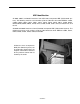
INTRODUCTION SECTION A. INTRODUCTION - MAINTENANCE SAFETY PRECAUTIONS A feed lines to system components can then be disconnected with minimal fluid loss. GENERAL This section contains the general safety precautions which must be observed during maintenance of the aerial platform. It is of utmost importance that maintenance personnel pay strict attention to these warnings and precautions to avoid possible injury to themselves or others, or damage to the equipment.
INTRODUCTION REVISON LOG Original Issue Revised Revised Revised Revised Revised Revised Revised Revised Revised A-2 September, 1996 April 1, 1999 August 4, 2000 November 15, 2000 February 6, 2001 August 29, 2001 June 13, 2002 March 21, 2003 January 28, 2004 September 26, 2005 – JLG Lift – 3120840
TABLE OF CONTENTS TABLE OF CONTENTS SUBJECT - SECTION, PARAGRAPH PAGE NO. SECTION A - INTRODUCTION - MAINTENANCE SAFETY PRECAUTIONS A B C General . . . . . . . . . . . . . . . . . . . . . . . . . . . . . . . . . . . . . . . . . . . . . . . . . . . . . . . . . . . . . . . . . . . . . .A-1 Hydraulic System Safety . . . . . . . . . . . . . . . . . . . . . . . . . . . . . . . . . . . . . . . . . . . . . . . . . . . . . . . . .A-1 Maintenance . . . . . . . . . . . . . . . . . . . . . . . . . . . . . . . . .
TABLE OF CONTENTS (Continued) TABLE OF CONTENTS (continued) SUBJECT - SECTION, PARAGRAPH PAGE NO. SECTION 2 - GENERAL 2.1 2.2 2.3 2.4 2.5 2.6 2.7 2.8 2.9 ii Machine Preparation, Inspection, and Maintenance . . . . . . . . . . . . . . . . . . . . . . . . . . . . . . . . . . .2-1 General . . . . . . . . . . . . . . . . . . . . . . . . . . . . . . . . . . . . . . . . . . . . . . . . . . . . . . . . . . . . . . . . . 2-1 Preparation, Inspection, and Maintenance . . . . . . . . . . . . . . . . . . . .
TABLE OF CONTENTS TABLE OF CONTENTS (continued) SUBJECT - SECTION, PARAGRAPH PAGE NO. SECTION 3 - CHASSIS & TURNTABLE 3.1 3.2 3.3 3.4 3.5 3.6 3.7 3.8 3.9 3.10 3.11 3120840 Drive Torque hub, Prior to S/N 75606 . . . . . . . . . . . . . . . . . . . . . . . . . . . . . . . . . . . . . . . . . . . . . .3-1 Disassembly. . . . . . . . . . . . . . . . . . . . . . . . . . . . . . . . . . . . . . . . . . . . . . . . . . . . . . . . . . . . . . 3-1 Cleaning and Inspection . . . . . . . . . . . . . . . . .
TABLE OF CONTENTS (Continued) TABLE OF CONTENTS (continued) SUBJECT - SECTION, PARAGRAPH 3.12 3.13 3.14 3.15 3.16 PAGE NO. Swing Brake - Mico . . . . . . . . . . . . . . . . . . . . . . . . . . . . . . . . . . . . . . . . . . . . . . . . . . . . . . . . . . . . .3-47 Disassembly. . . . . . . . . . . . . . . . . . . . . . . . . . . . . . . . . . . . . . . . . . . . . . . . . . . . . . . . . . . . . . 3-47 Inspection . . . . . . . . . . . . . . . . . . . . . . . . . . . . . . . . . . . . . . . . . . . .
TABLE OF CONTENTS TABLE OF CONTENTS (continued) SUBJECT - SECTION, PARAGRAPH 4.8 4.9 4.10 4.11 4.12 4.13 PAGE NO. Limit Switches and Cam Valve Adjustment . . . . . . . . . . . . . . . . . . . . . . . . . . . . . . . . . . . . . . . . . .4-22 Platform . . . . . . . . . . . . . . . . . . . . . . . . . . . . . . . . . . . . . . . . . . . . . . . . . . . . . . . . . . . . . . . . . . . . . .4-25 Platform Sections Replacement . . . . . . . . . . . . . . . . . . . . . . . . . . . . . . . . . . . . . . . . .
TABLE OF CONTENTS (Continued) TABLE OF CONTENTS (continued) SUBJECT - SECTION, PARAGRAPH 5.6 5.7 5.8 5.9 5.10 PAGE NO. Variable Displacement pump (M46 series). . . . . . . . . . . . . . . . . . . . . . . . . . . . . . . . . . . . . . . . . . . 5-32 Troubleshooting. . . . . . . . . . . . . . . . . . . . . . . . . . . . . . . . . . . . . . . . . . . . . . . . . . . . . . . . . . . 5-32 Inspections and Adjustments . . . . . . . . . . . . . . . . . . . . . . . . . . . . . . . . . . . . . . . . . . . . . .
TABLE OF CONTENTS LIST OF FIGURES FIGURE NO. 1-1. 1-2. 1-3. 1-4. 1-5. 2-1. 2-2. 2-3. 2-4. 2-5. 2-6. 2-7. 2-8. 2-9. 2-10. 2-11. 2-12. 2-13. 2-14. 3-1. 3-2. 3-3. 3-4. 3-5. 3-6. 3-7. 3-8. 3-9. 3-10. 3-11. 3-12. 3-13. 3-14. 3-15. 3-16. 3-17. 3-18. 3-19. 3-20. 3-21. 3-22. 3-23. 3-24. 3-25. 3-26. 3-27. 3-28. 3-29. 3-30. 3-31. 3-32. 3-33. 3-34. 3-35. 3120840 TITLE PAGE NO. 600S Lug Torques . . . . . . . . . . . . . . . . . . . . . . . . . . . . . . . . . . . . . . . . . . . . . . . . . . . . . . . . . . . . .
TABLE OF CONTENTS (Continued) LIST OF FIGURES (continued) FIGURE NO. 4-1. 4-2. 4-3. 4-4. 4-5. 4-6. 4-7. 4-8. 4-9. 4-10. 4-11. 4-12. 4-13. 4-14. 4-15. 4-16. 4-17. 4-18. 4-19. 4-20. 4-21. 4-22. 4-23. 4-24. 4-25. 4-26. 4-27. 4-29. 4-30. 4-31. 4-28. 4-32. 4-33. 4-34. 4-35. 4-36. 5-1. 5-2. 5-3. 5-4. 5-5. 5-6. 5-7. 5-8. 5-9. 5-10. 5-11. 5-12. 5-13. 5-14. 5-15. 5-16. 5-17. 5-18. viii TITLE PAGE NO. Dimensions of Boom Sections . . . . . . . . . . . . . . . . . . . . . . . . . . . . . . . . . . . . . . . . . .
TABLE OF CONTENTS LIST OF FIGURES (continued) FIGURE NO. 5-19. 5-20. 5-21. 5-22. 5-23. 5-24. 5-25. 5-26. 5-27. 5-28. 5-29. 5-30. 5-31. 5-32. 5-33. 5-34. 5-35. 5-36. 5-37. 5-38. 5-39. 5-40. 5-41. 5-42. 5-43. 6-1. 6-2. 6-3. 6-4. 6-5. 6-6. 6-7. 6-8. 7-1. 7-2. 7-3. 7-4. 7-5. 7-6. 7-7. 7-8. 7-9. 7-10. 7-11. 7-12. 7-13. 7-14. 7-15. 7-16. 7-17. 7-18. 7-19. 7-20. 7-21. 3120840 TITLE PAGE NO. Boom Positioning and Support, Cylinder Repair (A Models). . . . . . . . . . . . . . . . . . . . . . . . . . . . .
TABLE OF CONTENTS (Continued) LIST OF FIGURES (continued) FIGURE NO. 7-22. 7-23. 7-24. 7-25. 7-26. 7-27. 7-28. 7-29. 7-30. 7-31. 7-32. 7-33. 7-34. 7-35. 7-36. 7-37. 7-38. 7-39. 7-40. 7-41. 7-42. x TITLE PAGE NO. Electrical Schematic - Isuzu Engine - Sheet 2 of 4 . . . . . . . . . . . . . . . . . . . . . . . . . . . . . . . . . . . . .7-23 Electrical Schematic - Isuzu Engine - Sheet 3 of 4 . . . . . . . . . . . . . . . . . . . . . . . . . . . . . . . . . . . . .
TABLE OF CONTENTS LIST OF TABLES TABLE NO. 1-1 1-2 1-3 1-4 1-5 1-6 1-7 1-8 1-9 1-10 1-11 1-12 1-13 2-1 2-2 2-3 4-1 4-2 4-3 5-1 5-2 5-3 6-1 6-2 6-3 6-4 6-5 6-6 6-7 3120840 TITLE PAGE NO. Function Speeds (In Seconds) . . . . . . . . . . . . . . . . . . . . . . . . . . . . . . . . . . . . . . . . . . . . . . . . . . . .1-4 Torque Requirements . . . . . . . . . . . . . . . . . . . . . . . . . . . . . . . . . . . . . . . . . . . . . . . . . . . . . . . . . . .1-4 Hydraulic Oil . . . . . . . . . . . . . . .
TABLE OF CONTENTS (Continued) This page left blank intentionally.
SECTION 1 - SPECIFICATIONS SECTION 1. SPECIFICATIONS 1.1 Engine - Diesel (Water-Cooled) CAPACITIES Manufacturer/Model - Continental - TMD27. Fuel Tank Oil Capacity. 148 Liters (S Models) 6.7 Liters w/Filter. 114 Liters (A Models) 5.7 Liters w/o Filter. Hydraulic Oil Tank Low RPM - 1800. Gasoline/Diesel Power - 117 Liters with 10% air space (S Models) - 116 Liters) with 10% air space (A Models). High RPM - 2800.
SECTION 1 - SPECIFICATIONS Steer System (S Models) 1.3 Tires - 15 x 19.5, G 14 ply rating, directional tread, pneumatic, tire pressure -5 Bar. Travel Speed 600S. 2WD - 7.25 Km/hr. Tires - 15 x 19.5, G 14 ply rating, directional tread, foam filled. Toe-in, adjust for 6.35 mm overall. PERFORMANCE DATA 4WD - 6.44 Km/hr. Travel Speed 600A. 2WD - 5.8 Km/hr. Steer System (A Models) Tires - 14 x 17.5 NHS, G 14 ply rating, directional tread, pneumatic. 4WD - 6.4 Km/hr. Gradeability. Tires - 14 x 17.
SECTION 1 - SPECIFICATIONS Boom Elevation (S Models) Machine Width (S Models) 600S - +18.36 m 600S/600SJ/660SJ Models -1.87 m. 2WS/2WD - 2.42 m. 600SJ - +18.43 m 2WS/4WD - 2.42 m. -2.98 m. 4WS/2WD - 2.42 m. 660SJ - +20.31 m 4WS/4WD - 2.42 m. 3.49 m. Boom Elevation (A Models) 600A - +18.42 m -0.28 m. 600AJ - +18.46 m -0.83 m. Machine Weight approximately (600S) - 2WD - 9,979.2 kg. (600SJ) - 2WD - 10,660 kg. Machine Width (A Models) 600A/600AJ Models 2WS/2WD - 2.44 m. 2WS/4WD - 2.44 m.
SECTION 1 - SPECIFICATIONS Platform Rotate: Platform level and completely rotated one direction. Rotate the opposite direction, Record Time. Rotate the other direction, Record Time. 1.5 Table 1-2. Torque Requirements Articulating Jib: Platform level and centered with the boom. Start with the Jib down. Jib Up, Record Time. Jib Down, Record Time. Test Notes 1. Stop watch should be started with the function, not with the controller or switch. 2. All speed tests are run from the platform.
SECTION 1 - SPECIFICATIONS 1.6 LUBRICATION Deutz F4M1011F Engine Single Viscosity Oil (CD-SE, CD-SF). When Outside Temperature is Consistently Use SAE Viscosity Number Below +32°F. (+0°C.) 10W-30 Hydraulic Oil When Outside Temperature is Consistently Use SAE Viscosity Number -20°F. to +25°F. (-29°C. to +4°C.) *10W +5°F. to +50°F. (+15°C. to +10°C.) 20W-20 +40°F. to +85°F. (+4°C. to +30°C.) 30 HYDRAULIC SYSTEM OPERATING TEMPERATURE RANGE Above 75°F. (24°C.
SECTION 1 - SPECIFICATIONS Lubrication Specifications 1.7 PRESSURE SETTINGS Rexroth Valve (S Models) Table 1-5. Lubrication Specifications Main Relief - 207 Bar. KEY MPG SPECIFICATIONS Multipurpose Grease having a minimum dripping point of 350° F. Excellent water resistance and adhesive qualities, and being of extreme pressure type. (Timken OK 40 pounds minimum.) Upper Boom Lift Down - 103 Bar. Swing - 117 Bar. Steer - 124 Bar. Steer Reliefs - 4WS Front & Rear - 172 Bar.
SECTION 1 - SPECIFICATIONS 1.8 CYLINDER SPECIFICATIONS Table 1-6. Cylinder Specifications (S Models) DESRIPTON BORE STROKE ROD DIA. 600SJ 660SJ 600S 600SJ 660SJ 600S 600SJ 660SJ 600S Lift 6.00 (152.4) 6.00 (152.4) 6.00 (152.4) 44.6875 (1135.1) 44.6875 (1135.1) 44.6875 (1135.1) 3 (76.2) 3 (76.2) 3 (76.2) Telescope 3.5 (88.9) 3.5 (88.9) 3.5 (88.9) 143.1875 (3637) 168.4375 (4278.3) 177.75 (4514.9) 2.5 (63.5) 2.5 (63.5) 2.5 (63.5) Steer 2.5 (63.5) 2.5 (63.5) 2.5 (63.
SECTION 1 - SPECIFICATIONS 1.9 MAJOR COMPONENT WEIGHTS Table 1-8. Major Component Weights (S Models) 600SJ 660SJ 600S LB. KG. LB. KG. LB. KG. Platform Control Console 250 113 250 113 250 113 Platform Level Cylinder 60 27 60 27 46 21 Main Boom (Includes Lift Cyl.
SECTION 1 - SPECIFICATIONS BATTERIES, FILLED TIRES, COUNTERWEIGHT, ENGINE & PLATFORM) DO NOT MODIFY UNIT IN ANY WAY TO AFFECT STABILITY. 1.10 CRITICAL STABILITY WEIGHTS DO NOT REPLACE ITEMS CRITICAL TO STABILITY WITH ITEMS OF DIFFERENT WEIGHT OR SPECIFICATION (FOR EXAMPLE: Table 1-10. Critical Stability Weights (S Models) 600SJ 660SJ 600S LB. KG. LB. KG. LB. KG. Tire and Wheel (Ballasted Only) Size (15 - 19.
SECTION 1 - SPECIFICATIONS Figure 1-2.
SECTION 1 - SPECIFICATIONS Table 1-12.
SECTION 1 - SPECIFICATIONS Figure 1-3.
SECTION 1 - SPECIFICATIONS Table 1-13. Lubrication Chart - A Models Components Interval Number/Type Lube Points Capacity Hours Lube Comments 3 Months 150 hrs 6 Months 300 hrs 1 Year 600 hrs 2 Years 1200 hrs Lubrication 1 Swing Bearing 2 Grease Fittings A/R MPG X Remote Access 2 Wheel Bearings Repack A/R MPG X 3 Swing Drive Hub Level/Fill Plug 0.5 liters (1/2 Ful)l EPGL X Check level every 150 hrs/change 1200 hours 4 Wheel Drive Hub Level/Fill Plug 0.
SECTION 1 - SPECIFICATIONS the machine serial number is stamped on the left side of the frame. 1.11 SERIAL NUMBER LOCATIONS A serial number plate is affixed to the left rear side of the frame. If the serial number plate is damaged or missing, Figure 1-4.
UNPLATED CAP SCREWS 3120840 – JLG Lift – 40 48 32 40 32 36 24 32 20 28 18 24 16 24 14 20 13 20 12 18 11 18 10 16 9 14 8 12 7 12 7 12 6 12 6 12 Note: 1-1/2 1-1/2 1-1/4 1-1/8 1 7/8 3/4 5/8 9/16 1/2 7/16 3/8 5/16 1/4 10 8 6 4 0.0153 0.0168 0.0232 0.0258 0.0356 0.0374 0.0445 0.0508 0.0808 0.0925 0.1331 0.1473 0.1969 0.2230 0.2700 0.3015 0.3604 0.4061 0.4623 0.5156 0.5740 0.6502 0.8484 0.9474 1.1735 1.2929 1.5392 1.6840 1.9380 2.1742 2.4613 2.7254 2.9337 3.3401 3.5687 4.
SECTION 1 - SPECIFICATIONS This page left blank intentionally.
SECTION 2 - GENERAL SECTION 2. GENERAL 2.1 MACHINE PREPARATION, INSPECTION, AND MAINTENANCE General This section provides the necessary information needed by those personnel that are responsible to place the machine in operation readiness and maintain its safe operating condition. For maximum service life and safe operation, ensure that all the necessary inspections and maintenance have been completed before placing the machine into service.
SECTION 2 - GENERAL Table 2-1. Inspection and Maintenance Primary Responsibility Service Qualification Reference Prior to use each day; or At each Operator change. User or Operator User or Operator Operator and Safety Manual Pre-Delivery Inspection Prior to each sale, lease, or rental delivery. Owner, Dealer, or User Qualified JLG Mechanic Service and Maintenance Manual and applicable JLG inspection form.
SECTION 2 - GENERAL Component Disassembly and Reassembly When disassembling or reassembling a component, complete the procedural steps in sequence. Do not partially disassemble or assemble one part, then start on another. Always recheck your work to assure that nothing has been overlooked. Do not make any adjustments, other than those recommended, without obtaining proper approval.
SECTION 2 - GENERAL 2.3 3. The only exception to the above is to drain and fill the system with Mobil DTE 13 oil or its equivalent. This will allow start up at temperatures down to -20 degrees F (-29 degrees C). However, use of this oil will give poor performance at temperatures above 120 degrees F (49 degrees C). Systems using DTE 13 oil should not be operated at temperatures above 200 degrees F (94 degrees C) under any condition. LUBRICATION AND INFORMATION Hydraulic System 1.
SECTION 2 - GENERAL 2.4 CYLINDER DRIFT TEST 2.5 Maximum acceptable cylinder drift is to be measured using the following methods. PINS AND COMPOSITE BEARING REPAIR GUIDELINES Filament wound bearings. Platform Drift Measure the drift of the platform to the ground. Lower booms (if equipped) slightly elevated, upper boom fully extended with the rated load in the platform and power off. Maximum allowable drift is 2 inches (5 cm) in 10 minutes.
SECTION 2 - GENERAL 2.6 WELDING ON JLG EQUIPMENT 2.7 NOTE: This instruction applies to repairs, or modifications to the machine and to welding performed from the machine on an external structure, or component, Do the Following When Welding on JLG Equipment APPLYING SILICONE DIELECTRIC COMPOUND TO ELECTRICAL CONNECTIONS Silicone Dielectric Compound must be used on all electrical connections for the following reasons: • To prevent oxidation at the mechanical joint between male and female pins.
SECTION 2 - GENERAL 2.8 Assembly AMP CONNECTOR Check to be sure the wedge lock is in the open, or asshipped, position (See Figure 2-1.). Proceed as follows: Applying Silicone Dielectric Compound to AMP Connectors Silicone Dielectric Compound must be used on the AMP connections for the following reasons: • To prevent oxidation at the mechanical joint between male and female pins. • To prevent electrical malfunction caused by low level conductivity between pins when wet.
SECTION 2 - GENERAL Figure 2-3. Connector Assembly Figure 2 3. After all required contacts have been inserted, the wedge lock must be closed to its locked position. Release the locking latches by squeezing them inward (See Figure 2-4.). 4. Slide the wedge lock into the housing until it is flush with the housing (See Figure 2-5.). Figure 2-5. Connector Assembly Figure 4 Figure 2-4.
SECTION 2 - GENERAL Figure 2-6. Connector Disassembly Disassembly Service - Voltage Reading 1. Insert a 4.8 mm (3/16") wide screwdriver blade between the mating seal and one of the red wedge lock tabs. 2. Pry open the wedge lock to the open position. 3. While rotating the wire back and forth over a half turn (1/4 turn in each direction), gently pull the wire until the contact is removed. NOTE: The wedge lock should never be removed from the housing for insertion or removal of the contacts.
SECTION 2 - GENERAL Figure 2-7.
SECTION 2 - GENERAL 2.9 DT/DTP Series Disassembly DEUTSCH CONNECTORS DT/DTP Series Assembly A A B B C C D Figure 2-8. DT/DTP Contact Installation Figure 2-9. DT/DTP Contact Removal 1. Grasp crimped contact about 25mm behind the contact barrel. 2. Hold connector with rear grommet facing you. 3. Push contact straight into connector grommet until a click is felt. A slight tug will confirm that it is properly locked in place. 4.
SECTION 2 - GENERAL HD30/HDP20 Series Assembly HD30/HDP20 Series Disassembly B A A C C Figure 2-10. HD/HDP Contact Installation Figure 2-12. HD/HDP Contact Removal 1. Grasp contact about 25mm behind the contact crimp barrel. 1. With rear insert toward you, snap appropriate size extractor tool over the wire of contact to be removed. 2. Hold connector with rear grommet facing you. 3. Push contact straight into connector grommet until a positive stop is felt.
SECTION 2 - GENERAL Table 2-3.
SECTION 2 - GENERAL Table 2-3.
SECTION 2 - GENERAL Table 2-3.
SECTION 2 - GENERAL 4150548 A Figure 2-14.
SECTION 3 - CHASSIS & TURNTABLE SECTION 3. CHASSIS & TURNTABLE 3.1 Cleaning and Inspection DRIVE TORQUE HUB, PRIOR TO S/N 75606 1. Thoroughly clean all parts in an approved cleaning solvent. Disassembly 1. Position hub over suitable container and remove drain plugs (10) from unit. Allow oil to completely drain, then replace drain plugs. 2. Inspect bearing cups and cones for damage, pitting, corrosion, or excessive wear.
SECTION 3 - CHASSIS & TURNTABLE Figure 3-1.
SECTION 3 - CHASSIS & TURNTABLE Repair h. Apply a coat of grease or petroleum jelly to cluster gear bore. 1. Cover Assembly. a. Remove two bolts (25) securing disconnect cap (26) to cover (23) and remove cap. b. Remove two bolts (25) securing cover cap (24) to cover and remove cap. c. Remove disconnect rod (27) from cap and remove o-rings (28, 29) from cover cap. Discard o-rings. d. If necessary, remove pipe plug (30) from cover. e.
SECTION 3 - CHASSIS & TURNTABLE k. Place second set of sixteen needle rollers into cluster gear. Ensure chamfered side of hole in planet shaft is lined up with pin hole in carrier. l. Apply grease or petroleum jelly to tang side of two thrust washers. Place thrust washers against bosses in carrier with washer tang fitting into slot in carrier outside diameter. o. Drive anti-roll pin flush into carrier hole, locking planet shaft into place. p.
SECTION 3 - CHASSIS & TURNTABLE d. Place washer (31), spring (32), and washer (31), in that order, onto input shaft. 2. Place bearing cone (4) into bearing cup (3) in small end of hub. e. Install retaining ring into input shaft groove to secure spacers and spring to shaft. 3. Press new seal (2) into hub counter bore with flat metal side facing in. Use a flat object to ensure that seal is pressed evenly and is flush with hub face. Assembly 4. Lower hub onto spindle (1) with large open end up. 1.
SECTION 3 - CHASSIS & TURNTABLE 8. Place internal gear (12) onto end of spindle. 5. Place bearing cone (6) over end of spindle and into bearing cup. 9. Install thrust washers and thrust bearing (39, 40) on the portion of the spindle which extends into the internal gear. 6. Place bearing shim (8) over end of spindle and against bearing cone. 10. Install retaining ring (34) into input shaft retaining ring groove. EYE PROTECTION SHOULD BE WORN DURING RETAINING RING INSTALLATION. 7.
SECTION 3 - CHASSIS & TURNTABLE 11. Place input shaft assembly (35) into spindle bore with unsplined end facing out. ing of o-ring may be necessary to insure proper seating. 12. Place thrust spacer (36) over input shaft (35) with counter bore side facing spindle. 15. Place carrier assembly on a flat surface with large gears up and positioned as shown. Find punch marked tooth on each large gear and locate at 12 o’clock (straight up) from each planet pin.
SECTION 3 - CHASSIS & TURNTABLE mesh with internal gear. On ring gear, locate hole marked ‘X’ over one of counter bored holes in hub. 20. Install thrust washers and thrust bearing (39, 40) into carrier counter bore. NOTE: If gears do not mesh easily or carrier assembly does not rotate freely, then remove carrier and ring gear and check cluster gear timing. 21. Place o-ring (22) into cover assembly counter bore. Use petroleum jelly or grease to hold o-ring in place. 18.
SECTION 3 - CHASSIS & TURNTABLE 23. Locate four shoulder bolts (42), 90 degrees apart into counter bored holes in hub marked in step (13). Torque shoulder bolts to 64 Nm. 3.2 TORQUE HUB, DRIVE (AUBURN GEAR) Disassembly 1. Position hub over suitable container and remove drain plugs (27) from unit. Allow oil to completely drain, then replace drain plugs. 2. Remove twelve bolts (25) and flat washers (26) and the cover from the hub (9).
SECTION 3 - CHASSIS & TURNTABLE Figure 3-2.
SECTION 3 - CHASSIS & TURNTABLE 2. Assemble bearing cone (6) into cup (7) at seal end of hub (9) and press a new seal (5) into hub. Install boot seal (4) on the hub (9) if hub is so equipped. 3. Position spindle (3) upright on bench. Lubricate lips of seals (4) and (5) and lower hub onto spindle (3). Hub should be centered as it is lowered over spindle (3) to prevent seal damage. 4. Assemble bearing cone (11) over spindle (3) and into bearing cup (10).
SECTION 3 - CHASSIS & TURNTABLE 3.3 THE BRAKE TEST DRIVE TORQUE HUB, S/N 75606 TO PRESENT Reference: Sample Model 7HBE01F0B30057. The underlined letter is the brake option. Options are A, B, C, D, E, or X. Roll, Leak and Brake Testing Torque-Hub units should always be roll and leak tested before disassembly and after assembly to make sure that the unit's gears, bearings and seals are working properly. The following information briefly outlines what to look for when performing these tests.
SECTION 3 - CHASSIS & TURNTABLE 5. Using the same sequence, crisscross around the bolt circle and apply an equal torque to the remaining bolts. Main Disassembly 1. Perform Roll Check, Leak Check and Brake Check if applicable prior to disassembling the unit. 2. Drain oil from unit. Note the condition and volume of the oil. 3.
SECTION 3 - CHASSIS & TURNTABLE 1A. Spindle 1D. Housing 1E. Ring Gear 3. Input Carrier 4. Planet Gear 4E. Planet Shaft 4G. Roll Pin 4H. Thrust Washer 5. Retaining Ring 9. Input Shaft 10. First Stage Sun Gear 11. Second Stage Sun Gear 18. O-ring 19. Bolt 20. Retaining Ring Figure 3-4. Input Carrier 5. Remove the First Stage Sun Gear (10) if applicable.
SECTION 3 - CHASSIS & TURNTABLE 15. Slide the Planet Gear Subassembly (4) out of the Spindle (1A) being careful to not drop the Needle Bearings (4C) in the process. 16. Remove 4 Thrust Washers (4B), 28 Needle Rollers (4C) and the Thrust Spacer (4D) from the Second Stage Planet Gear (4F). 4B. Thrust Washer 4C. Needle Roller 17. Repeat Steps 12 though 16 for the remaining two Planet Gears (4F). 18. Remove the Thrust Washer (4H) from the counterbore in the Spindle (1A). 4D. Thrust Spacer 4F.
SECTION 3 - CHASSIS & TURNTABLE Input Carrier Disassembly 3A. Carrier 3B. Thrust Washer 3E. Planet Shaft 3F. Planet Gear 4G. Roll Pin Figure 3-6. Input Carrier 1. Using a 1/8” diameter punch, drive the Roll Pin (4G) into the Planet Shaft (3E) until it bottoms against the Carrier (3A). 2. Using a soft face hammer, tap the Planet Shaft (3E) out of the Carrier (3A). 3. Using a 1/8” diameter punch, drive the Roll Pin (4G) out of the Planet Shaft (3E).
SECTION 3 - CHASSIS & TURNTABLE Hub-Spindle Disassembly 1A. Barrel 1B. Seal 1C. Bearing Cone 1D. Hub 1F. Bearing Nut 1G. Setscrew 1H. Stud 1Q. Boot Seal Figure 3-8. Hub Spindle 6. If necessary, press 9 Studs (1H) out of Hub (1D). Locate Hub (1D) on Seal (1B) end. 1. Place unit on bench with Spindle (1A) end down. 2. Remove 2 Set Screws (1G) and Bearing Nut (1F) using T-206569. NOTE: The holes in the Bearing Nut (1F) for the Set Screws (1G) were staked for retention of the Set Screws (1G).
SECTION 3 - CHASSIS & TURNTABLE Spindle-Brake Disassembly 1A. Spindle 7. Coupling Subassembly 8A. Piston 8B. Pressure Plate 8C. Retaining Ring 8D. O-Ring 8E. Backup Ring 8F. O-Ring 8H. Backup Ring 8J. Rotor 8K. Stator 8L. Compression Spring 12. Plastic Plug 21. Pipe Plug 22. Flat Head Capscrew Figure 3-9. Spindle Brake NOTE: This procedure applies only to units with integral Input Brake (8). EYE PROTECTION MUST BE WORN WHILE PERFORMING THE STEPS 1-3 IN THIS PROCEDURE. 1.
SECTION 3 - CHASSIS & TURNTABLE Pressure Plate (8B). Then, remove Flat Head Cap Screws (22) and Pressure Plate (8B) from brake cavity in Spindle (1A). 4. Remove Compression Springs (8L) from Piston (8A). EYE PROTECTION MUST BE WORN WHILE PERFORMING THE NEXT STEP IN THIS PROCEDURE. 5.
SECTION 3 - CHASSIS & TURNTABLE Cover Disassembly 2. Thrust Washer 6A. Cover 6B. Disengage Cap 6C. Bolt 6D. Disengage Rod 6E. O-Ring 6F. Pipe Plug 17. O-Ring Figure 3-11. Cover 1. Remove O-Ring (17) from groove in Cover (6A). 2. Remove Thrust Washer (2) from Cover (6A) pockets. 3. Unscrew two Hex Head Bolts (6C) and remove Disengage Cap (6B) from Cover (6A). 5. Use appropriate tool to remove O-ring (6E) from internal groove in Cover (6A). 6. Remove two O-Ring Pipe Plugs (6F) from Cover (6A). 4.
SECTION 3 - CHASSIS & TURNTABLE Input Carrier Sub-Assembly Output Planet Gear Sub-Assembly 1. Apply a liberal coat of grease to the bore of one Input Planet Gear (3F). 1. Apply a liberal coat of grease to the bore of one Output Planet Gear (4F). 2. Line the inside of the Planet Gear (3F) with 14 Needle Rollers (3C). 2. Line the inside of the Planet Gear (4F) with 14 Needle Rollers (4C). NOTE: The last roller installed must be installed end wise.
SECTION 3 - CHASSIS & TURNTABLE 9. Install small Backup Ring (8H) in the small-diameter groove near the top of the Piston (8A), on top of the small O-Ring (8F). 6. Set Spindle assembly (1A) on the bench with the flange down. Turn Hub (1D) over and lower onto Spindle (5). Install boot (21) if applicable. 10. Insert Piston (8A) into Spindle (1A) until it contacts the Stator (8K). 7. Install Bearing Cone of part (1C) into Bearing Cup, position "A". 8. Apply Loctite 243 on Bearing Nut (1F) thread.
SECTION 3 - CHASSIS & TURNTABLE Cover Sub-Assembly 1. Grease O-Ring (6E) and insert into internal groove in Cover (6A). 2. Assemble Disengage Cap (6B) onto Cover (6A) using two Hex Head Bolts (6C). Torque bolts to 7080 in-lbs. 11. Install Cover Sub-Assembly (6) into Ring Gear (1E) counterbore and install Retaining Ring (6G) into groove in Ring Gear (1E). 12. Attach ID Tag (15) onto unit using Drive Screws (16). 13. Check disconnect, roll and air check unit, leak check brake, and record release pressure.
SECTION 3 - CHASSIS & TURNTABLE 1A. Spindle 1B. Lip Seal 1C. Tapered Bearing 1D. Housing 1E. Ring Gear 1F. Bearing Nut 1G. Setscrew 1H. Stud 1K. Retaining Ring 1L. Spring 1M. Thrust Washer 1Q. Seal Boot 2. Thrust Spacer 3A. Carrier 3B. Thrust Washer 3C. Needle Bearing 3E. Planet Shaft 3F. Planet Gear 4B. Thrust Washer 4C. Needle Bearing 4D. Thrust Spacer 4E. Planet Shaft 4F. Planet Gear 4G. Roll Pin 4H. Thrust Washer 5. Retaining Ring 6A. Cover 6B. Disengage Cap 6C. Bolt 6D. Dowel Pin 6E. O-Ring 6F.
SECTION 3 - CHASSIS & TURNTABLE Figure 3-13. Bearing Cup Pressing Tool Figure 3-14.
SECTION 3 - CHASSIS & TURNTABLE Figure 3-15. Bearing Cup Pressing Tool Figure 3-16.
SECTION 3 - CHASSIS & TURNTABLE 3.4 Assembly DRIVE BRAKE - MICO NOTE: Lubricate all seals and o-rings with clean hydraulic oil prior to assembly. Disassembly 1. With shaft protrusion downward, remove end cover (13) by removing capscrews (12). 1. Press new rotary seal (1) into housing (7). Note the direction of seal. 2. Install new bearing (2) on shaft (4). END COVER IS UNDER SPRING TENSION OF APPROXIMATELY 681 KG. THE FOUR CAPSCREWS SHOULD BE LOOSENED EVENLY TO RELIEVE THIS FORCE.
SECTION 3 - CHASSIS & TURNTABLE Figure 3-17.
SECTION 3 - CHASSIS & TURNTABLE 3.5 Remove chocks from wheels as required. FREE WHEELING OPTION To Disengage Drive Motors and Brakes (Free Wheel) for Towing, etc. DISCONNECT CAP 1. Chock wheels securely if not on flat level surface. 2. Disconnect both drive hubs by inverting disconnect caps in center of hubs. If equipped, move steer/tow selector valve to float (tow) position by pulling valve knob out. To Engage Drive Motors and Brakes (Normal Operation) DRIVE HUB Drive Hub Engaged 1.
SECTION 3 - CHASSIS & TURNTABLE 3.6 Same sealing kit like shown above only seal material changed to Viton DRIVE MOTOR (600S, 600A 4WD) Spare Parts Kits Sealing kit, existing spare parts: shaft sealing ring, 6 different O-rings and a circlip (sealing mat.
SECTION 3 - CHASSIS & TURNTABLE Bearing set/miscellaneous parts Spare parts kit DFR pilot valve Replacing the Drive Shaft Seal Rotary group complete 9 pistons, cylinder sub-assembly, valve plate (cw or ccw corresponding to the order) retaining plate and retaining ball. 1. Remove the snap ring Swash Plate 2. Change the shaft seal and check its sliding surface (drive shaft) and housing, grease the sealing ring. Parts of the control device: control piston, piston rod, plug, spring stopper max flow, hex.
SECTION 3 - CHASSIS & TURNTABLE 4. Assemble the sealing ring. The fitting tool will hold the sealing ring in the correct position in the pump housing. Disassembly and Assembly 5. Assemble the snap ring. 1. Disassemble the pilot valve. 2. Mark the position of the port plate and remove the socket screw from the port plate. 6. Assemble the snap ring in the correct position. 3. Remove the port plate together with the valve plate (hold the valve plate so that the plate can’t fall down).
SECTION 3 - CHASSIS & TURNTABLE 4. Remove the O-ring. 8. Loosen the retaining nut of the stopper max flow and remove it. 5. Disassemble the taper roller bearing. 9. Turn in the stopper max flow to get swivel angle zero. 6. Remove the adjustment shim. 10. Disassemble the rotary group in horizontal position. 7. Unscrew the cap nut and remove it. 11. Disassemble the stopper - max. flow.
SECTION 3 - CHASSIS & TURNTABLE 12. Remove the threaded pin (stopper - max.flow) 16. Disassembly of the swash plate. 13. Disassemble the plug. 17. Remove the spring. 14. Disassemble the control piston while moving the swash plate. 18. Remove both bearing shells. 19. Remove the drive shaft. 15. The swash plate must be lifted a little bit to disassemble the piston rod.
SECTION 3 - CHASSIS & TURNTABLE 23. Remove the O-ring. Lifting of the valve plate isn’t shown. 20. Remove the snap ring. 21. Disassemble the sealing ring. 24. A usual commercial bearing puller is used to disassemble the external bearing ring of the taper roller bearing inside the port plate. Take care not to damage the surface of the port plate. 22. The external front bearing ring is pulled out of the pump housing. 25.
SECTION 3 - CHASSIS & TURNTABLE Assembly Notes 4. Pumps counterclockwise driven must have a position of the valve plate 4 degrees de-centered in ccw position. 1. Measurement of the taper roller bearing pretension. 2. Note that there is a correct connection of the piston rod and the swash plate. 5. Assembly of the port plate and the pump housing: Note the correct position of the drilling that connects high pressure to the control valve.
SECTION 3 - CHASSIS & TURNTABLE NOTE: Differential volume if you are rotating the threaded pin each rotation is appr. 3,1 cm3. Figure 3-19.
SECTION 3 - CHASSIS & TURNTABLE Figure 3-20. Drive Motor Adjustment (S Models) Testing and Setup DR: When pressure line is closed adjust the pressure of the controller (if it’s DFR design then open the adjustable orifice and increase force of the spring - FR -). Mechanical flow limiter: While screwing in the threaded pin you will be able to reduce the flow from Vg max to 50% of Vg max. 3.
SECTION 3 - CHASSIS & TURNTABLE 3.8 3. Using a Phillips screwdriver, remove screw from connection on the brake valve and remove connector as shown. OSCILLATING AXLE BLEEDING PROCEDURE AND LOCKOUT TEST Lockout Cylinder Bleeding ENSURE PLATFORM IS FULLY LOWERED AND BOOM IS CENTERED OVER REAR AXLE PRIOR TO BEGINNING BLEEDING PROCEDURE. ENS URE MACH I NE IS ON A LEVEL SURFACE AND REAR WHEELS ARE BLOCKED, BRAKE WIRE IS DISCONNECTED. 1.
SECTION 3 - CHASSIS & TURNTABLE Oscillating Axle Lockout Test 9. Place the 6 inch (15.2 cm) high block with ascension ramp in front of right front wheel. LOCKOUT SYSTEM TEST MUST BE PERFORMED QUARTERLY, ANY TIME A SYSTEM COMPONENT IS REPLACED, OR WHEN IMPROPER SYSTEM OPERATION IS SUSPECTED. NOTE: Ensure boom is fully retracted, lowered, and centered between drive wheels prior to beginning lockout cylinder test. 10.
SECTION 3 - CHASSIS & TURNTABLE 3.9 STEER ADJUSTMENTS (S MODELS) 3.10 SWING HUB NOTE: Spindles do not stop on cylinder stroke. Adjust steering stops as follows: Adjust item #1 to achieve 44° inside turn angles. Steer full left and adjust RH item #2 to contact axle. Steer full right and adjust LH item #2 to contact axle. (2WS/2WD) Adjustment Procedures NOTE: The swing bearing high spot is usually marked by colored paint. Spindles do not stop on cylinder stroke.
SECTION 3 - CHASSIS & TURNTABLE Figure 3-25. Swing Torque Hub Adjustment 2. Check the turntable to bearing. Attach bolts as follows: 3.11 SWING BEARING a. Elevate the fully retracted boom to 70 degrees (full elevation). Turntable Bearing Mounting Bolt Condition Check b. At the positions indicated on Figure 3-26., Swing Bearing Bolt Feeler Gauge Check, try and insert the .0015" feeler gauge between the bolt head and hardened washer at the arrow indicated position.
SECTION 3 - CHASSIS & TURNTABLE Wear Tolerance.(S & A Models) 5. If bearing inspection shows no defects, reassemble and return to service. 1. From the underside of the machine, at rear center, with the boom fully elevated and fully retracted, as shown in (Figure 3-29., Swing Bearing Tolerance Boom Placement (S Models) and Figure 3-28., Swing Bearing Tolerance Boom Placement (A Models), using a magnetic base dial indicator, measure and record the distance between the swing bearing and turntable.
Figure 3-28.
Figure 3-29.
SECTION 3 - CHASSIS & TURNTABLE Swing Bearing Replacement Ensure the scribed line of the outer race of the bearing aligns with the scribed line on the frame. If a new swing bearing is used, ensure that the filler plug fitting is at 90 degrees from the fore and aft center line of the frame. 1. Removal. a. From Ground Control station, operate the boom adequately to provide access to frame opening or, if equipped, to rotary coupling.
SECTION 3 - CHASSIS & TURNTABLE Figure 3-30. Swing Bearing Torque Sequence j. Install the rotary coupling retaining yoke brackets, apply a light coating of Loctite #242 to the attaching bolts and secure the yoke to the turntable with the mounting hardware. 3.12 SWING BRAKE - MICO Disassembly k. Connect the hydraulic lines to the rotary coupling as tagged prior to removal. 1. With shaft protrusion downward, remove end cover (13) by removing capscrews (12). l.
SECTION 3 - CHASSIS & TURNTABLE Figure 3-31.
SECTION 3 - CHASSIS & TURNTABLE 9. Remove shaft by pressing or using a soft mallet on male end of shaft (51). 10. Install new case seal (11) in housing (52), then install bleeder screw (14) in end cover. 10. Remove retaining ring (54) bearing (2) from shaft (51). 11. Position end cover (13) on housing (52), aligning dowel pins (15) with holes in end cover. 11. Press rotary seal (1) from housing (51). Insert capscrews (12) and tighten evenly to draw end cover (13) to housing (52).
SECTION 3 - CHASSIS & TURNTABLE Procedure 3.14 SPARK ARRESTER CLEANING INSTRUCTIONS 1. Remove the cleanout plug in the bottom of spark arrester (muffler). 2. Without causing deformation (or any type of damage to the spark arrester) repeatedly tap on the arrester near the cleanout plug. This may be enough to begin drainage of the spark trap. NOTE: Never run fuel tank dry. Diesel engines cannot be restarted after running out of fuel until fuel system has been air-vented or bled of air.
SECTION 3 - CHASSIS & TURNTABLE 1. Remove bolt which secures engine tray to the turntable. Swing engine tray out to gain access to RPM adjustments. 2. Disconnect wire harness from ADDCO, install JLG wire harness kit #4921850 to the ADDCO and engine harness as shown in diagram below. Start the engine and allow it to come up to operating temperature. Position toggle switch to MID engine.
SECTION 3 - CHASSIS & TURNTABLE Figure 3-35.
SECTION 4 - BOOM & PLATFORM SECTION 4. BOOM & PLATFORM 4.1 5. Repeat the torque procedure in step #4 to the extend wire ropes (turntable end). BOOM ROPE TORQUING PROCEDURES 6. Extend the boom 0.6 to 0.9 meters using the telescope function. Repeat step #4. Torque Procedures (S Models) 1. Position boom in fully down and fully retracted position. 7. Retract the boom 0.3 to 0.6 meters using the telescope function. Do not bottom out telescope cylinder. Repeat step #5. 8. Extend the boom approximately 0.
SECTION 4 - BOOM & PLATFORM 4.3 WIRE ROPE (S MODELS) Each day before using the machine: 1. Raise the main boom to approximately horizontal. 2. Extend and retract the boom sections. 3. Check for delayed movement of the fly section, which indicates loose wire ropes. Inspection NOTE: The pictures in this paragraph are just samples to show the replacement criteria of the rope. 1. Inspect ropes for broken wires, particularly valley wire breaks and breaks at end terminations.
SECTION 4 - BOOM & PLATFORM 6. Inspect sheaves with a groove wearout gauge for excessive wear. Replacement Criteria 1. Sheaves and wire rope must be replaced as sets. 2. Rusted or corroded wire ropes. 3. Kinked, “bird caged”, or crushed ropes. 4. Ropes at end of adjustment range. 5. Sheaves failing wearout gage inspection. 6. Ropes with 6 total broken wires in one rope lay, 3 in one strand in one rope lay, 1 valley break, or 1 break at any end termination.
SECTION 4 - BOOM & PLATFORM Figure 4-5.
SECTION 4 - BOOM & PLATFORM Figure 4-6.
SECTION 4 - BOOM & PLATFORM Figure 4-7. Boom Assembly Cutaway - S Models - Sheet 3 of 3 2. Remove the rotator and slave level cylinder from the fly boom as follows: retain any residual hydraulic fluid. Cap hydraulic lines and ports. Remove the slave cylinder. a. Tag and disconnect hydraulic lines to rotator. Use suitable container to retain any residual hydraulic fluid. Cap hydraulic lines and ports. b. Remove hardware from pin #1. Using a suitable brass drift and hammer remove pin #1 from the fly boom.
SECTION 4 - BOOM & PLATFORM 3. Remove the powertrack from the boom as follows: a. Disconnect wiring harness from ground control box. HYDRAULIC LINES AND PORTS SHOULD BE CAPPED IMMEDIATELY AFTER DISCONNECTING LINES TO AVOID ENTRY OF CONTAMINANTS INTO SYSTEM. HYDRAULIC LINES AND PORTS SHOULD BE CAPPED IMMEDIATELY AFTER DISCONNECTING LINES TO AVOID ENTRY OF CONTAMINANTS INTO SYSTEM. b. Tag and disconnect hydraulic lines from telescope cylinder.
SECTION 4 - BOOM & PLATFORM Disassembly of Boom Sections 1. Remove hardware securing the push bar to aft end of the telescope cylinder, then remove pin from cylinder. 2. Remove hardware securing the cover plate on the bottom front of the base boom section. WHEN REMOVING THE TELESCOPE CYLINDER FROM THE BOOM, IT MAY BE NECESSARY AT SOME POINT IN ORDER TO CLEAR ASSEMBLIES MOUNTED WITHIN THE BOOM. CARE MUST BE TAKEN TO MOVE THE CYLINDER SLOWLY FROM THE BOOM.
SECTION 4 - BOOM & PLATFORM 12. Remove hardware which secures the wear pads to the aft end of mid boom section; remove the wear pads from the top, sides and bottom of the mid boom section. Inspection NOTE: When inspecting pins and bearings Ref. to section 2 General. 13. Remove hardware which secures the sheave guards and sheave assemblies to mid boom section, remove sheave assemblies from mid boom section. 14.
SECTION 4 - BOOM & PLATFORM 4. Install retract wire ropes into aft end of fly section, route wire ropes thru holes in side of fly boom section and pull into slot. 8. Inspect inner diameter of boom pivot bushing for scoring, distortion, wear, or other damage. Replace bearing as necessary. (See section 2 General). 9. Inspect all wear pads for excessive wear or other damage. Replace pads when worn to within 3.2 mm of threaded insert. 10.
SECTION 4 - BOOM & PLATFORM with mounting hardware. Position retract wire ropes onto the sheaves. 10. Install sheave guards to aft end of mid boom section and secure with mounting hardware. 11. Slide mid boom section into the base boom section. Allow the retraction wire ropes to trail between the bottom surfaces of boom sections. Shim boom, if necessary, for a total of 1.6 mm clearance. 12. Install wear pads into the forward position of the base boom section.
SECTION 4 - BOOM & PLATFORM a. Align holes in powertrack rail with attachment holes in side of the base boom section. Secure the rail with mounting hardware. 4. Align push bar pivot hole with pivot holes in turntable. Install push bar pivot pin, ensuring that location of hole in pin is aligned with attach point on turntable. b. Install powertrack to rail with mounting hardware. 5. If necessary, gently tap pin into position with soft headed mallet. Secure pin mounting hardware. c.
SECTION 4 - BOOM & PLATFORM b. Tag and disconnect hydraulic lines from connectors at boom assembly. Use suitable container to retain any residual hydraulic fluid. Cap hydraulic lines and ports. c. Supporting the rotator, remove hardware from pin #2. Using a suitable brass drift and hammer remove pin #2 from the fly boom and remove rotator. c. Disconnect dual capacity indicator limit switch from side of boom section. d.
SECTION 4 - BOOM & PLATFORM Figure 4-19.
SECTION 4 - BOOM & PLATFORM f. Using a suitable brass drift and hammer, remove the master cylinder pin from base boom. 5. Inspect all wear pads for excessive wear, or other damage. Replace pads when worn to within 3.2 mm of threaded insert. g. Remove hardware securing the boom pivot pin to the turntable upright. 6. Inspect all threaded components for damage such as stretching, thread deformation, or twisting. Replace as necessary. h.
SECTION 4 - BOOM & PLATFORM Installation residual hydraulic fluid. Cap hydraulic lines and ports. 1. Using a suitable lifting device, position boom assembly on turntable so that the pivot holes in both boom and turntable are aligned. e. Remove mounting hardware from master cylinder barrel end. Using a suitable brass drift and hammer remove pin #2 from tower upright. 2. Install boom pivot pin, ensuring that location of hole in pin is aligned with attach point on turntable. f.
SECTION 4 - BOOM & PLATFORM c. Using suitable lifting device, support the tower boom assembly at it’s approximate center of gravity. 5. Remove mounting hardware which secures the powertrack to the top of the tower base section, then remove powertrack. d. Remove mounting hardware from lower lift cylinder rod end. Using a suitable brass drift and hammer, remove pin #1 from the tower boom assembly. 6. Remove mounting hardware from tower boom telescope cylinder barrel end. 7.
SECTION 4 - BOOM & PLATFORM Inspection 4. Align tower telescope cylinder with attach holes in tower fly boom. Using a soft head mallet, install the cylinder pin into tower fly boom and secure with mounting hardware. NOTE: Refer to section 2 General. 1. Inspect tower boom pivot pin for wear, scoring, tapering and ovality, or other damage. Replace pins as necessary. 5. Secure the sling and lifting device at the tower fly boom assembly’s approximate center of gravity. 6.
SECTION 4 - BOOM & PLATFORM 7. Using suitable lifting device, position upright on tower boom assembly so that the pivot holes in both upright and tower boom are aligned. Disassembly 1. Remove mounting hardware from articulating jib boom pivot pins #3 and #4. Using a suitable brass drift and hammer, remove the pins from articulating jib boom pivot weldment. 8.
SECTION 4 - BOOM & PLATFORM Assembly Main Boom Telescope Cylinder Removal NOTE: For location of components See Section 4-23., Location of Components - Articulating Jib Boom. 8. Place machine on a flat and level surface, with main boom in the horizontal position. 1. Align lift cylinder with attach holes in articulating jib boom. Using a soft head mallet, install cylinder pin #7 into articulating jib boom and secure with mounting hardware. 9. Shut down engine. Support main boom basket end with a prop.
SECTION 4 - BOOM & PLATFORM 16. Remove hardware securing telescope cylinder to aft end of the mid boom section. WHEN REMOVING THE TELESCOPE CYLINDER FROM THE BOOM, IT MAY BE NECESSARY AT SOME POINT TO TURN THE CYLINDER SLIGHTLY IN ORD ER TO CLEAR ASSEM BLIES MOUNTED WITHIN THE BOOM. CARE MUST BE TAKEN TO MOVE THE CYLINDER SLOWLY INTO POSITION: DAMAGE TO COMPONENTS MAY RESULT FROM FORCIBLE IMPACT WITH THESE ASSEMBLIES. 17. Remove bolts securing cable attach bar to top of fly boom section. 5.
SECTION 4 - BOOM & PLATFORM Main Boom Lift Cylinder Removal 4. Using auxiliary power, extend the cylinder rod until the attach pin hole aligns with those in the boom. Using a suitable soft mallet, drive the cylinder rod attach pin through the boom and lift cylinder. Secure the pin in place with attaching hardware. 1. Place the machine on a flat and level surface. Start the engine and place the main boom in the horizontal position. Shut down engine and prop the boom. See Section 4-24.
SECTION 4 - BOOM & PLATFORM Figure 4-25.
SECTION 4 - BOOM & PLATFORM Figure 4-26.
SECTION 4 - BOOM & PLATFORM 4.9 3. Using a suitable hammer and chisel remove the portion of end cap securing setscrew. PLATFORM Platform Sections Replacement The platform is made up of five sections: floor, right side, left side, back (console box mounting.) and gate. The sections are secured with huck magna grip fastener and collars. Replace damaged platform sections as follows: 1. Support the huck collar with a sledge hammer or other suitable support. 2.
SECTION 4 - BOOM & PLATFORM Figure 4-28.
SECTION 4 - BOOM & PLATFORM 6. Place two (2) 3/8"x16NC bolts in threaded holes in bottom of the actuator. Using a suitable bar, unscrew the end cap (5). Remove the end cap from actuator (1). 8. Remove piston sleeve (3) from housing (1). Figure 4-34. Removing Sleeve from Housing 9. Remove all seals and bearings from grooves. Discard seals. Figure 4-32. Removing End Cap 7. Remove the shaft (2) from piston sleeve (3) and the actuator housing (1). Inspection 1. Clean all parts thoroughly. 2.
SECTION 4 - BOOM & PLATFORM 3. Install new seals (11), back-up ring (12), cap bearing (13), bearing packing (14) and thrust ring (10) on end cap (5). 4. Place the actuator in the vertical position, install the piston sleeve (3) in timed relation to the housing (1). DO NOT MISALIGN THE SLEEVE TOO MUCH ANY ONE WAY, AS IT WILL MARK THE CYLINDER BORE. NOTE: The timing marks (the small punch marks on the face of each gear), must be aligned for proper shaft orientation. (See Actuator Timing.) 5.
SECTION 4 - BOOM & PLATFORM Lift, Swing, and Drive Cards 1. Center the input potentiometers. Power up the card, but do not start the engine. Place the common lead of a voltmeter on pin #6 and place the other lead on pin #8. Rotate the potentiometer, leaving the joystick in the center position, until the voltmeter reads 2.5 volts. Secure the set screw on the potentiometer. When the potentiometer is centered and the joystick is in the center position, LED #3 should not be illuminated. 2.
SECTION 4 - BOOM & PLATFORM 4.12 FOOT SWITCH ADJUSTMENT Table 4-2. Flow Control Card Settings S Models Function Adjust so that functions will operate when pedal is at center of travel. If switch operates within last 6.35 mm of travel, top or bottom, it should be adjusted. Minimum Current Maximum Current Lift Up 450 to 55o mA 1400 to 1500 mA Lift Down 450 to 550 mA 1400 to 1500 mA 4.
SECTION 5 - HYDRAULICS SECTION 5. HYDRAULICS 5.1 retract cylinder. If leakage continues at a rate of 6-8 drops per minute or more, cylinder repair must be made. CYLINDERS - THEORY OF OPERATION Systems Incorporating Double Acting Cylinders Cylinders are of the double acting type.
SECTION 5 - HYDRAULICS ports. If leakage occurs at a rate of 6-8 drops per minute or more, the piston seals are defective and must be replaced. 4. To check piston seals, carefully remove the counterbalance valve from the retract port. After initial discharge, there should be no further leakage from the ports. If leakage occurs at a rate of 6-8 drops per minute or more, the piston seals are defective and must be replaced. 5.
SECTION 5 - HYDRAULICS 4. Place the cylinder barrel into a suitable holding fixture. free from the groove, the remainder can be easily pried free using ones fingers or pliers. 8. Attach a suitable pulling device to the cylinder rod port block end or cylinder rod end, as applicable. Figure 5-1. Cylinder Barrel Support 5. Mark cylinder head and barrel with a center punch for easy realignment.
SECTION 5 - HYDRAULICS tighten the cap screw(s) until the bushing is loose on the piston. 8. Inspect seal and o-ring grooves in piston for burrs and sharp edges. Dress applicable surfaces as necessary. 14. Remove the bushing from the piston. 9. Inspect cylinder head inside diameter for scoring or other damage and for ovality and tapering. Replace as necessary. 10. Inspect threaded portion of head for damage. Dress threads as necessary. 11.
SECTION 5 - HYDRAULICS Assembly NOTE: Prior to cylinder assembly, ensure that the proper cylinder seal kit is used. See your JLG Parts Manual. Apply a light film of hydraulic oil to all components prior to assembly. 1. A special tool is used to install a new rod seal into the applicable cylinder head gland groove. Figure 5-7. Poly-Pak Piston Seal Installation Figure 5-6. Rod Seal Installation Figure 5-8. Wiper Seal Installation WHEN INSTALLING ‘POLY-PAK’ PISTON SEALS, ENSURE SEALS ARE INSTALLED PROPERLY.
SECTION 5 - HYDRAULICS 5. Carefully slide the piston spacer on the rod. 9. Carefully thread the piston on the cylinder rod hand tight, ensuring that the o-ring and back-up rings are not damaged or dislodged. NOTE: Upper telescope cylinder piston has an o-ring installed inside the spacer. 6. If applicable, correctly place new o-ring in the inner piston diameter groove. (The backup ring side facing the O-ring is grooved.) 7.
SECTION 5 - HYDRAULICS 13. After the screws have been torqued, tap the tapered bushing with a hammer (16 to 24 oz.) and brass shaft (approximately 3/4" in diameter) as follows; a. Place the shaft against the cylinder rod and in contact with the bushing in the spaces between the capscrews. b. Tap each space once; this means the tapered bushing is tapped 3 times as there are 3 spaces between the capscrews. EXTREME CARE SHOULD BE TAKEN WHEN INSTALLING THE CYLINDER ROD, HEAD, AND PISTON.
SECTION 5 - HYDRAULICS Table 5-1. Cylinder Head and Tapered Bushing Torque Specifications. (S Models) Description Head Torque Value (Wet) Table 5-3. Cylinder Head and Tapered Bushing Torque Specifications. (A Models) Tapered Bushing Torque Value (Wet) Description Head Torque Value (Wet) Tapered Bushing Torque Value (Wet) Lift Cylinder 275 ft. lbs. (373 Nm) 30 ft. lbs. (41 Nm) Upper Lift Cylinder 80 ft. lbs. (109 Nm) 9 ft. lbs. (12 Nm) Articulating Lift Cylinder 30 ft. lbs. (41 Nm) 5 ft.
SECTION 5 - HYDRAULICS 5.4 8. Remove hardware securing cable adjustment block to aft end of the base boom section and remove block. CYLINDER REMOVAL AND INSTALLATION (S MODELS) 9. Remove hardware securing telescope cylinder to aft end of the mid boom section. Main Boom Telescope Cylinder Removal 1. Place machine on a flat and level surface, with main boom in the horizontal position. 2. Shut down engine. Support main boom basket end with a prop. See Figure 5-14.
SECTION 5 - HYDRAULICS 3. Secure the sling and lifting device at the telescope cylinder’s approximate center of gravity, and lift the cylinder to the aft end of the boom assembly. 4. Install extend cable mounting blocks to threaded ends of cables. Loosely install nuts and jam nuts onto the threaded ends of cables. 11. Align holes in push bar with holes in turntable. Install push bar pin and secure with mounting hardware. NOTE: Boom cables must be torqued after installation of the telescope cylinder.
SECTION 5 - HYDRAULICS Figure 5-15. Location of Components - Telescope and Lift Cylinder Main Boom Lift Cylinder Installation 5.5 1. Install lift cylinder in place using suitable slings or supports, aligning attach pin mounting holes on the turntable. CYLINDER REMOVAL AND INSTALLATION (A MODELS) Main Boom Telescope Cylinder Removal 2. Using a suitable drift, drive the barrel end attach pin through the mounting holes in the lift cylinder and the turntable.
SECTION 5 - HYDRAULICS 4. Remove the retaining rings that retain the telescope cylinder rod to the fly boom. 6. Carefully install the telescope cylinder barrel end support into slots in base boom and secure with blocks and bolts. Use Loctite #242 on bolts. Shim as necessary. 5. Using a suitable brass drift, carefully drive telescope cylinder rod pin #1 from the fly boom. 7. Remove applicable hydraulic line and port caps and correctly connect the hydraulic lines to the telescope cylinder.
SECTION 5 - HYDRAULICS Main Boom Lift Cylinder Installation Upright Level Cylinder Removal 1. Install lift cylinder in place using suitable slings or supports, aligning attach pin mounting holes on the upright. 2. Using a suitable drift, drive barrel end attach pin #3 through the mounting holes in the lift cylinder and the upright. Secure in place with the pin retaining hardware. 1.
SECTION 5 - HYDRAULICS 4. With overhead crane supporting upper boom assembly. Raise boom until tension is released from cylinder pin #1. 7. Remove overhead crane from upper boom. Activate hydraulic system. 8. Using all applicable safety precautions, operate the boom functions. Check for correct operation and hydraulic leaks. Secure as necessary. 5. Using a suitable drift, drive the barrel end attach pin #1 through the mounting holes in the upright and leveling cylinder. 6.
SECTION 5 - HYDRAULICS Figure 5-18. Tower Telescope Cylinder Removal 4. Using an appropriate brass drift, drive the rod attach pin through the aligned bushings. Secure pin with attaching hardware. Tower Telescope Cylinder Removal 5. Remove caps from cylinder hydraulic lines and correctly install lines to cylinder as previously tagged during Removal. 6. Remove boom prop and overhead crane. Activate hydraulic system. 7. Using all applicable safety precautions, operate the boom functions.
SECTION 5 - HYDRAULICS Figure 5-19.
SECTION 5 - HYDRAULICS 4. Remove mounting hardware securing powertrack to tower boom assembly. After removing mounting hardware, slide powertrack backward far enough to move holes and wiring harness to the side to gain access to telescope cylinder. Tower Telescope Cylinder Installation 5. Tag, disconnect and cap hydraulic hoses to Tower Telescope Cylinder. Plug cylinder ports. 6. Remove mounting hardware securing upper cylinder pin to fly boom.
SECTION 5 - HYDRAULICS 1. Barrel 1A. Bushing 2. Rod 2A. Bushing 3. Piston 4. Head 5. Tapered Bushing 6. Not Used 7. Bolt 8. Cartridge, Counterbalance 9. O-Ring Plug 10. O-Ring Plug 11. Bleeder Valve 12. Wiper Ring 13. Seal, Rod 14. O-Ring 15. Back-Up Ring 16. Wear Ring 17. Wear Ring 18. T Seal 19. O-Ring 20. Back-Up Ring 21. Loctite #242 (Not Sh0wn) 22. Locking Primer (Not Shown) 23. Washer Ring 24. Not Used 25. Socket Head Screw Figure 5-20.
SECTION 5 - HYDRAULICS 1. Barrel 2. Rod 3. Not Used 4. Wear Ring 5. Wiper Ring 6. Rod Seal 7. Bleeder 8. Cartridge Valve Figure 5-21.
SECTION 5 - HYDRAULICS 1. Barrel 1A. Bushing 2. Rod 2A. Bushing 3. Piston 4. Head 5. Tapered Bushing 6. Spacer 7. Cartridge Valve 8. O-Ring Plug 9. Socket Head Capscrew 10. Washer Ring 11. Loctite #242 (Not Shown) 12. Locking Primer (Not Shown) 13. Seal 14. Lock Ring 15. O-Ring 16. Back-Up Ring 17. Wear Ring 18. O-Ring 19. Back-Up Ring 20. Rod Seal 21. Wiper Ring 22. Not Used 23. Valve Cartridge 24. O-Ring Plug 25. Socket Head Screw Figure 5-22.
SECTION 5 - HYDRAULICS NOTE: Items 101 thru 110 are used on machines prior to S/N 70975 1. Barrel 1A. Bushing 2. Rod 2A. Bushing 3. Head 4. Piston 5. Tapered Bushing 6. Spacer 7. Cartridge Valve 8. Cartridge Valve 9. Socket Head Capscrew 10. O-Ring Plug 11. Lock Ring 12. Hydrolock Seal 13. O-Ring 14. Back-Up Ring 15. Wear Ring 16. O-Ring 17. Back-Up Ring 18. Rod Seal 19. Wiper 20. Loctite #242 (Not Shown) 21. Locking Primer (Not Shown) 22. Washer Ring 23. Not Used 24. Socket Head Screw 25.
SECTION 5 - HYDRAULICS 1. Barrel 1A. Bushing 2. Rod 2A. Bushing 3. Piston 4. Head 5. Tapered Bushing 6. Spacer 7. Cartridge Valve 8. Cartridge Valve 8A. Knob 9. Socket Head Capscrew 10. Washer Ring 11. O-Ring Plug 12. O-Ring Plug 13. Setscrew 14. Loctite #242 (Not Shown) 15. Locking Primer (Not Shown) 16. Seal 17. Lock Ring 18. O-Ring 19. Back-Up Ring 20. Wear Ring 21. O-Ring 22. Back-Up Ring 23. Rod Seal 24. Wiper 25. Loctite #609 (Not Shown) 26. Socket Head Capscrew Figure 5-24.
SECTION 5 - HYDRAULICS 1. Barrel 1A. Bushing 2. Rod 2A. Bushing 3. Piston 4. Head 5. Tapered Bushing 6. Spacer 7. Capscrew 8. Washer Ring 9. Loctite #242 (Not Shown) 10. Locking Primer (Not Shown) 11. Seal 12. Lock Ring 13. O-Ring 14. Back-Up Ring 15. Wear Ring 16. O-Ring 17. Back-Up Ring 18. Rod Seal 19. Wiper 20. Not Used 21. Socket Head Capscrew 22. Loctite #609 (Not Shown) 23. Not Used 24. Plug Fitting Figure 5-25.
SECTION 5 - HYDRAULICS 1. 2. 3. 4. 5. Locknut Piston Seal O-Ring Barrel 6. Rod 7. Capscrew 8. O-Ring 9. Back-Up Ring 10. Retainer Ring 11. Lip Seal 12. Spanner Nut 13. Wiper 14. Bushing Figure 5-26.
SECTION 5 - HYDRAULICS 1. 2. 3. 4. 5. 6. Barrel Rod Head Piston Tapered Bushing Spacer 7. Valve 8. O-Ring Plug 9. Capscrew 10. Washer Ring 11. Capscrew 12. Capscrew 13. Wiper 14. Rod Seal 15. O-Ring 16. Back-Up Ring 17. Wear Ring 18. O-Ring 19. Back-Up Ring 20. T-Seal 21. Wear Ring 22. Loctite #242 (Not Shown) 23. Locking Primer (Not Shown) 24. Not Used Figure 5-27.
SECTION 5 - HYDRAULICS 1. 2. 3. 4. 5. 6. 7. Barrel Rod Washer Ring Bolt Bushing Cartridge Valve Seal 8. Wear Ring 9. Wear Ring 10. Rod Seal 11. Rod Wiper 12. O- Ring 13. Back-Up Ring 14. Loctite RC #609 15. O-Ring Plug 16. Head 17. Loctite #242 (Not Sh0wn) 18. Locking Primer (Not Shown) 19. Not Used 20. Back-Up Ring 21. Bleeder Valve Figure 5-28.
SECTION 5 - HYDRAULICS 1. Barrel 1A. Bushing 2. Rod 2A. Bushing 3. Head 4. Piston 5. Tapered Bushing 6. Tube Spacer 7. Valve Cartridge 8. Valve Cartridge 9. Socket Head Capscrew 10. O-Ring Plug 11. Lock Ring 12. Hydrolock Seal 13. O-Ring 14. Back-Up Ring 15. Wear Ring 16. O-Ring 17. Back-Up Ring 18. Rod Seal 19. Wiper Ring 20. Loctite #242 (Not Shown) 21. Locking Primer (Not Shown) 22. Washer Ring 23. Not Used 24. Bolt 25. O-Ring Plug 26. Loctite #609 Figure 5-29.
SECTION 5 - HYDRAULICS 1. Barrel 1A. Bushing 2. Rod 2A. Bushing 3. Head 4. Piston 5. Spacer 6. Tapered Bushing 7. Cartridge Valve 8. Cartridge Valve 9. Socket Head Capscrew 10. Washer Ring 11. O-Ring Plug 12. Wiper 13. Rod Seal 14. O-Ring 15. Back-Up Ring 16. Wear Ring 17. O-Ring 18. Back-Up Ring 19. Lock Ring 20. Seal 21. Loctite #242 (Not Shown) 22. Locking Primer (Not Shown) 23. Not Used 24. Bolt Figure 5-30.
SECTION 5 - HYDRAULICS 1. Barrel 1A. Bushing 2. Rod 2A. Bushing 3. Piston 4. Head 5. Tapered Bushing 6. Spacer 7. Cartridge Valve 8. O-Ring Plug 9. Washer Ring 10. Socket Head Capscrew 11. Loctite #242 (Not Shown) 12. Locking Primer (Not Shown) 13. Seal 14. Lock Ring 15. O-Ring 16. Back-Up Ring 17. Wear Ring 18. O-Ring 19. Back-Up Ring 20. Rod Seal 21. Wiper 22. Not Used 23. O-Ring Plug 24. Counterbalance Valve 25. Bolt 26. Loctite #609 Figure 5-31.
SECTION 5 - HYDRAULICS 1. 2. 3. 4. 5. 6. 7. Barrel Rod Piston Head Spacer Tapered Bushing Plate 8. Valve Block 9. O-Ring Plug 10. Socket Head Capscrew 11. Socket Head Capscrew 12. Wear Ring 13. Seal 14. O-Ring 15. O-Ring 16. Wear Ring 17. O-Ring 18. Back-Up Ring 19. Rod Seal 20. Wiper 21. Back-Up Ring 22. Locking Primer (Not Shown) 23. Loctite #242 (Not Shown) 24. Wear Pad 25. Bolt 26. Flatwasher 27. Not Used 28. Bolt Figure 5-32.
SECTION 5 - HYDRAULICS 1. 2. 3. 4. 5. 6. 7. Barrel Rod Piston Head Washer Ring Tapered Bushing Valve Cartridge 8. Valve Cartridge 9. O-Ring Plug 10. Socket Head Capscrew 11. Wear Ring 12. T-Seal 13. O-Ring 14. Back-Up Ring 15. Wear Ring 16. Rod Seal 17. O-Ring 18. Back-Up Ring 19. Wiper 20. Locking Primer (Not Shown) 21. Loctite #242 (Not Shown) 22. Not Used 23. Bolt 24. Valve Cartridge Figure 5-33.
SECTION 5 - HYDRAULICS 5.6 VARIABLE DISPLACEMENT PUMP (M46 SERIES) Troubleshooting Gauge Information M1 System Pressure Port A 10, 000 PSI or 600 Bar Gauge M2 System Pressure Port B 10, 000 PSI or 600 Bar Gauge M3 Charge Pressure 1000 PSI or 60 Bar Gauge GAUGE INSTALLATION It will be necessary to install a high pressure gauge into the system pressure gauge ports to check the setting of the high pressure relief valves.
SECTION 5 - HYDRAULICS Figure 5-35. Troubleshooting - System Operating Hot Figure 5-36.
SECTION 5 - HYDRAULICS Figure 5-37.
SECTION 5 - HYDRAULICS Figure 5-38. Troubleshooting - System Will Not Operate in Either Direction Inspections and Adjustments CHECK/HIGH PRESSURE RELIEF VALVES The system check/relief valves have the dual purpose of providing make-up oil during by-directional rotation and providing protection from system over pressure. When the problem occurs in one direction only, interchange the check/relief valves to see if the problem changes to the other direction.
SECTION 5 - HYDRAULICS 3. Remove the bolts from the servo cover on the neutral adjustment side. Install a spacer or sprocket, approximately 0.75 in. (19 mm) long, under the servo cover opposite the neutral adjustment. ELECTRICAL DISPLACEMENT CONTROL ORIFICES NOTE: The pump should have two control orifices located under the servo covers. 1. With a 7/16" wrench, remove the five bolts from the servo cover opposite the neutral adjustment (cover without the adjustment screw). 4.
SECTION 5 - HYDRAULICS SWASHPLATE NEUTRAL ADJUSTMENT 8. While holding the servo adjustment screw from turning, torque the servo lock nut 13 to 18 ft.lbs. (17.6 to 24.4 Nm). Stop the engine, install a new protective cap, remove the servo cross-port line, and proceed to the appropriate control adjustment. 1. Using a low pressure line (500 psi [35 Bar] min.), cross port servo port F to servo port G. This removes the effects of any control pressure on the servo piston. EDC NEUTRAL ADJUSTMENT 1.
SECTION 5 - HYDRAULICS Minor Repair and Replacement 1. Remove the retaining ring from the housing. Minor repairs may be performed, following the procedures in this section. Cleanliness is a primary means of assuring satisfactory transmission life, on either new or repaired units. Cleaning parts by using solvent wash and air drying is usually adequate. As with any precision equipment, all parts must be kept free of foreign materials and chemicals.
SECTION 5 - HYDRAULICS NOTE: The outside diameter of the seal may be lightly coated with sealant (such as Loctite High Performance Sealant #59231) prior to installation. This will aid in preventing leaks caused by damage to the housing seal bore. CHARGE CHECK AND HIGH PRESSURE RELIEF VALVES 1. Remove the charge check and high pressure relief valve hex plug. 5. Slide the new seal over the shaft and press it into the housing bore. Be careful not to damage seal.
SECTION 5 - HYDRAULICS The appropriate check valve kit and/ or check and relief valve kit should be used. Refer to appropriate Service Parts Manual. NOTE: Always replace ball type charge check valves with the poppet type. 4. Reinstall the valve cartridge, spring, and plug (with O-ring) into the housing. Torque the plug to 30 to 70 ft. lbs. (41 to 95 Nm). 3. Reinstall the poppet, spring, and plug (with shims and O-ring) into the housing. Torque the plug to 30 to 70 ft. lbs.(41 to 95 Nm).
SECTION 5 - HYDRAULICS 6. Replace the O-ring on the bottom of the control housing.Lightly lubricate all O-rings with clean petroleum jelly prior to assembly. The control spool and sleeve are a matched set and are not available separately. 3. Remove the control sleeve from the pump. 4. Remove the control inlet screen plug from the inlet passage next to the control sleeve bore, using an internal hex wrench (5/32”). 5. The control orifice plugs are located in threaded passages under the servo piston cover.
SECTION 5 - HYDRAULICS 8. Install the control inlet screen plug and torque to 20 to 30 in.lbs. (2.2 to 3.4 Nm). Always install a screen plug (with a 0.156" (3.96 mm.) thru hole) when servicing earlier production pumps. Pumps prior to date c ode 86 - 14 use a plug with a thread that is different from later units. Refer to the Service Parts Manual for plug part numbers. 9.
SECTION 5 - HYDRAULICS 5.7 VALVES - THEORY OF OPERATION 5.8 PRESSURE SETTING PROCEDURES (S AND A MODELS) Solenoid Control Valve - Rexroth Control valves used are four-way three-position solenoid valves of the sliding spool design. When a circuit is activated and the control valve solenoid energizes, the spool is shifted and the corresponding work port opens to permit oil flow to the component in the selected circuit with the opposite work port opening to reservoir.
SECTION 5 - HYDRAULICS Platform Level 4 Wheel Steer (If Equipped) 1. Install pressure gauge at quick disconnect on port M3 on main valve. 1. At the platform console using the steer select switch activate " 2 wheel steer". 2. With the aid of an assistant, activate platform level forward. 2. Install a pressure gauge in port MP on main control valve. 3. While monitoring pressure gauge, adjust platform level relief to 193 Bar. 3.
SECTION 5 - HYDRAULICS NOTE: Torque all valve cartridges 18 to 20 ft.lbs. (24.5 to 27.2 Nm). Figure 5-41.
SECTION 5 - HYDRAULICS NOTE: Torque all valve cartridges 18 to 20 ft.lbs. (24.5 to 27.2 Nm). Figure 5-42.
SECTION 5 - HYDRAULICS Figure 5-43.
SECTION 5 - HYDRAULICS 5.9 HYDRAULIC COMPONENT START-UP PROCEDURES AND RECOMMENDATIONS From a hydrostatic component standpoint, the goal at system start up is to put into functional operation, the hydrostatic system in such a way as to preserve the designed life span of the system. The following start-up procedure should be adhered to whenever a new pump or motor is initially installed into a machine, or a system is restarted after either a pump or motor has been removed and/or replaced.
SECTION 5 - HYDRAULICS DO NOT START THE ENGINE UNLESS PUMP IS IN THE NEUTRAL POSITION (0 DEGREES SWASHPLATE ANGLE). TAKE PRECAUTIONS TO PREVENT MACHINE MOVEMENT IN CASE PUMP IS ACTUATED DURING INITIAL START-UP. "Jog" or slowly rotate the engine until charge pressure starts to rise. Start the engine and run at the lowest possible RPM until charge pressure has been established. Excess air should be bled from the system lines as close to the motors as possible.
SECTION 5 - HYDRAULICS This page left blank intentionally.
SECTION 6 - JLG CONTROL SYSTEM SECTION 6. JLG CONTROL SYSTEM 6.1 INTRODUCTION WHEN INSTALLING A NEW GROUND MODULE CONTROLLER ON THE MACHINE, IT WILL BE NECESSARY TO PROGRAM THE CONTROLLER FOR THE PROPER MACHINE CONFIGURATION, INCLUDING OPTIONS. IT IS A GOOD PRACTICE TO AVOID PRESSURE-WASHING ELECTRICAL/ELECTRONIC COMPONENTS. SHOULD PRESSUREWASHING BE UTILIZED TO WASH AREAS CONTAINING ELECTRICAL/ELECTRONIC COMPONENTS, JLG INDUSTRIES, INC.
SECTION 6 - JLG CONTROL SYSTEM Figure 6-2.
SECTION 6 - JLG CONTROL SYSTEM 6.2 The top level menus are as follows: TO CONNECT THE JLG CONTROL SYSTEM ANALYZER HELP DIAGNOSTICS SYSTEM TEST ACCESS LEVEL PERSONALITIES MACHINE SETUP CALIBRATIONS (view only) 1. Connect the four pin end of the cable supplied with the analyzer, to the controller module located in the platform box or at the controller module in the ground control box and connect the remaining end of the cable to the analyzer.
SECTION 6 - JLG CONTROL SYSTEM PLATFORM CONNECTION GROUND CONTROL CONNECTION Figure 6-3.
SECTION 6 - JLG CONTROL SYSTEM When a top level menu is selected, a new set of menu items may be offered: for example: DRIVE BOOM SYSTEM DATALOG VERSIONS Pressing ENTER with any of the above displayed menus, will display additional sub-menus within the selected menu. In some cases, such as DRIVE, the next level is the parameter or information to be changed. Refer to the flow chart for what menus are available within the top level menus.
SECTION 6 - JLG CONTROL SYSTEM Figure 6-4.
SECTION 6 - JLG CONTROL SYSTEM Once the correct password is displayed, press ENTER. The access level should display the following, if the password was entered correctly: 6.5 ADJUSTING PARAMETERS USING THE HAND HELD ANALYZER Once you have gained access to level 1, and a personality item is selected, press the UP or DOWN arrow keys to adjust its value, for example: MENU: ACCESS LEVEL 1 Repeat the above steps if the correct access level is not displayed or you can not adjust the personality settings.
SECTION 6 - JLG CONTROL SYSTEM 6.6 MACHINE SETUP When a machine digit item is selected, press the UP or DOWN arrow keys to adjust its value, for example: ITS IS A GOOD PRACTICE TO AVOID PRESSURE-WASHING ELECTRICAL/ELECTRONIC COMPONENTS. SHOULD PRESSUREWASHING BE UTILIZED TO WASH AREAS CONTAINING ELECTRICAL/ELECTRONIC COMPONENTS, JLG INDUSTRIES INC. RECOMMENDS A MAXIMUM PRESSURE OF 750 PSI (52 BAR) AT A MINIMUM DISTANCE OF 12 INCHES (30.5CM) AWAY FROM THESE COMPONENTS.
Figure 6-5.
Figure 6-6.
Figure 6-7.
Figure 6-8.
SECTION 6 - JLG CONTROL SYSTEM 6.8 MACHINE PERSONALITY SETTINGS NOTE: Personality settings can be adjusted within the adjustment range in order to achieve optimum machine performance. Table 6-1. Personality Ranges/Defaults FUNCTION DRIVE PERSONALITY RANGE DEFAULTS - 600S DEFAULTS - 600A ACCELeration 0.1s to 5.0s 2.0 2.0 DECELeration 0.1s to 3.0s 2.0 2.
SECTION 6 - JLG CONTROL SYSTEM Table 6-1. Personality Ranges/Defaults FUNCTION SWING PERSONALITY RANGE DEFAULTS - 600S DEFAULTS - 600A ACCELeration 0.1 to 5.0s 2.0 2.0 DECELeration 0.1 to 3.0s 1.8 1.8 MINimum LEFT speed 0 to 50% 30 30 MAXimum LEFT speed 0 to 100% 65 95 CREEP maximum LEFT speed 0 to 65% 45 53 MINimum RIGHT speed 0 to 50% 30 30 MAXimum RIGHT speed 0 to 100% 65 95 CREEP maximum RIGHT speed 0 to 65% 45 53 800 to 2900 1400 1400 ACCELeration 0.1 to 5.
SECTION 6 - JLG CONTROL SYSTEM Table 6-1. Personality Ranges/Defaults FUNCTION BASKET ROTATE PERSONALITY RANGE DEFAULTS - 600S DEFAULTS - 600A ACCELeration 0.1 to 5.0 1.8 1.8 DECELeration 0.1 to 3.0 0.7 0.7 MlNimum LEFT speed 0 to 65% 46 46 MAXimum LEFT speed 0 to 100% 50 50 MINimum RIGHT speed 0 to 65% 46 46 MAXimum RIGHT speed 0 to 100% 50 50 800 to 2900 1500 1500 ACCELeration 0.1 to 5.0 5.0 5.0 DECELeration 0.1 to 3.0 1.0 1.
SECTION 6 - JLG CONTROL SYSTEM Table 6-2. Help Fault Codes, Displayed Faults, and Descriptions - Prior to S/N 66437 Fault Flash Code None Communicated (Displayed on Analyzer) Fault Description No flash code is indicated for the following help messages. They are intended to hint at a possible problem if the vehicle is not behaving as expected.
SECTION 6 - JLG CONTROL SYSTEM Table 6-2. Help Fault Codes, Displayed Faults, and Descriptions - Prior to S/N 66437 2/3 Flash code 2/3 indicates problems with boom function selection. LIFT/SWING JOYSTICK FAULTY The lift or swing joystick center tap is out of valid range, or the wiper is wire-off. LIFT/SWING LOCKED JOYSTICK MOVED BEFORE EMS/FSW Platform upper lift or swing was selected before and during footswitch closure.
SECTION 6 - JLG CONTROL SYSTEM Table 6-2. Help Fault Codes, Displayed Faults, and Descriptions - Prior to S/N 66437 3/2 Flash code 3/2 indicates that a contactor did not open when energized. NOT REQUIRED 3/3 Flash code 3/3 indicates that a driver is short-circuit. 6 ADD DRIVER FAULTS 3/5 Flash code 3/5 indicates a brake pressure problem. NOT REQUIRED 7 4/2 Flash code 4/2 indicates that the engine is over temperature.
SECTION 6 - JLG CONTROL SYSTEM Table 6-2. Help Fault Codes, Displayed Faults, and Descriptions - Prior to S/N 66437 9/9 3120840 Flash code 9/9 indicates problems with the controller.
SECTION 6 - JLG CONTROL SYSTEM Table 6-3. Help Fault Codes, Displayed Faults, and Descriptions - S/N 66937 to Present Fault Flash Code Communicated (Displayed on Analyzer) Fault None Description Priority No flash code is indicated for the following help messages. They are intended to hint at a possible problem if the vehicle is not behaving as expected.
SECTION 6 - JLG CONTROL SYSTEM Table 6-3. Help Fault Codes, Displayed Faults, and Descriptions - S/N 66937 to Present Fault Flash Code Communicated (Displayed on Analyzer) Fault D/S JOY. OUT OF RANGE HIGH Resistive joysticks: These faults do not occur if the Vref voltage is below 8.1 volts. If Vref is above 7.7 volts, Vref is operating out of tolerance or a short to battery has occurred. Inductive joysticks: The trigger points for these faults are dependent on the centertap voltage reading.
SECTION 6 - JLG CONTROL SYSTEM Table 6-3. Help Fault Codes, Displayed Faults, and Descriptions - S/N 66937 to Present Fault Flash Code Communicated (Displayed on Analyzer) Fault Description l/s joy. center tap bad Resistive joysticks: These faults occur when the center tap voltage is not between 3.08 volts and 3.83 volts. Due to resistor tolerances there is a +/.1 volt range around these values where the fault may be indicated.
SECTION 6 - JLG CONTROL SYSTEM Table 6-3.
SECTION 6 - JLG CONTROL SYSTEM Table 6-3.
SECTION 6 - JLG CONTROL SYSTEM Table 6-3. Help Fault Codes, Displayed Faults, and Descriptions - S/N 66937 to Present Fault Flash Code Communicated (Displayed on Analyzer) Fault Description Priority BASKET DOWN SHORT TO BATTERY BASKET DOWN OVERRIDE SHORT TO GROUND Only occurs on machines with electronic leveling systems. BASKET DOWN OVERRIDE OPEN CIRCUIT Only occurs on machines with electronic leveling systems.
SECTION 6 - JLG CONTROL SYSTEM Table 6-3.
SECTION 6 - JLG CONTROL SYSTEM Table 6-3. Help Fault Codes, Displayed Faults, and Descriptions - S/N 66937 to Present Fault Flash Code Communicated (Displayed on Analyzer) Fault 3/4 Description Priority Flash code 3/4 indicates a driver problem on a platform valve block valve driver. All driver faults are detected in a similar manner. Open circuit faults are detected when the analog feedback reads too high and the output is commanded off.
SECTION 6 - JLG CONTROL SYSTEM Table 6-3.
SECTION 6 - JLG CONTROL SYSTEM Table 6-3. Help Fault Codes, Displayed Faults, and Descriptions - S/N 66937 to Present Fault Flash Code Communicated (Displayed on Analyzer) Fault 4/4 Description Flash code 4/4 indicates problems with the battery supply. Not reported during 2 second power-up. BATTERY LOW Battery voltage is below 11V for more than 5 seconds. This fault is not detected during crank. This is a warning – the controller does not shut down.
SECTION 6 - JLG CONTROL SYSTEM Table 6-3. Help Fault Codes, Displayed Faults, and Descriptions - S/N 66937 to Present Fault Flash Code Communicated (Displayed on Analyzer) Fault CHASSIS TILT SENSOR NOT GAIN CALIBRATED Description Priority Indicates that the chassis tilt sensor calibration information has been lost. Machine will indicate that it is tilted at all times. This calibration data is programmed into the unit at the factory.
SECTION 6 - JLG CONTROL SYSTEM Table 6-4.
SECTION 6 - JLG CONTROL SYSTEM Table 6-4. Machine Configuration Programming Information Configuration Digit 5 (Tilt Switch) Number Description 1 5 degree-reduces the maximum speed of all boom functions to creep when tilted and above elevation. Reduces drive speed to creep when tilted. ANSI (US); ANSI (EXPORT); CSA; JAPAN –All Models 1350/1200SJP ALL MARKETS 2 4 degree-reduces the maximum speed of all boom functions to creep when tilted and above elevation. Reduces drive speed to creep when tilted.
SECTION 6 - JLG CONTROL SYSTEM Table 6-4. Machine Configuration Programming Information Configuration Digit Number 13 (Broken Cable Switch) 0 No Broken Cable Switch Installed 1 Yes 0 No Load Sensor installed - (DOM - STD) 1 Functions in Creep, Overload Lamp Lit, Platform Alarm Beeps (5 sec.
SECTION 6 - JLG CONTROL SYSTEM Table 6-5.
SECTION 6 - JLG CONTROL SYSTEM Table 6-5.
SECTION 6 - JLG CONTROL SYSTEM Table 6-5.
SECTION 6 - JLG CONTROL SYSTEM Table 6-5.
SECTION 6 - JLG CONTROL SYSTEM Table 6-5.
SECTION 6 - JLG CONTROL SYSTEM Table 6-5.
SECTION 6 - JLG CONTROL SYSTEM 6.9 the next outer level. The LEFT/RIGHT arrow keys move between items in the same level. The UP/DOWN arrow keys alter a value if allowed ANALYZER DIAGNOSTICS MENU STRUCTURE In the following structure descriptions, an intended item is selected by pressing ENTER; pressing ESC steps back to Table 6-6.
SECTION 6 - JLG CONTROL SYSTEM Table 6-6.
SECTION 6 - JLG CONTROL SYSTEM Table 6-6.
SECTION 6 - JLG CONTROL SYSTEM Table 6-7. Diagnostic Menu Descriptions DRIVE DRIVE FOR … Displays drive joystick direction & demand STEER … Displays steer switch direction & demand NOTE: steer demand is inversely proportional to vehicle speed BRAKES … Displays brake control system status CREEP … Displays pump pot creep switch status TWO SPEED ...
SECTION 6 - JLG CONTROL SYSTEM Table 6-7. Diagnostic Menu Descriptions PM BATTERY … Displays battery voltage at platform module TEMP ... Displays ground module temperature ELEV. CUTOUT … Displays elevation cutout switch status FUNC.
SECTION 7 - SCHEMATICS SECTION 7. SCHEMATICS 7.1 GENERAL This section contains schematics to be used for locating and correcting most of the operating problems which may develop. If a problem should develop which is not presented in this section or which is not corrected by listed corrective actions, technically qualified guidance should be obtained before proceeding with any maintenance. 7.2 7.
SECTION 7 - SCHEMATICS Figure 7-1.
SECTION 7 - SCHEMATICS Figure 7-2.
SECTION 7 - SCHEMATICS Figure 7-3.
SECTION 7 - SCHEMATICS Figure 7-4.
SECTION 7 - SCHEMATICS Figure 7-5.
SECTION 7 - SCHEMATICS Figure 7-6.
SECTION 7 - SCHEMATICS Figure 7-7.
SECTION 7 - SCHEMATICS Figure 7-8.
SECTION 7 - SCHEMATICS Figure 7-9.
SECTION 7 - SCHEMATICS Figure 7-10.
SECTION 7 - SCHEMATICS Figure 7-11.
SECTION 7 - SCHEMATICS Figure 7-12.
SECTION 7 - SCHEMATICS Figure 7-13.
SECTION 7 - SCHEMATICS Figure 7-14.
SECTION 7 - SCHEMATICS Figure 7-15.
SECTION 7 - SCHEMATICS 1870054G Figure 7-16.
SECTION 7 - SCHEMATICS Figure 7-17.
SECTION 7 - SCHEMATICS 1870059E Figure 7-18.
SECTION 7 - SCHEMATICS Figure 7-19.
SECTION 7 - SCHEMATICS 1870071C Figure 7-20.
SECTION 7 - SCHEMATICS Figure 7-21.
SECTION 7 - SCHEMATICS 1870131 A Figure 7-22.
SECTION 7 - SCHEMATICS Figure 7-23.
SECTION 7 - SCHEMATICS 1870131 A Figure 7-24.
SECTION 7 - SCHEMATICS Figure 7-25.
SECTION 7 - SCHEMATICS 1870132G Figure 7-26.
SECTION 7 - SCHEMATICS Figure 7-27.
SECTION 7 - SCHEMATICS 1870132G Figure 7-28.
SECTION 7 - SCHEMATICS Figure 7-29.
SECTION 7 - SCHEMATICS 2792176F Figure 7-30.
2 WHEEL DRIVE SECTION 7 - SCHEMATICS Figure 7-31.
4 WHEEL DRIVE SECTION 7 - SCHEMATICS 2792176F Figure 7-32.
SECTION 7 - SCHEMATICS Figure 7-33.
SECTION 7 - SCHEMATICS 2792605 D Figure 7-34.
SECTION 7 - SCHEMATICS Figure 7-35.
SECTION 7 - SCHEMATICS 2792605 D Figure 7-36.
SECTION 7 - SCHEMATICS Figure 7-37.
SECTION 7 - SCHEMATICS 2792605 D Figure 7-38.
SECTION 7 - SCHEMATICS Figure 7-39.
SECTION 7 - SCHEMATICS Figure 7-40.
2 WHEEL DRIVE SECTION 7 - SCHEMATICS Figure 7-41.
4 WHEEL DRIVE SECTION 7 - SCHEMATICS 2792177D Figure 7-42.
SECTION 7 - SCHEMATICS This page left blank intentionally.
Corporate Office JLG Industries, Inc. 1 JLG Drive McConnellsburg PA. 17233-9533 USA Phone: (717) 485-5161 Fax: (717) 485-6417 JLG Worldwide Locations JLG Industries (Australia) P.O. Box 5119 11 Bolwarra Road Port Macquarie N.S.W.