Service and Maintenance Manual Models 800S 860SJ P/N - 3121139 November 16, 2012
INTRODUCTION SECTION A. INTRODUCTION - MAINTENANCE SAFETY PRECAUTIONS A GENERAL C MAINTENANCE This section contains the general safety precautions which must be observed during maintenance of the aerial platform. It is of utmost importance that maintenance personnel pay strict attention to these warnings and precautions to avoid possible injury to themselves or others, or damage to the equipment. A maintenance program must be followed to ensure that the machine is safe to operate.
INTRODUCTION REVISON LOG Original Issue Revised Revised Revised Revised Revised Revised Revised Revised Revised Revised A-2 - October 31, 2001 - January 16, 2002 - February 4, 2002 - May 10, 2002 - July 2, 2003 - July 14, 2005 - November 17, 2005 - March 6, 2006 - November 21, 2007 - July 25, 2008 - November 16, 2012 – JLG Lift – 3121139
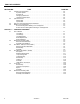
TABLE OF CONTENTS SECTION NO. TITLE PAGE NO. SECTION A - INTRODUCTION - MAINTENANCE SAFETY PRECAUTIONS A B C General . . . . . . . . . . . . . . . . . . . . . . . . . . . . . . . . . . . . . . . . . . . . . . . . . . . . . . . . . . . . . . . . . . . . . .A-1 Hydraulic System Safety . . . . . . . . . . . . . . . . . . . . . . . . . . . . . . . . . . . . . . . . . . . . . . . . . . . . . . . . .A-1 Maintenance . . . . . . . . . . . . . . . . . . . . . . . . . . . . . . . . . . . . . . . . . . . . . . . .
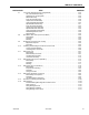
TABLE OF CONTENTS SECTION NO. 2.3 2.4 2.5 2.6 TITLE PAGE NO. Lubrication and Information . . . . . . . . . . . . . . . . . . . . . . . . . . . . . . . . . . . . . . . . . . . . . . . . . . . . . .2-4 Hydraulic System. . . . . . . . . . . . . . . . . . . . . . . . . . . . . . . . . . . . . . . . . . . . . . . . . . . . . . . . . . 2-4 Hydraulic Oil . . . . . . . . . . . . . . . . . . . . . . . . . . . . . . . . . . . . . . . . . . . . . . . . . . . . . . . . . . . . . 2-4 Changing Hydraulic Oil . . . . .
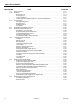
TABLE OF CONTENTS SECTION NO. 3.7 3.8 3.9 3.10 3.11 3.12 3.13 3.14 3.15 3.16 3121139 TITLE PAGE NO. Torque Hub (4WD Machines W/ Integral Brake) . . . . . . . . . . . . . . . . . . . . . . . . . . . . . . . . . . . . . .3-35 Roll, Leak and Brake Testing. . . . . . . . . . . . . . . . . . . . . . . . . . . . . . . . . . . . . . . . . . . . . . . . . 3-35 Tightening and Torquing Bolts . . . . . . . . . . . . . . . . . . . . . . . . . . . . . . . . . . . . . . . . . . . . . . . 3-35 Main Disassembly .
TABLE OF CONTENTS SECTION NO. 3.17 3.18 3.19 3.20 3.21 3.22 3.23 3.24 iv TITLE PAGE NO. Rotary Coupling . . . . . . . . . . . . . . . . . . . . . . . . . . . . . . . . . . . . . . . . . . . . . . . . . . . . . . . . . . . . . . .3-111 Generator. . . . . . . . . . . . . . . . . . . . . . . . . . . . . . . . . . . . . . . . . . . . . . . . . . . . . . . . . . . . . . . . . . . . .3-114 Every 250 hours . . . . . . . . . . . . . . . . . . . . . . . . . . . . . . . . . . . . . . . . . . . . . . . . . .
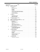
TABLE OF CONTENTS SECTION NO. TITLE PAGE NO. SECTION 4 - BOOM & PLATFORM 4.1 4.2 4.3 4.4 4.5 4.6 4.7 4.8 4.9 3121139 Boom Maintenance . . . . . . . . . . . . . . . . . . . . . . . . . . . . . . . . . . . . . . . . . . . . . . . . . . . . . . . . . . . . .4-1 Removal . . . . . . . . . . . . . . . . . . . . . . . . . . . . . . . . . . . . . . . . . . . . . . . . . . . . . . . . . . . . . . . . . 4-1 Boom Disassembly . . . . . . . . . . . . . . . . . . . . . . . . . . . . . . . . . . . . . . . . . .
TABLE OF CONTENTS SECTION NO. TITLE PAGE NO. SECTION 5 - HYDRAULICS 5.1 5.2 5.3 5.4 Lubricating O-Rings in the Hydraulic System. . . . . . . . . . . . . . . . . . . . . . . . . . . . . . . . . . . . . . . . .5-1 Cup and Brush. . . . . . . . . . . . . . . . . . . . . . . . . . . . . . . . . . . . . . . . . . . . . . . . . . . . . . . . . . . . 5-1 Dip Method . . . . . . . . . . . . . . . . . . . . . . . . . . . . . . . . . . . . . . . . . . . . . . . . . . . . . . . . . . . . . . 5-2 Spray Method . .
LIST OF FIGURES FIGURE NO. 1-1. 1-2. 1-3. 1-4. 1-5. 1-6. 1-7. 1-8. 1-9. 2-1. 2-2. 2-3. 2-4. 3-1. 3-2. 3-3. 3-4. 3-5. 3-6. 3-7. 3-8. 3-9. 3-10. 3-11. 3-12. 3-13. 3-14. 3-15. 3-16. 3-17. 3-18. 3-19. 3-20. 3-21. 3-22. 3-23. 3-24. 3-25. 3-26. 3-27. 3-28. 3-29. 3-30. 3-31. 3-32. 3121139 TITLE PAGE NO. Operator Maintenance and Lubrication Diagram . . . . . . . . . . . . . . . . . . . . . . . . . . . . . . . . . . . . . .1-6 Filter Lock Assembly . . . . . . . . . . . . . . . . . . . . . . . . . . . . . . . .
LIST OF FIGURES FIGURE NO. 3-33. 3-34. 3-35. 3-36. 3-37. 3-38. 3-39. 3-40. 3-41. 3-42. 3-43. 3-44. 3-45. 3-46. 3-47. 3-48. 3-49. 3-50. 3-51. 3-52. 3-53. 3-54. 3-55. 3-56. 3-57. 3-58. 3-59. 3-60. 3-61. 3-62. 3-63. 3-64. 3-65. 3-66. 3-67. 3-68. 3-69. 3-70. 3-71. 3-72. 3-73. viii TITLE PAGE NO. Spindle Brake Disassembly . . . . . . . . . . . . . . . . . . . . . . . . . . . . . . . . . . . . . . . . . . . . . . . . . . . . . .3-41 Input Carrier Sub-Assembly . . . . . . . . . . . . . . . . . . . . . . . . .
LIST OF FIGURES FIGURE NO. 3-74. 3-75. 3-76. 3-77. 3-78. 3-79. 3-80. 3-81. 3-82. 3-83. 3-84. 3-85. 3-86. 3-87. 3-88. 3-89. 3-90. 3-91. 3-92. 3-93. 3-94. 3-95. 3-96. 3-97. 4-1. 4-2. 4-3. 4-4. 4-5. 4-6. 4-6. 4-6. 4-7. 4-8. 4-9. 4-10. 4-11. 4-12. 4-13. 4-14. 4-15. 4-16. 4-17. 4-18. 4-19. 3121139 TITLE PAGE NO. EMR 2 Engine Plug Pin Identification . . . . . . . . . . . . . . . . . . . . . . . . . . . . . . . . . . . . . . . . . . . . . . .3-135 EMR 2 Vehicle Plug Pin Identification . . . . . . . . . . . .
LIST OF FIGURES FIGURE NO. 4-20. 4-21. 4-22. 4-23. 5-1. 5-2. 5-3. 5-4. 5-5. 5-6. 5-7. 5-8. 5-9. 5-10. 5-11. 5-12. 5-13. 5-14. 5-15. 5-16. 5-17. 5-17. 6-1. 6-2. 6-3. 6-4. 6-5. 6-6. 6-7. 6-8. 6-9. 6-10. 6-11. 6-12. 7-1. 7-2. 7-3. 7-4. 7-5. 7-6. 7-7. 7-8. 7-9. 7-10. 7-11. x TITLE PAGE NO. Rotary Actuator (Cutaway View) . . . . . . . . . . . . . . . . . . . . . . . . . . . . . . . . . . . . . . . . . . . . . . . . . . .4-40 Rotator Counterbalance Valve . . . . . . . . . . . . . . . . . . . . . . . . . . .
LIST OF FIGURES FIGURE NO. 7-12. 7-13. 7-14. 7-15. 7-16. 7-17. 7-18. 7-19. 7-20. 7-21. 7-22. 7-23. 7-24. 7-25. 7-26. 7-27. 7-28. 7-29. 7-30. 7-31. 7-32. 7-33. 7-34. 7-35. 3121139 TITLE PAGE NO. DT/DTP Contact Installation . . . . . . . . . . . . . . . . . . . . . . . . . . . . . . . . . . . . . . . . . . . . . . . . . . . . . .7-8 DT/DTP Contact Removal . . . . . . . . . . . . . . . . . . . . . . . . . . . . . . . . . . . . . . . . . . . . . . . . . . . . . . . .7-8 HD/HDP Contact Installation . . . .
LIST OF TABLES TABLE NO. 1-1 1-2 1-3 1-4 1-5 1-6 1-7 1-8 1-9 1-10 1-11 1-12 1-13 1-14 1-15 1-16 1-17 1-18 1-19 1-20 2-1 2-2 2-3 3-1 3-2 3-3 3-4 3-5 3-6 3-7 3-8 3-9 3-10 3-11 3-12 3-13 3-14 4-1 5-1 5-2 5-3 5-4 5-5 5-6 6-1 6-2 6-3 6-4 6-5 6-6 6-7 6-8 xii TITLE PAGE NO. Operating Specifications . . . . . . . . . . . . . . . . . . . . . . . . . . . . . . . . . . . . . . . . . . . . . . . . . . . . . . . . .1-1 Specifications and Performance Data . . . . . . . . . . . . . . . . . . . . . . . . . . . . . . .
SECTION 1 - SPECIFICATIONS SECTION 1. SPECIFICATIONS 1.1 OPERATING SPECIFICATIONS 1.2 Table 1-1. Operating Specifications Maximum Work Load (Capacity) Unrestricted: Restricted Maximum Capacity - Dual Rating 800S 860SJ Maximum Travel Grade (Gradeability)* 2WD 4WD Maximum Travel Grade (Side Slope)* Maximum Vertical Platform Height: Maximum Horizontal Platform Reach 800S 860SJ Turning Radius (outside) Table 1-2.
SECTION 1 - SPECIFICATIONS 1.3 CAPACITIES Table 1-5. Deutz F4M2011 Specifications Table 1-3. Capacities Fuel Tank Approx. 31 gallons (117 liters) Hydraulic Tank Approx. 47.8 gallons (181 liters) Engine Oil Capacity Ford Deutz Cooling System Crankcase Total Capacity Caterpillar GM 1.4 4.5 Quarts (4.25 L) w/Filter 5 Quarts (4.5 L) 11 Quarts (10.5 L) w/Filter 16 Quarts (15 L) 10.6 quarts (10 L) 4.5 Quarts (4.
SECTION 1 - SPECIFICATIONS 1.5 Table 1-7. Caterpillar 3044C/ Caterpillar 3.4 Type TIRES Table 1-10. Tire Specifications Four Stroke Cycle Cylinders 4 in-line Bore Stroke 15 - 625 Pneumatic 95 psi (6.5 Bar) 16 H 269 lbs. (122 kg) 15 - 625 Foam-Filled 16 H 544 lbs. (247 kg) 18 - 625 Pneumatic 85 psi (6.5 Bar) 16 H 288 lbs. (131 kg) 18 - 625 Foam-Filled 16 H 601 lbs. (273 kg) 41/ 18LL x 22.5 Foam-Filled 16 H 724 lbs.
SECTION 1 - SPECIFICATIONS Drive (Elevated): Test should be done on a smooth level surface. Drive Select Switch should be set to High Engine. Results should be recorded for a 50 ft. course. Drive Forward, Record Time. Drive Reverse, Record Time. 1.8 Hydraulic Oil Table 1-13. Hydraulic Oil Platform Rotate: Platform level and completely rotated one direction. Rotate the opposite direction, Record Time. Rotate the other direction, Record Time.
SECTION 1 - SPECIFICATIONS Table 1-15. Mobil DTE 13M Specs ISO Viscosity Grade #32 Specific Gravity 0.877 Pour Point, Max -40°F (-40°C) Flash Point, Min. 330°F (166°C) Viscosity 1.9 PRESSURE SETTINGS Table 1-18. Pressure Settings Telescope Out 2500 psi (172 Bar) Swing, Left & Right 1700 psi (117 Bar) Steer 2500 psi (172 Bar) Platform Level Up 2600 psi (179 Bar) at 40° C 33cSt Platform Level Down 1800 psi (124 Bar) at 100° C 6.
SECTION 1 - SPECIFICATIONS Figure 1-1. Operator Maintenance and Lubrication Diagram 1.11 OPERATOR MAINTENANCE NOTE: NOTE: The following numbers correspond to those in Figure 1-1., Operator Maintenance and Lubrication Diagram. It is recommended as a good practice to replace all filters at the same time. 1.Swing Bearing - Internal Ball Bearing Table 1-20. Lubrication Specifications KEY SPECIFICATIONS MPG Multipurpose Grease having a minimum dripping point of 350° F (177° C).
SECTION 1 - SPECIFICATIONS 2. Wheel Bearings 4. Hydraulic Return Filter Lube Point(s) - Repack Capacity - A/R Lube - MPG Interval - Every 2 years or 1200 hours of operation Interval - Change after first 50 hrs. and every 6 months or 300 hrs. thereafter or as indicated by Condition Indicator. 5. Hydraulic Charge Filter 3. Wheel Drive Hub Lube Point(s) - Level/Fill Plug Capacity - 17 oz. (0.
SECTION 1 - SPECIFICATIONS 9. Oil Change w/Filter - Ford 7. Platform Filter Interval - Change as necessary Lube Point(s) - Fill Cap/Spin-on Element Capacity - 4.5 Quarts Lube - EO Interval - 3 Months or 150 hours of operation Comments - Check level daily/Change in accordance with engine manual. 8. Suction Strainers 10. Oil Change w/Filter - Deutz Lube Point(s) - Fill Cap/Spin-on Element Capacity - 11 Quarts(10.
SECTION 1 - SPECIFICATIONS 12. Oil Change w/Filter - GM 14. Fuel Filter - Deutz Lube Point(s) - Fill Cap/Spin-on Element (JLG P/N 7027965) Capacity - 4.5 qt. (4.25 L) w/filter Lube - EO Interval - 3 Months or 150 hours of operation Comments - Check level daily/Change in accordance with engine manual. 13. Fuel Filter - Ford Lube Point(s) - Replaceable Element Interval - Every Year or 600 hours of operation 15.
SECTION 1 - SPECIFICATIONS Draining Oil Build Up From The Propane Regulator 18. Electronic Pressure Regulator (LP only) During the course of normal operation oils may build inside the primary and secondary chambers of the propane pressure regulator. These oils may be a result of poor fuel quality, contamination of the fuel supply chain, or regional variation in the make up of the fuel. If the build up of the oil is significant this can effect the operation of the fuel control system. Refer to Section 1.
SECTION 1 - SPECIFICATIONS 5. Disconnect the electrical connection to the LPG fuel temperature sensor in the auxiliary fuel port of the EPR. Propane Fuel Filter Replacement 6. Remove the retainer clip for the LPG fuel temperature sensor and remove the sensor from the regulator body. 1. 2. 3. 4. 5. 6. Electric Lock Off Solenoid Mounting Plate Housing Seal Filter Magnet Filter Housing Seal 7. 8. 9. 10. 11. 12. Electrical Connector Fuel Outlet O-ring Filter Fuel Inlet Retaining Bolt Figure 1-2.
SECTION 1 - SPECIFICATIONS Propane Fuel System Pressure Relief INSTALLATION BE SURE TO REINSTALL THE FILTER MAGNET INTO THE HOUSING BEFORE INSTALLING NEW SEAL 1. Install the mounting plate to lock off O-ring seal. 2. Install the retaining bolt seal. 3. Install the housing seal. THE PROPANE FUEL SYSTEM OPERATES AT PRESSURES UP TO 312 PSI (21.5 BAR).
SECTION 1 - SPECIFICATIONS Figure 1-4.
SECTION 1 - SPECIFICATIONS Figure 1-5.
SECTION 1 - SPECIFICATIONS Figure 1-6.
SECTION 1 - SPECIFICATIONS Figure 1-7.
SECTION 1 - SPECIFICATIONS Figure 1-8.
SECTION 1 - SPECIFICATIONS Figure 1-9.
SECTION 2 - GENERAL SECTION 2. GENERAL 2.1 MACHINE PREPARATION, INSPECTION, AND MAINTENANCE General This section provides the necessary information needed by those personnel that are responsible to place the machine in operation readiness and maintain its safe operating condition. For maximum service life and safe operation, ensure that all the necessary inspections and maintenance have been completed before placing the machine into service.
SECTION 2 - GENERAL Table 2-1. Inspection and Maintenance Primary Responsibility Service Qualification Reference Prior to use each day; or At each Operator change. User or Operator User or Operator Operation and Safety Manual Pre-Delivery Inspection Prior to each sale, lease, or rental delivery. Owner, Dealer, or User Qualified JLG Mechanic Service and Maintenance Manual and applicable JLG inspection form.
SECTION 2 - GENERAL Component Disassembly and Reassembly When disassembling or reassembling a component, complete the procedural steps in sequence. Do not partially disassemble or assemble one part, then start on another. Always recheck your work to assure that nothing has been overlooked. Do not make any adjustments, other than those recommended, without obtaining proper approval.
SECTION 2 - GENERAL 2.3 LUBRICATION AND INFORMATION Changing Hydraulic Oil 1. Filter elements must be changed after the first 50 hours of operation and every 300 hours (unless specified otherwise) thereafter. If it is necessary to change the oil, use only those oils meeting or exceeding the specifications appearing in this manual. If unable to obtain the same type of oil supplied with the machine, consult local supplier for assistance in selecting the proper equivalent.
SECTION 2 - GENERAL Cylinder Drift c. Rusting of the pin in the bearing area. 4. Re-assembly of pinned joints using filament wound bearings. Table 2-2. Cylinder Drift Cylinder Bore Diameter a. Housing should be blown out to remove all dirt and debris...bearings and bearing housings must be free of all contamination. Max. Acceptable Drift in 10 Minutes inches mm inches mm 3 76.2 0.026 0.66 3.5 89 0.019 0.48 4 101.6 0.015 0.38 5 127 0.009 0.22 6 152.4 0.006 0.15 7 177.8 0.
SECTION 2 - GENERAL Table 2-3.
SECTION 2 - GENERAL Table 2-3.
SECTION 2 - GENERAL Table 2-3.
SECTION 2 - GENERAL 4150548 D Figure 2-1.
SECTION 2 - GENERAL 4150548 D Figure 2-2.
SECTION 2 - GENERAL 4150548 D Figure 2-3.
SECTION 2 - GENERAL 4150548 D Figure 2-4.
SECTION 3 - CHASSIS & TURNTABLE SECTION 3. CHASSIS & TURNTABLE Tire Replacement 3.1 TIRES & WHEELS Tire Inflation The air pressure for pneumatic tires must be equal to the air pressure that is stenciled on the side of the JLG product or rim decal for safe and proper operational characteristics. JLG recommends a replacement tire be the same size, ply and brand as originally installed on the machine.
SECTION 3 - CHASSIS & TURNTABLE Wheel Installation 3.2 WHEEL DRIVE ASSEMBLY, 2WD It is extremely important to apply and maintain proper wheel mounting torque. WHEEL NUTS MUST BE INSTALLED AND MAINTAINED AT THE PROPER TORQUE TO PREVENT LOOSE WHEELS, BROKEN STUDS, AND POSSIBLE DANGEROUS SEPARATION OF WHEEL FROM THE AXLE. BE SURE TO USE ONLY THE NUTS MATCHED TO THE CONE ANGLE OF THE WHEEL. Tighten the lug nuts to the proper torque to prevent wheels from coming loose.
SECTION 3 - CHASSIS & TURNTABLE Figure 3-1. Torque Hub Installation - 2WD Assembly and Installation 1. If re-installing the old studs or installing new ones, coat the threads of the studs with Loctite #242 before screwing them into the torque hub. 2. Install a new o-ring between the drive brake and torque hub and slide the drive brake over the studs with the brake port positioned as shown. 3. Install a new o-ring between the drive brake and drive motor and slide the drive motor over the studs.
SECTION 3 - CHASSIS & TURNTABLE 3.3 DRIVE MOTOR - 2WD (PRIOR TO S/N 83331) Replacing the Drive Shaft Seal 1. Remove snap ring. 5. Assemble the snap ring. 2. Change the shaft seal and check its sliding surface (drive shaft) and housing, grease the sealing ring. 6. Assemble the snap ring in the correct position. 3. Be careful while you seal the drive shaft, use an adhesive tape. NOTE: This description shows how to change the drive shaft sealing ring but isn’t the way of serial assembly.
SECTION 3 - CHASSIS & TURNTABLE Disassembly 4. Remove the O-ring. 1. Disassemble the pilot valve. 5. Disassemble the taper roller bearing (near by port plate). 2. Mark the position of the port plate and remove the socket screw of the port plate. 6. Remove the adjustment shim. 3. Remove the port plate together with the valve plate (hold the valve plate so that the plate can’t fall down).
SECTION 3 - CHASSIS & TURNTABLE 7. Unscrew the cap nut and remove it. 10. Disassemble the rotary group in horizontal position. 8. Loosen the fixing nut of the stopper max flow and disassemble it. 11. Disassemble the stopper - max flow. 12. Remove the threaded pin (stopper - max flow). 9. Turn in the stopper max flow to get swivel angle zero. 13. Disassemble the plug.
SECTION 3 - CHASSIS & TURNTABLE 14. Disassemble the control plate while moving the swash plate. 17. Remove the spring. 18. Remove both bearing shells. 15. The swash plate must be lifted a little bit to disassemble the piston rod. 19. Remove the drive shaft. 16. Disassemble the swash plate. 20. Disassemble the snap ring.
SECTION 3 - CHASSIS & TURNTABLE 21. Disassemble the sealing ring. bearing inside the port plate. Take care of the surface of the port plate. 22. The external front bearing ring is pulled out of the pump housing. 25. The spring has additional pretension while you disassemble the three pressure pins inside the cylinder. 23. Remove the O-ring. Lifting of the valve plate isn’t shown. 24.
SECTION 3 - CHASSIS & TURNTABLE Assembly 4. Pumps anti-clockwise driven must have a position of the valve plate 4° decentered in counter-clockwise position. 1. Assemble the variable displacement pump in reverse order. 2. Measurement of the taper roller bearing pretension (see adjustment figure). 5. Assembly of the port plate and pump housing: NOTE: There is a correct connection of the piston rod and swash plate.
SECTION 3 - CHASSIS & TURNTABLE Figure 3-2.
SECTION 3 - CHASSIS & TURNTABLE 3.4 DRIVE MOTOR (S/N 83331 TO PRESENT) Shaft Seal Replacement REMOVAL Description 1. Remove the snap ring (1) retaining the shaft seal and support washer. The drive motors are low to medium power, two-position axial piston motors incorporating an integral servo piston. They are designed for operation in both open and closed circuit applications. The standard control is a direct acting single line hydraulic control. The integral servo piston controls motor displacement.
SECTION 3 - CHASSIS & TURNTABLE Loop Flushing Valve INSPECT THE COMPONENTS REMOVAL 1. Using a 11/16 in internal hex wrench remove plug (1) and (2). Inspect new O-rings and the sealing area for rust, wear, or contamination. Also check springs and poppet for wear. 1. Install orifice poppet (13). 6 9 11 INSTALLATION 2. Install shift spool (12). 2 11/16 in 27 ft.lbs. (37 Nm) 3. Install spring retaining washers onto springs (10 and 11). 4. Carefully install centering springs (7, 8, and 9). 5.
SECTION 3 - CHASSIS & TURNTABLE Troubleshooting Table 3-2. Excessive Noise and/or Vibration Item Description Action Check oil level in reservoir and oil supply to the motor. Insufficient hydraulic fluid could lead to cavitation that would cause system noise. Fill the reservoir to the proper level and ensure that oil supply to the motor is adequate and the lines are unobstructed. Check for air in the system.
SECTION 3 - CHASSIS & TURNTABLE Disassembly 17 NOTE: Removal of the endcap voids warranty. 19 During assembly, coat all moving parts with a film of clean hydraulic oil. This assures that these parts will be lubricated during start-up. 15 Replace all O-Rings and gaskets. 14 It is recommended that all O-rings be replaced. Lightly lubricate all O-rings with clean petroleum jelly prior to assembly. 21 6 9 11 5 7 2 18 13 3 10 8 4 12 16 16 1 20 14. 15. 16. 17.
SECTION 3 - CHASSIS & TURNTABLE 25 22 27 30 29 23 26 24 29 28 22. Screw 23. End Cap 24. O-ring 25. 26. 27. 28. 29. 30. Figure 3-8. End Cap 13. Using an 8 mm internal hex wrench, remove the endcap screws (22). Valve Plate End Cap O-ring O-ring Angle Stop Servo Spring Figure 3-9. Valve Plate & Rear Shaft Bearing 14. Remove the endcap (23). Remove O-ring (24) from the housing or endcap. When the endcap screws are removed, pressure from the servo spring will cause the endcap to bind on the shaft.
SECTION 3 - CHASSIS & TURNTABLE 18. Remove minimum angle stop (29) and servo spring (30) from the housing. shaft seal (34). Discard the seal. To avoid damaging the shaft during seal removal, install a large sheet metal screw into the chuck of a slide hammer. Drive the screw into the seal surface and use the slide hammer to pull the seal. 31 36 35 37 38 31. Cylinder Kit Assembly Figure 3-10. Cylinder Kit 19. Turn the housing on its side and remove the cylinder kit assembly (31).
SECTION 3 - CHASSIS & TURNTABLE Lift here 44 39 45 47 40 48 43 42 49 41 46 53 52 39. 40. 41. 42. 43. Swashplate Servo Piston Piston Seal O-ring Journal Bearings 50 51 Figure 3-13. Swash Plate & Servo Piston 44. 45. 46. 47. 48. 23. Turn housing over and remove the swashplate (39) by lifting on the end opposite the servo lever. 24. Remove the servo piston (40). Remove the piston seal (41) and O-ring (42) from the servo piston. Discard the seal and O-ring. 25.
SECTION 3 - CHASSIS & TURNTABLE SLIPPERS 28. Turn the block over. Using a press, apply pressure on the block spring washer (50) to compress the block spring. Compress the spring enough to safely remove the spiral retaining ring (51). While maintaining pressure, unwind the spiral retaining ring (51). Carefully release the pressure and remove the outer block spring washer (50), block spring (52), and inner block spring washer (53) from the cylinder block. Inspect the running surface of the slippers.
SECTION 3 - CHASSIS & TURNTABLE BALL GUIDE AND SLIPPER RETAINER Inspect the ball guide and slipper retainer for damage, discoloration, or excessive wear. A discolored ball guide or slipper retainer indicates excessive heat. Do not reuse. Replace swashplate if the difference in thickness from one side to the other exceeds specification. 0.0025 mm [0.0001 in] Slipper retainer 25.8 mm LV [1.015 in] mm KV 24.6 [0.969 in] Ball guide Thickness equality side to side: 0.05 mm [0.
SECTION 3 - CHASSIS & TURNTABLE SERVO PISTON AND MINIMUM ANGLE STOP Assembly Inspect the minimum angle stop, servo piston head, and servo piston ball-socket for damage or excessive wear. Replace if necessary. 1. Install new O-ring (1) and piston seal (2) to the servo piston (3). Install the piston seal over the O-ring. Installing the piston seal stretches it, making it difficult to install the servo piston in its bore. Allow 30 minutes for the seal to relax after installation.
SECTION 3 - CHASSIS & TURNTABLE RISK OF PERSONAL INJURY: COMPRESSING THE BLOCK SPRING REQUIRES ABOUT 80 TO 90 LBF (350 TO 400 N) OF FORCE. USE A PRESS SUFFICIENT TO MAINTAIN THIS FORCE WITH REASONABLE EFFOR T. ENSURE THE SPRING IS SECURE BEFORE ATTEMPTING TO INSTALL THE SPIRAL RETAINING RING. RELEASE THE PRESSURE SLOWLY AFTER THE RETAINING RING IS INSTALLED. 3. Install the inner block spring washer (4), block spring (5), and outer washer (6) into the cylinder block.
SECTION 3 - CHASSIS & TURNTABLE 8. Press front shaft bearing (15) onto shaft (16). Press bearing onto shaft with lettering facing out. Lubricate bearing rollers. Install snap-ring (17) onto shaft. 10. Verify swashplate and bearings are properly seated. Install the cylinder kit (19) onto the shaft. Install with the slippers facing the swashplate. Rock the shaft to align the block splines and slide the cylinder kit into place.
SECTION 3 - CHASSIS & TURNTABLE 12. Press the rear shaft bearing (22) into the endcap. Install the bearing with letters facing out. Press until bearing surface is 0.08 ±0.01 in (2 ±0.25 mm) above endcap surface. 22 2 mm [0.08 in] 23 3 mm [0.12 in] 15. Install the endcap (25) onto the housing with the endcap screws (26). Check to ensure the endcap will properly seat onto the housing without interference. Improper assembly of the internal components may prevent the endcap from seating properly.
SECTION 3 - CHASSIS & TURNTABLE 18. Cover shaft splines with an installation sleeve. Install a new shaft seal (27) with the cup side facing the motor. Press seal into housing until it bottoms out. Press evenly to avoid binding and damaging the seal. Install seal support washer (28) and snap ring (29). 19. Install remaining plugs and fittings to the housing. Refer to the drawing below for wrench sizes and installation torques. 5/16 in 63 ft.lbs. (85 Nm) 1/4 in 33 ft.lbs.
SECTION 3 - CHASSIS & TURNTABLE Initial Start-up Procedures 20. Install orifice poppet (30). Follow this procedure when starting-up a new motor or when installing a motor that has been removed. 37 36 33 39 41 34 11/16 in 30 27 ft.lbs. (37 Nm) 40 5/8 in 20 ft.lbs. (27 Nm) 32 35 38 Prior to installing the motor, inspect for damage incurred during shipping. Make certain all system components (reservoir, hoses, valves, fittings, heat exchanger, etc.) are clean prior to filling with fluid. 1.
SECTION 3 - CHASSIS & TURNTABLE Cleaning and Inspection 3.5 TORQUE HUB 1. Thoroughly clean all parts in an approved cleaning solvent. Disassembly 1. Position hub over suitable container and remove drain plugs (10) from unit. Allow oil to completely drain, then replace drain plugs. 2. Remove eight bolts (41) and four shoulder bolts (42) securing cover assembly to hub (7). Remove cover assembly (23) and discard o-ring seal (22). 3.
SECTION 3 - CHASSIS & TURNTABLE Repair 1. Cover Assembly. a. Remove two bolts (25) securing disconnect cap (26) to cover (23) and remove cap. b. Remove two bolts (25) securing cover cap (24) to cover and remove cap. c. Remove disconnect rod (27) from cap and remove o-rings (28, 29) from cover cap. Discard o-rings. d. If necessary, remove pipe plug (30) from cover. e. Clean and inspect parts in accordance with Cleaning and Inspection procedures. Replace parts as necessary. i.
SECTION 3 - CHASSIS & TURNTABLE p. repeat steps (h) through (o) for remaining two cluster gears. m. While keeping thrust washers in place, slide cluster gear into carrier with larger gear on side with small pin hole. 3. Input Shaft Assembly. EYE PROTECTION SHOULD BE WORN DURING RETAINING RING REMOVAL AND INSTALLATION a. Carefully remove retaining ring (33) from counterbore in the spindle (1) and discard retaining ring. b. Remove two spacers (31) and spring (32) from input shaft. 3-28 c.
SECTION 3 - CHASSIS & TURNTABLE 4. Lower hub onto spindle (1) with large open end up. Assembly . 1. Using a suitable press, press new bearing cups (3, 5), with large inside diameters facing out, into hub (7) counter bores. 5. Place bearing cone (6) over end of spindle and into bearing cup. 2. Place bearing cone (4) into bearing cup (3) in small end of hub. 6. Place bearing shim (8) over end of spindle and against bearing cone. 3.
SECTION 3 - CHASSIS & TURNTABLE EYE PROTECTION SHOULD BE WORN DURING RETAINING RING INSTALLATION. 7. Install new retaining ring (9) completely into spindle groove and against bearing shim. Ensure retaining ring is entirely in groove. 11. Place input shaft assembly (35) into spindle bore with unsplined end facing out. 8. Place internal gear (12) onto end of spindle. 12. Place thrust spacer (36) over input shaft (35) with counter bore side facing spindle. 9.
SECTION 3 - CHASSIS & TURNTABLE 14. Place o-ring (22) into hub counter bore. Use petroleum or grease to hold o-ring in place. Slight stretching of o-ring may be necessary to insure proper seating. NOTE: If gears do not mesh easily or carrier assembly does not rotate freely, then remove carrier and ring gear and check cluster gear timing. 15. Place carrier assembly on a flat surface with large gears up and positioned as shown.
SECTION 3 - CHASSIS & TURNTABLE 21. Place o-ring (22) into cover assembly counter bore. Use petroleum jelly or grease to hold o-ring in place. 22. Place cover assembly over ring gear with oil level check plug in cover located approximately 90 degrees from oil fill plug in hub. 25. Place coupling (1) into spindle and onto input shaft. 26. Fill hub one-half full of EPGL 90 lubricant before operation. 23.
SECTION 3 - CHASSIS & TURNTABLE 1. 2. 3. 4. 5. 6. 7. 8. 9. 10. 11. 12. 13. 14. 15. 16. 17. 18. 19. 20. 21. 22. 23. 24. 25. 26. 27. 28. 29. 30. 31. 32. 33. 34. 35. 36. 37. 38. 39. 40. 41. 42. 43.
SECTION 3 - CHASSIS & TURNTABLE NOTE: The torque hub and drive motor assembly weighs approximately 270 lbs. (122 kg). 3.6 WHEEL DRIVE ASSEMBLY, 4WD Removal and Disassembly 4. Use a supporting device capable of handling the weight of the torque hub and drive motor and unbolt the torque hub from the frame. Remove the entire assembly from the machine.
SECTION 3 - CHASSIS & TURNTABLE Tightening and Torquing Bolts 3.7 TORQUE HUB (4WD MACHINES W/ INTEGRAL BRAKE) If an air impact wrench is used to tighten bolts, extreme care should be taken to ensure that the bolts are not tightened beyond their specified torque. Roll, Leak and Brake Testing Torque-Hub units should always be roll and leak tested before disassembly and after assembly to make sure that the unit's gears, bearings and seals are working properly.
SECTION 3 - CHASSIS & TURNTABLE Main Disassembly 9. Remove Input Shaft (7) from Output Carrier SubAssembly (4A). 1. Perform Roll Check, Leak Check and Brake Check if applicable prior to disassembling the unit. 10. Remove Output Carrier Sub-Assembly (4A) from Housing (1E). 2. Drain oil from unit. Note the condition and volume of the oil. 3. Remove Input Coupling (9) from Spindle (1A) end of unit. 4. Remove Cover Bolts (14) and remove Cover (6). 5.
SECTION 3 - CHASSIS & TURNTABLE 7. Input Shaft 8. Output Sun Gear 17. Input Sun Gear Figure 3-29.
SECTION 3 - CHASSIS & TURNTABLE Input Carrier Disassembly 1. Place the Carrier (3A) on a press with the spline end up and drive the Planet Shaft (3E) out of the Carrier (3A). 2. Slide the Planet Gear (3F) and the two Thrust Washers (3B) out of the Carrier (3A). 3. Remove the 14 needle Bearings (3C) from the bore of the Planet Gear (3F). 4. Repeat steps 1 through 3 for each of the two remaining planet gears. 3A. 3B. 3C. 3E. 3F. Carrier Thrust Washers Needle Bearings Planet Shaft Planet Gear Figure 3-30.
SECTION 3 - CHASSIS & TURNTABLE Output Carrier Disassembly 4. Remove the 15 needle Bearings (4C) from the bore of the Planet Gear (4F). 1. Using a small diameter punch, Drive the Roll Pin (4G) which holds the Planet Shaft (4E) in the Carrier (4A) down into the Planet Shaft (4E) until it bottoms. 5. Repeat steps 1 through 4 for each of the two remaining planet gears. 6. Remove the Thrust Washer (4H) from the Carrier (4A). NOTE: Make sure that the Roll Pin has bottomed.
SECTION 3 - CHASSIS & TURNTABLE Housing-Spindle Disassembly 6. Lift Housing (1E) off of Spindle (1A). 7. If necessary, press Studs (1N) out of Housing (1E). Locate Housing (1E) on Seal (1B) end. 1. Place unit on bench with Spindle (1A) end down. 8. Remove “B” position Bearing Cone (1D) from Spindle (1A). EYE PROTECTION MUST BE WORN WHILE PERFORMING THE NEXT STEP IN THIS PROCEDURE. 9. Remove Seal (1B) from the Spindle (1A). 10.
SECTION 3 - CHASSIS & TURNTABLE Spindle-Brake Disassembly NOTE: This procedure applies only to units with integral input brake (2). NOTE: For this procedure, use the Brake Assembly Drawing, which will show the proper balloon numbers for the individual brake components. In the following instructions, if the number has a “-” between two numbers, it refers to the Brake Assembly Drawing only and NOT the Torque Hub Assembly Drawing. 1-A. 12. 2-1. 2-2. 2-3. 2-4. 2-5. 2-6.
SECTION 3 - CHASSIS & TURNTABLE 1. Compress the Compression Springs (2-13) by installing a minimum of three M4 x 16mm Socket Head Cap Screws (2-11) equally spaced through End Plate (2-7) and into Piston (2-8) and tightening incrementally until spring force has been taken off of the Retaining Ring (2-6). 3. Set Carrier (3A) in an upright position. 4. Insert a Planet Shaft (3E) into the planet shaft hole in the end of the Carrier (3A) opposite the splined end. 5.
SECTION 3 - CHASSIS & TURNTABLE 3A. 3B. 3C. 3E. 3F. Carrier Thrust Washers Needle Bearings Planet Shaft Planet Gear Figure 3-34.
SECTION 3 - CHASSIS & TURNTABLE Output Carrier Sub-Assembly 8. Insert a Planet Shaft (4E) into one of the planet shaft holes on the Carrier (4A). The end of the planet shaft that does NOT have the roll pin hole should be inserted in the carrier FIRST. 1. Place Spring (4I) into the deep counterbore of the Output Carrier (4A). 2. Place Washer (4J) on top of Spring (4I). 9. Place one Thrust Washer (4B) onto the end of Planet Shaft (4E).
SECTION 3 - CHASSIS & TURNTABLE 4A. 4B. 4C. 4E. 4F. 4G. 4H. 4I. 4J. 4K. Output Carrier Thrust Washer Needle Rollers Planet Shaft Planet Gear Roll Pin Thrust Washer Spring Washer Retaining Ring Figure 3-35.
SECTION 3 - CHASSIS & TURNTABLE Spindle-Brake Sub-Assembly NOTE: This procedure applies only to units with integral input brake (2). NOTE: For this procedure, use the Brake Assembly Drawing (Figure 3-36.), which will show the proper balloon numbers for the individual brake components. In the following instructions, if the number has a “-” between two numbers, it refers to the Brake Assembly Drawing only and NOT the Torque Hub Assembly Drawing.
SECTION 3 - CHASSIS & TURNTABLE 1-A. 12. 2-1. 2-2. 2-3. 2-4. 2-5. 2-6. Spindle Pressure Plug Internal Circlip O-ring Back-up Ring O-ring Back-up Ring Internal Circlip 2-7. End Plate 2-8. Piston 2-9. Stator 2-10. Spacer 2-11. Capscrew 2-12. Rotor 2-13. Compression Spring Figure 3-36.
SECTION 3 - CHASSIS & TURNTABLE Housing-Spindle Sub-Assembly 8. Place Bearing Spacer (1F) on top of Bearing Cone (1D). NOTE: Spray a light film of oil on all component parts during assembly. SAFETY GLASSES MUST BE WORN DURING THE ENTIRE HOUSING-SPINDLE SUBASSEMBLY. 1. Press Bearing Cup (1C), position A, into Housing (1E) using appropriate pressing tool (See back of manual). 2. Turn Housing (1E) over and place into pressing base. Press nine Studs (1H) into Housing (1E). 9.
SECTION 3 - CHASSIS & TURNTABLE 1B. 1C. 1D. 1E. Seal Bearing Cups Bearing Cone Housing 1F. 1G. 1H. Bearing Spacer Retaining Ring Wheel Stud Figure 3-37.
SECTION 3 - CHASSIS & TURNTABLE Main Assembly 5. Place Input Carrier Sub-Assembly (3A) onto Output Sun Gear (8) splines. NOTE: All components should receive a generous amount of lubricant oil as they are being assembled. 1. Place Housing-Spindle Sub-Assembly on the bench with Spindle (1A) side down. 2. Place Output Carrier Sub-Assembly into Housing (1E) and onto Spindle (1A). 3.
SECTION 3 - CHASSIS & TURNTABLE 6. 9. 10. 14. 19. Cover Input Coupling Thrust Spacer Cover Bolts O-ring Figure 3-39.
Figure 3-40.
3121139 – JLG Lift – Retaining Ring - Ext Pressure Plug O-ring Pipe Plug Thrust Washer Housing/Ring Gear Stud Tapered Bearing - Cup Tapered Bearing - Cone Lip Seal Carrier Planet Gear Planet Shaft Needle Bearing Thrust Washer Carrier Planet Gear 1G 12 16 1F 1E 1N 1C 1D 1B 3A 3F 3E 3C 3B 4A 4F Sun Gear Sun Gear Input Shaft Coupling Cover Subassembly Thrust Spacer Id Plate 12 Pt Flange Bolt O-ring 8 7 9 6 10 15 14 19 Thrust Washer 4H 17 Thrust Washer 4B Thrust Washer Roll Pin 4G 4J Spring Retaini
Figure 3-42.
3121139 – JLG Lift – Input Brake Retaining Ring - Ext Pressure Plug O-ring Pipe Plug Thrust Washer Housing/ring Gear Stud Tapered Bearing - Cup Tapered Bearing - Cone Lip Seal Carrier Planet Gear Planet Shaft Needle Bearing Thrust Washer Carrier Planet Gear 2 1G 12 16 1F 1E 1N 1C 1D 1B 3A 3F 3E 3C 3B 4A 4F Spring Retaining Ring - Int Roll Pin Thrust Washer Thrust Washer Thrust Washer Sun Gear Sun Gear Input Shaft Coupling Cover Subassembly Thrust Spacer Id Plate 12 Pt Flange Bolt O-ring 4I 4G 4B 4H 4J
Figure 3-44.
Figure 3-45.
Figure 3-46.
Figure 3-47.
Figure 3-48.
Figure 3-49.
SECTION 3 - CHASSIS & TURNTABLE 3.8 DRIVE BRAKE, 2WD - MICO (PRIOR TO S/N 83331) NOTE: Cover plate (16) must be supported as indicated in Figure 1. 4. Install retaining ring (20) in cover plate (16). Disassembly 1. Remove pressure plate (3) from cover plate (16) by removing cap screws (1) and washers (2). PRESSURE PLATE IS UNDER SPRING TENSION OF APPROXIMATELY 907 KGF (2000 IBS). THE TWO CAP SCREWS MUST BE LOOSENED EVENLY TO RELIEVE THIS FORCE.
SECTION 3 - CHASSIS & TURNTABLE 1. 2. 3. 4. 5. 6. 7. Capscrew Washer Pressure Plate Case Seal O-ring Backup Ring Piston 8. 9. 10. 11. 12. 13. 14. O-ring Backup Ring Shaft Stator Disc Rotor Disc Return Plate Springs 15. 16. 17. 18. 19. 20. Dowel Pin Cover Plate Oil Seal Bearing Retaining Ring Retaining Ring Figure 3-50.
SECTION 3 - CHASSIS & TURNTABLE Bleeding top port. Pressure should not exceed 6.9 bar (100 psi) during bleeding. 1. Install brake in system and connect pressure lines. 3. Apply sufficient pressure to release brake and check for proper operation in system. 2. Bleed pressure release section of brake by pressurizing side inlet port and allowing air to escape from Table 3-8.
SECTION 3 - CHASSIS & TURNTABLE connecting the brake solenoid on the dual select valve. 3.9 RE-ALIGNING TORQUE HUB INPUT COUPLING The following procedure applies to torque hubs with integral brakes. Equipment Required 1. Hydraulic power supply (hand pump) capable of producing 200 psi (13.8 bar). 2. Hydraulic fittings to adapt hydraulic supply to brake release port on hub. Procedure 1. Using appropriate fittings, connect a line from the hydraulic power supply to the brake port. 2.
SECTION 3 - CHASSIS & TURNTABLE Oscillating Axle Lockout Test 7. Have an assistant check to see that left front wheel remains locked in position off of ground. 8. Carefully activate SWING control lever and return boom to stowed position (centered between drive wheels). When boom reaches center, stowed position, lockout cylinders should release and allow wheel to rest on ground, it may be necessary activate DRIVE to release cylinders.
SECTION 3 - CHASSIS & TURNTABLE 3.11 SWING DRIVE HUB WHEN REBUILDING OR REPAIRING THE UNIT, THE RETAINING RING (1I), O-RINGS (5) AND SEAL (1B) SHOULD ALWAYS BE REPLACED. Disassembly 1. Loosen all 12 cover bolts (12)&(13) and drain the oil from the unit. Main Assembly Procedure 2. Remove the 12 cover bolts (12)& (13) and lift off the cover (6). Remove and discard the O-ring (5) from the counterbore of the cover (6). 3. Remove the input gear (8) and thrust washer (10). 1.
SECTION 3 - CHASSIS & TURNTABLE 3. Place O-ring (5) into hub counterbore. Use petroleum jelly to hold O-ring in place. Also at this time locate and mark the 4 counter beamed holes in the face of the hub (1G). This is for identification later in the assembly. 6. With shoulder side of ring gear (4) facing down, place ring gear over (into mesh with) large gears. Be sure that punch marks remain in correct location during ring gear installation. The side of the ring gear with an x stamped on it should be up.
SECTION 3 - CHASSIS & TURNTABLE 8. Input gear (8) is installed, meshing with teeth of the large diameter cluster gear (3F). The counterbore on the input gear (8) locates on the shoulder of the thrust spacer (9). This is to be a slip fit and operate freely. 9. Thrust washer (10) is installed onto the input gear (8) and should locate on the gear teeth shoulder. BEWARE OF SHARP EDGES OF THE COUNTERBORE WHILE SEATING THIS O-RING. 12. THe cover (6) is now installed on this assembly.
SECTION 3 - CHASSIS & TURNTABLE 14. Pipe plugs (20) are to be installed into cover (6) using a lubricant of some sort. 2. Press bearing cup (1C) into hub (1G) taking care to insure cup start square with the bore of the hub. 15. Torque shoulder bolts (13) to 23-27 ft./lbs. and regular grade 8 bolts (12) to 23-27 ft./lbs, 3. Invert hub (1G) and press bearing cup (1E) into inter counterbore of hub (1G). This completes the assembly.
SECTION 3 - CHASSIS & TURNTABLE 5. The shaft seal (1B) is installed over the output shaft (1A) and into the counterbore of the hub (1G). Care should be taken to insure the seal (1B) is being correctly installed (smooth face up and located just flush with the counterbore face). 8. Bearing spacer (1H) is installed around the output shaft (1A) and locates on bearing cone (1F). 9. Retaining ring (1I) installed into groove provided in the output shaft (1A).
SECTION 3 - CHASSIS & TURNTABLE 10. A soft metal punch should be used to insure that this retaining ring (1I) is completely seated in the groove of the output shaft (1A). Carrier Sub-Assembly 1. Apply a coat of grease or petroleum jelly to cluster gear bore. EYE PROTECTION SHOULD BE WORN DURING THIS PROCEDURE. 2. Place sixteen needle rollers into cluster gear bore. 11. Upon completion of step 10, rap the internal end of the output shaft (1A) twice with a piece of soft metal rod.
SECTION 3 - CHASSIS & TURNTABLE 4. Place second set of sixteen needle rollers into cluster gear. 5. Apply grease or petroleum jelly to the tang side of two thrust washers. Place thrust washers against bosses in carrier with washer tang fitting into slot in carrier outside diameter. NOTE: Some old style carriers will not have slots and tangs should be located inside boss relief. 7. Line up cluster gear and thrust washer with hole in carrier and slide planet shaft through.
Figure 3-51.
SECTION 3 - CHASSIS & TURNTABLE 3.12 SWING BRAKE - MICO (PRIOR TO S/N 66417) NOTE: Cover plate (16) must be supported as indicated in Figure 1. 4. Install retaining ring (20) in cover plate (16). Disassembly 1. Remove pressure plate (3) from cover plate (16) by removing cap screws (1) and washers (2). PRESSURE PLATE IS UNDER SPRING TENSION OF APPROXIMATELY 907 KGF (2000 IBS). THE TWO CAP SCREWS MUST BE LOOSENED EVENLY TO RELIEVE THIS FORCE.
SECTION 3 - CHASSIS & TURNTABLE 1. 2. 3. 4. 5. 6. 7. Capscrew Washer Pressure Plate Case Seal O-ring Backup Ring Piston 8. 9. 10. 11. 12. 13. 14. O-ring Backup Ring Shaft Stator Disc Rotor Disc Return Plate Springs 15. 16. 17. 18. 19. 20. Dowel Pin Cover Plate Oil Seal Bearing Retaining Ring Retaining Ring Figure 3-52.
SECTION 3 - CHASSIS & TURNTABLE Bleeding top port. Pressure should not exceed 6.9 bar (100 psi) during bleeding. 1. Install brake in system and connect pressure lines. 3. Apply sufficient pressure to release brake and check for proper operation in system. 2. Bleed pressure release section of brake by pressurizing side inlet port and allowing air to escape from Table 3-9.
SECTION 3 - CHASSIS & TURNTABLE 4. Remove seal from end cap. 3.13 SWING MOTOR (PRIOR TO S/N 66417) Disassembly Cleanliness is extremely important when repairing these motors. Work in a clean area. Before disconnecting lines, clean port area of motor. Remove key when used. Check shaft and key slot. Remove burrs, nicks and sharp edges. Before disassembly, drain oil from motor. Then plug ports and thoroughly clean exterior of motor.
SECTION 3 - CHASSIS & TURNTABLE 13. Reposition motor in vise. Clamp across ports as shown above. Do not clamp side of housing. Excessive clamping pressure on side of housing causes distortion. 14. Remove cap screws from mounting flange. These screws are assembled with Loctite to hold them in place. The screws will require 35-45 Nm (300 - 400 in/lbs) of torque to break loose and 11 Nm (100 in/lbs) torque to remove. Do not use impact wrench on screws that have been secured with Loctite.
SECTION 3 - CHASSIS & TURNTABLE Check around key slot and chamfered area of shaft for burrs, nicks or sharp edges that could damage seals during reassembly. Remove nicks or burrs with hard smooth stone (such as an Arkansas stone). Do not file or grind motor parts. NOTE: Lubricate all seals with petroleum jelly. Use new seals when reassembling motor. DO NOT STRETCH SEALS BEFORE INSTALLING THEM. Cleanliness is extremely important in the successful application of Loctite.
SECTION 3 - CHASSIS & TURNTABLE 4. Install exclusion seal in flange. Carefully press exclusion seal into place. 5. Visually check seal seat in mounting flange for scratches or other marks that might damage the pressure seal. Check for cracks in flange that could cause leakage. 6. Lubricate I.D. of seal tube and O.D. of shaft pressure seal with light film of petroleum jelly. Align small I.D. end of seal tube with seal seat in mounting flange.
SECTION 3 - CHASSIS & TURNTABLE TO AID INSTALLATION OF SEALS, APPLY LIGHT COAT OF CLEAN PETROLEUM JELLY TO SEALS. DO NOT STRETCH SEALS BEFORE INSTALLING THEM IN GROOVE. 2. Pour approximately 35 cc of clean hydraulic oil in output shaft cavity. 3. Install 73 mm (2.875 in.) I.D. seal in housing seal groove. Avoid twisting seal. Timing Procedure a. Install drive. Use felt tip marker to mark or drive tooth. Align this tooth with timing dot on shaft.
SECTION 3 - CHASSIS & TURNTABLE Reverse rotation align any star valley with marked tooth (see figure below). 1. Rotate gerotor to line up with bolt holes. Be careful not to disengage star from drive or disturb gerotor seal. 4. Install cap screws and seal washers (if applicable) in end cap. Pre-tighten screws to 7.4 Nm (40 in/lbs). Make sure seal washers are properly seated. Then torque screws to 27 - 28 Nm (235 - 250 in/lbs) in sequence, as shown above. 2. Install drive spacer if applicable. 3.
SECTION 3 - CHASSIS & TURNTABLE 1. 2. 3. 4. 5. 6. 7. 8. 9. 10. 11. 12. 13. 14. Capscrew Exclusion Seal Mounting Flange Backup Ring (-008, -009 Motors) Pressure Seal Seal Bearing Race Needle Bearing Thrust Output Shaft Seal Washer (When Applicable) Capscrew Plug/O-ring S/A End Cap Seal 15. 16. 17. 18. 19. 20. 21. 22. 23. 24. 25. 26. 27. 28.
SECTION 3 - CHASSIS & TURNTABLE 3.14 SWING MOTOR (S/N 66417 TO PRESENT) Disassembly and inspection 1. Place the Torqlink™ in a soft jawed vice, with coupling shaft (12) pointed down and the vise jaws clamping firmly on the sides of the housing (18) mounting flange or port bosses. Remove manifold port O-Rings (18A) if applicable. 3. Remove the five, six, or seven special ring head bolts (1) using an appropriate 1/2 or 9/16 inch size socket.
SECTION 3 - CHASSIS & TURNTABLE 1. Special Bolts 2. End Cover 3. Seal Ring-Commutator 4. Seal Ring 5. Commutator Ring 6. Commutator Ring 7. Manifold 8. Rotor Set 8A.Rotor 8B. Stator or Stator Vane 8C. Vane 8D. Stator Half 9. Wear Plate 10. Drive Link 12. Coupling Shaft 13. Bearing/Bushing, Inner 14. Thrust Washer 15. Thrust Bearing 16. Seal 17. Back-up Washer 18. Housing 18A. O-Ring 19. Bearing/Bushing, Outer 20. Dirt & Water Seal 21. Plug Figure 3-54. Swing Drive Motor 5.
SECTION 3 - CHASSIS & TURNTABLE 6. Thoroughly wash end cover (2) in proper solvent and blow dry. Be sure the end cover valve apertures, including the internal orifice plug, are free of contamination. Inspect end cover for cracks and the bolt head recesses for good bolt head sealing surfaces. Replace end cover as necessary. 8. Remove commutator (5) and seal ring (3) Remove seal ring from commutator, using an air hose to blow air into ring groove until seal ring is lifted out and discard seal ring.
SECTION 3 - CHASSIS & TURNTABLE NOTE: The manifold is constructed of plates bonded together to form an integral component not subject tofurtherdisassemblyforservice.Compare configuration of both sides oft hem an if old to ensure that same surface is reassembled against the rotor set. 10. Remove rotor set (8) and warplane (9), together to retain the rotor set in its assembled form, maintaining the same rotor vane (8C) to stator (8B) contact surfaces.
SECTION 3 - CHASSIS & TURNTABLE 12. Remove drive link (10) from coupling shaft (12) if it was not removed with rotor set and wear plate. Inspect drive link for cracks and worn or damaged splines. No perceptible lash (play) should be noted between mating spline parts. Remove and discard seal ring (4) from housing (18). 15. Remove coupling shaft (12), by pushing on the output end of shaft.
SECTION 3 - CHASSIS & TURNTABLE 17. Remove thrust bearing (15) and thrust washer (14) Inspect for wear, brinelling, corrosion and a full complement of retained rollers. 19. Remove housing (18) from vise, invert it and remove and discard seal (20). A blind hole bearing or seal puller is required. 18. 20. Inspect housing (18) assembly for cracks, the machined surfaces for nicks, burrs, brinelling or corrosion. Remove burrs that can be removed without changing dimensional characteristics.
SECTION 3 - CHASSIS & TURNTABLE 21. If the housing (18) assembly has passed inspection to this point, inspect the housing bearings/bushings (19) and (13) and if they are captured in the housing cavity the two thrust washers (14) and thrust bearing (15). The bearing rollers must be firmly retained in the bearing cages, but must rotate and orbit freely. All rollers and thrust washers must be free of brinelling and corrosion. The bushing (19) or (13) to coupling shaft diameter clearance must not exceed 0.
SECTION 3 - CHASSIS & TURNTABLE Assembly Replace all seals and seal rings with new ones each time you reassemble the Torqlink™ unit. Lubricate all seals and seal rings with SAE 10W40 oil or clean grease before assembly. NOTE: Individual seals and seal rings as well as a complete seal kit are available. The parts should be available through most OEM parts distributors or Parker approved Torqlink™ distributors. (Contact your local dealer for availability).
SECTION 3 - CHASSIS & TURNTABLE BECAUSE THE BEARING/BUSHINGS (13) AND (19) HAVE A PRESS FIT INTO THE HOUSING THEY MUST BE DISCARDED WHEN REMOVED. THEY MUST NOT BE REUSED. 2. The Torqlink™ inner housing bearing/bushing (13) can now be pressed into its counterbore in housing (18) flush to 0.03 inch (.76 mm) below the housing wear plate contact face. Use the opposite end of the bearing mandrel that was used to press in the outer bearing/bushing (19). 3.
SECTION 3 - CHASSIS & TURNTABLE 4. Place housing (18) assembly into a soft jawed vise with the coupling shaft bore down, clamping against the mounting flange. ORIGINAL DESIGN LARGE FRAME, TF & TG TORQLINKS™ THAT DO NOT HAVE BACKUP WASHER (25) WHEN DISASSEMBLED MUST BE ASSEMBLED WITH A NEW BACKUP WASHER (17), NEW BACKUP WASHER (25), AND NEW SEAL (16). 6. Assemble thrust washer (14) then thrust bearing (15) that was removed from the Torqlink™. 5.
SECTION 3 - CHASSIS & TURNTABLE 7. Apply masking tape around splines or keyway on shaft (12) to prevent damage to seal. NOTE: Mobil Mobilith SHC ® 460 NOTE: A 102Tube (P/N 406010) is included in each seal kit. NOTE: The coupling shaft (12) will be flush or just below the housing wear plate surface on Torqlinks™ when properly seated. The coupling shaft must rotate smoothly on the thrust bearing package. 8.
SECTION 3 - CHASSIS & TURNTABLE bolts as required that are over 0.5 inch (12.7 mm) longer than the bolts (1) used in the Torqlink™. 10. Install drive link (10) the long splined end down into the coupling shaft (12) and engage the drive link splines into mesh with the coupling shaft splines. NOTE: Use any alignment marks put on the coupling shaft and drive link before disassembly to assemble the drive link splines in their original position in the mating coupling shaft splines. 11.
SECTION 3 - CHASSIS & TURNTABLE of drive link (10) onto manifold (7) with seal ring side up. manifold by the rotor set is another indication of which surface must contact the rotor set. 15. Assemble the manifold (7) over the alignment studs and drive link (10) and onto the rotor set. Be sure the correct manifold surface is against the rotor set. 16. Apply grease to a new seal ring (4) and insert it in the seal ring groove exposed on the manifold. 19.
SECTION 3 - CHASSIS & TURNTABLE a final torque of 22-26 ft. lbs. 45-55 ft. lbs.(61-75 N m) for the seven 3/8-24 threaded bolts. NOTE: If the end cover has a valve (24) or has five bolt holes, use the line you previously scribed on the cover to radially align the end cover into its original position. 21. Assemble the 5 or 7 special bolts (1) and screw in finger tight. Remove and replace the two alignment studs with bolts after the other bolts are in place.
SECTION 3 - CHASSIS & TURNTABLE 22. Torque the two shuttle valve plug assemblies (21) in end cover assembly to 9-12 ft. lbs. (12-16 N m) if cover is so equipped. 3. Assemble the rotor (8A), counterbore down if applicable, into stator (8B), and onto wear plate (9) with rotor splines into mesh with drive link (10) splines. Torque the two relief valve plug assemblies (21) in end cover assembly to 45-55 ft. lbs.(61-75 N m) if cover is so equipped.
SECTION 3 - CHASSIS & TURNTABLE 5. Grasp the output end of coupling shaft (12) with locking pliers or other appropriate turning device and rotate coupling shaft, drive link and rotor to seat the rotor and the assembled vanes (8C) into stator (8B), creating the necessary clearance to assemble the seventh or full complement of seven vanes. Assemble the seven vanes using minimum force. 3.15 PROCEDURE FOR SETTING GEAR BACKLASH 1. Set backlash to 0.008 to 0.012" (0.203 to 0.
SECTION 3 - CHASSIS & TURNTABLE 5. Apply Loctite #271 to the capscrews (shown below) and pre-torque to 30 foot-pounds (42 Nm. 8. Apply Loctite #271 to the jam nut (shown below) and tighten. 6. Tighten the setscrew (shown below) until the pinion is completely snug against the shim and bearing and then back off the setscrew. 9. Torque the capscrews shown in step 5 to 420 footpounds (569 Nm). 10. Remove shim and discard. 7. Apply Loctite #271 to the setscrew and torque to 50 foot-pounds (68 Nm).
SECTION 3 - CHASSIS & TURNTABLE NOTE: Swing Bearing Torque Sequence is typical for both inner and outer races. Figure 3-55.
SECTION 3 - CHASSIS & TURNTABLE 1. 2. 3. 4. Swing Motor Swing Brake Swing Drive Swing Bearing 5. Remote Lube Fitting 6. Backlash Adjuster 7. Bearing Bolt Figure 3-56.
SECTION 3 - CHASSIS & TURNTABLE c. Ensure that the.0015” feeler gauge will not penetrate under the bolt head to the bolt shank. 3.16 SWING BEARING Turntable Bearing Mounting Bolt Condition Check NOTE: This check is designed to replace the existing bearing bolt torque checks on JLG Lifts in service. This check must be performed after the first 50 hours of machine operation and every 600 hours of machine operation thereafter.
SECTION 3 - CHASSIS & TURNTABLE Figure 3-57. Swing Bearing Tolerance Boom Placement.
Figure 3-58. Swing Bearing Tolerance Boom Placement.
SECTION 3 - CHASSIS & TURNTABLE Figure 3-60. Swing Bearing Tolerance Measuring Point. Figure 3-59. Swing Bolt Feeler Gauge Check. Swing Bearing Removal Wear Tolerance 1. From the underside of the machine, at rear center, with the main boom fully elevated and fully retracted, and tower boom stowed, as shown in Figure 3-57., Swing Bearing Tolerance Boom Placement. (Sheet 1 of 2), using a magnetic base dial indicator, measure and record the distance between the swing bearing and turntable. See Figure 3-60.
Figure 3-61.
Figure 3-62.
SECTION 3 - CHASSIS & TURNTABLE 3. Refer to the Torque Sequence diagram as shown in Figure 3-55., Swing Bearing Torque Sequence. Spray a light coat of Safety Solvent 13 on the new bearing bolts. Then apply a light coating of Loctite #271 to the new bearing bolts, and install the bolts and washers through the frame and outer race of the bearing. Tighten the bolts to a torque of 190 Ft. lbs. (258 Nm) w/Loctite. 8. Carefully place the turntable on a suitably supported trestle. 9.
SECTION 3 - CHASSIS & TURNTABLE 6. Assemble lip seals (2) in direction shown in Figure 363., Rotary Coupling Seal Installation. 3.17 ROTARY COUPLING Use the following procedure to install the seal kit. 7. Reassemble O-ring (4). 1. If not already removed, remove the axle oscillation valve from the cylinder barrel. The spool of the valve protrudes into the barrel and will damage the spool and seals if left in place. 2. Remove snap ring (7) from end. 3. Remove thrust ring (3) from the same end. 4.
SECTION 3 - CHASSIS & TURNTABLE 1. 2. 3. 4. Center Body Seal Housing O-ring 5. 6. 7. 8. Seal Thrust Ring Snap Ring Valve Block (Axle Oscillation) Figure 3-64.
SECTION 3 - CHASSIS & TURNTABLE Figure 3-65.
SECTION 3 - CHASSIS & TURNTABLE Every 500 hours Table 3-10. Coupling Port Information Table Port Outlets Port Size No. Description Operating Pressure PSI (Bar) Proof Pressure PSI (Bar) 1 2 -6 Brake 450 (31) 675 (46.5) 2 2 -6 2 Speed 4500 (310) 6750 (465) 3 1 -6 Steer 2500 (138) 3750 (258.5) 4 1 -6 Steer 2500 (172) 3750 (258.
SECTION 3 - CHASSIS & TURNTABLE Overload Protection Inspecting Brushes, Replacing Brushes, and Cleaning Slip Rings STOP THE ENGINE WHENEVER CHECKING OR INSPECTING THE CIRCUIT BREAKER. The circuit breaker protects the generator windings from overload. If the circuit breaker opens, generator output stops. If the circuit breaker continues to open, check for faulty equipment connected to the platform receptacles. Refer to Figure 3-66.
SECTION 3 - CHASSIS & TURNTABLE Brush Position On Slip Rings 2 3 Acceptable Unacceptable Brushes must ride completely on slip rings 1 1/4 in (6 mm) Or Less - Replace 2 7/16 in - 1/2 in (11 - 12 mm) New 3 1. Brush Holder Assembly 2. Brushes 3. Slip Rings Figure 3-66.
SECTION 3 - CHASSIS & TURNTABLE VISUAL/PHYSICAL ENGINE INSPECTION CHECK 3.19 FORD EFI ENGINE Performing Diagnostics 1. Verify the complaint and determine if it is a deviation from normal operation. 2. Once the complaint has been verified, preliminary checks can be done. Conduct a thorough visual inspection, be alert for unusual sounds or odors, and gather diagnostic trouble code information. 3.
SECTION 3 - CHASSIS & TURNTABLE ECM and Sensors CAMSHAFT POSITION (CMP) SENSOR AND SIGNAL CRANKSHAFT POSITION (CKP) SENSOR The crankshaft position (CKP) sensor provides a signal used by the engine control module (ECM) to calculate the ignition sequence. The CKP sensor initiates the reference pulses which the ECM uses to calculate RPM and crankshaft position. 3-118 The camshaft position (CMP) sensor sends a CMP signal to the ECM.
SECTION 3 - CHASSIS & TURNTABLE Table 3-11.
SECTION 3 - CHASSIS & TURNTABLE HEATED OXYGEN SENSOR ENGINE COOLANT TEMPERATURE (ECT) SENSOR The engine coolant temperature (ECT) sensor is a g thermistor (a resistor which changes value based on temperature) mounted in the engine coolant stream. Low coolant temperature produces a high resistance of 100,000 ohms at -40°C (-40°F). High temperature causes a low resistance of 70 ohms at 130°C (266°F). The ECM supplies a 5-volt signal to the ECT sensor through resistors in the ECM and measures the voltage.
Figure 3-67.
SECTION 3 - CHASSIS & TURNTABLE INTAKE AIR TEMPERATURE (IAT) SENSOR The intake air temperature (IAT) sensor is a thermistor which changes its resistance based on the temperature of air entering the engine. Low temperature produces a high resistance of 100,000 ohms at -40°C (-40°F). High temperature causes a low resistance of 70 ohms at 130°C (266°F). The ECM supplies a 5-volt signal to the sensor through a resistor in the ECM and monitors the signal voltage.
SECTION 3 - CHASSIS & TURNTABLE The ECM is designed to maintain exhaust emission levels to government mandated standards while providing excellent operation and fuel efficiency. The ECM monitors numerous engine functions via electronic sensors such as the throttle position (TP) sensor and the heated oxygen sensor (HO2S). • When measuring voltages, use only a digital voltmeter with an input impedance of at least 10 megohms. • Do not jump start with more than 12 volts.
SECTION 3 - CHASSIS & TURNTABLE ELECTROSTATIC DISCHARGE DAMAGE Electronic components used in the ECM are often designed to carry very low voltage. Electronic components are susceptible to damage caused by electrostatic discharge. Less than 100 volts of static electricity can cause damage to some electronic components. By comparison, It takes as much as 4000 volts for a person to feel the spark of a static discharge. There are several ways for a person to become statically charged.
SECTION 3 - CHASSIS & TURNTABLE HIGH PRESSURE CIRCUIT - OPERATING PRESSURE 65 PSI. Figure 3-68. Typical Fuel System FUEL METERING SYSTEM PURPOSE The basic function of the air/fuel metering system is to control the air/fuel delivery to the engine. Fuel is delivered to the engine by individual fuel injectors mounted in the intake manifold near each intake valve. The ECM monitors signals from several sensors in order to determine the fuel needs of the engine.
SECTION 3 - CHASSIS & TURNTABLE FUEL PRESSURE REGULATOR The fuel pressure regulator is a relief valve mounted in the fuel filter. It provides a constant fuel pressure of 441 kPa (64 psi). If the pressure is too low, poor performance and a DTC 32 will set. If the pressure is too high, excessive odor and/or a DTC 42 will result. ELECTRONIC GOVERNOR AND THROTTLE BODY In the 2.
SECTION 3 - CHASSIS & TURNTABLE OPEN LOOP AND CLOSED LOOP OPERATION CRANKSHAFT POSITION (CKP) SENSOR The ECM will operate in the following two modes: The crankshaft position (CKP) sensor provides a signal used by the engine control module (ECM) to calculate the ignition sequence. The sensor initiates the reference pulses which the ECM uses to calculate RPM and crankshaft position. • Open loop • Closed loop When the engine is first started, the system is in "open loop" operation.
SECTION 3 - CHASSIS & TURNTABLE IGNITION COIL ENGINE CONTROL MODULE (ECM) The electronic ignition system uses a coil pack with one ignition coil for each two cylinders in the engine. Each cylinder is paired with its opposing cylinder in the firing order, so that one cylinder on compression fires simultaneously with the opposing cylinder on exhaust. The spark that occurs in the cylinder on the exhaust stroke is referred to as a "waste spark.
SECTION 3 - CHASSIS & TURNTABLE 3.20 DEUTZ EMR 2 (S/N 85332 TO PRESENT) The EMR2 consists of the sensors, the control unit and the actuator. Engine-side controls as well as the JLG Control System are connected by means of separate cable harnesses to the EMR control unit.
SECTION 3 - CHASSIS & TURNTABLE CONTROL ROD POSITION SENSOR/ACTUATOR COOLANT TEMPERATURE SENSOR POWER SUPPLY CAMSHAFT SPEED SENSOR GLOW PLUG JLG SYSTEM HANDLES ENGINE START/ STOP; EMR2 TAKES CONTROL OF THE ENGINE AT 700RPM JLG SYSTEM USES JLG ANALYZER TO REPORT FAULTS DIAGNOSIS INTERFACE/CAN-BUS; JLG SYSTEM USES THIS TO CONTROL THE ENGINE & FAULT REPORTING. OIL PRESSURE SENSOR Figure 3-69.
Figure 3-70.
Figure 3-71.
Figure 3-72.
Figure 3-73.
SECTION 3 - CHASSIS & TURNTABLE Figure 3-74.
SECTION 3 - CHASSIS & TURNTABLE Figure 3-75.
Figure 3-76.
Figure 3-77.
Figure 3-78.
Figure 3-79.
Figure 3-80.
SECTION 3 - CHASSIS & TURNTABLE 3.21 GM ENGINE GENERAL MAINTENANCE • Check ignition coil and spark plug cables for hardening, cracking, chafing, separation, split boot covers and proper fit Maintenance of the Drive Belt The serpentine drive belt utilizes a spring loaded tensioner which keeps the belt properly adjusted. The drive belt is an integral part of the cooling and charging systems and should be inspected frequently.
SECTION 3 - CHASSIS & TURNTABLE 6. If the oil level is below the "ADD" mark, proceed to Step 7 and 8 and reinstall the dipstick into the dipstick tube. 7. Remove the oil filter cap from the valve rocker arm cover. 8. Add the required amount of oil to bring the level up to but not over "FULL" mark on the dipstick. 9. Reinstall the oil fill cap to the valve rocker cover and wipe away any excess oil. Changing The Engine Oil WHEN CHANGING THE OIL, ALWAYS CHANGE THE OIL FILTER.
SECTION 3 - CHASSIS & TURNTABLE 2. Remove the radiator cap. Fill the radiator with coolant until coolant starts to appear from the previously removed hose at the EPR. Reinstall the hose back onto the EPR and continue to fill radiator with coolant. 3. With the radiator cap still removed, start the engine and run until the thermostat opens. The thermostat opens at 170° F (77° C), which can be checked using the JLG handheld analyzer.
SECTION 3 - CHASSIS & TURNTABLE Fuel Filter EPR Assembly Propane fuel like all other motor fuels is subject to contamination from outside sources. Refueling of the equipment’s tank and removal of the tank from the equipment can inadvertently introduce dirt and other foreign matter into the fuel system. It is therefore necessary to filter the fuel prior to entering the fuel system components downstream of the tank.
SECTION 3 - CHASSIS & TURNTABLE Low Pressure Regulator (LPR) Air Fuel Mixer The LPR is a combination vaporizer, pressure regulating device. The LPR is a negative pressure, two stage regulator that is normally closed when the engine is not running. When the engine is cranking or running, a partial vacuum is created in the fuel line which connects the regulator to the mixer. This partial vacuum opens the regulator permitting fuel to flow to the mixer.
SECTION 3 - CHASSIS & TURNTABLE Electronic Throttle Control (ETC) Engine Control Module Engine speed and load control is maintained by an ETC device. Speed and load control are determined by the ECM. Defaults programmed into the ECM software and throttle position sensors allow the ECM to maintain safe operating control over the engine. The Electronic Throttle Control device or "throttle body assembly" is connected to the intake manifold of the engine.
SECTION 3 - CHASSIS & TURNTABLE Heated Exhaust Gas Oxygen Sensor Gasoline Fuel Pump There are two Heated Exhaust Gas Oxygen Sensors (HEGO). The first HEGO is mounted in the exhaust system downstream of the engine. It is used to measure the amount of oxygen present in the exhaust stream and communicate that to the ECM via an electrical signal. The amount of oxygen present in the exhaust stream indicates whether the fuel/air ratio is too rich or too lean.
SECTION 3 - CHASSIS & TURNTABLE Fuel Filter 3.23 GM ENGINE FUEL SYSTEM REPAIR After the fuel is drawn into the fuel pump, the fuel flows through the gasoline fuel filter. The fuel filter will trap small particles as the fuel passes through the filter to remove debris and prevents the fuel pressure and temperature manifold and fuel injectors from becoming damaged. Maintenance of the fuel filter is required as indicated in Section 1.
SECTION 3 - CHASSIS & TURNTABLE Propane Fuel Filter Replacement 4. Drop the magnet into the bottom of the filter housing. 5. Install the filter into the housing. 6. Install the retaining bolt into the filter housing. 7. Install the filter up to the bottom of the electric lock off. 8. Tighten the filter retaining bolt to 106 in lbs (12 Nm). 9. Open manual shut-off valve. Start the vehicle and leak check the propane fuel system at each serviced fitting Refer to Propane Fuel System Leak Test.
SECTION 3 - CHASSIS & TURNTABLE 5. Remove the Electric Lock Off from the regulator. 8. Connect the EPR electrical connector. 6. Remove the lock pin from the vapor fitting on the regulator housing and remove the fitting and hose and retain the pin. 9. Open the manual valve. 7. Remove the lock pin from the pressure sensor on the regulator housing and remove the Sensor and retain the pin. 10.
SECTION 3 - CHASSIS & TURNTABLE Temperature Manifold Absolute Pressure (TMAP) Sensor Electronic Throttle Control Replacement See Figure 3-94. REMOVAL 1. Disconnect the negative battery cable. 2. Remove the air intake duct. 3. Release the hose clamp on the vapor fuel line and remove the vapor hose. 4. Disconnect the TMAP electrical connector. 5. Disconnect the electronic throttle control connector. 6. Remove the manifold to throttle body adapter bolts and remove the throttle body mixer assembly. 7.
SECTION 3 - CHASSIS & TURNTABLE 2. Install the two quad seals. Install one seal at a time to insure the seal does not roll. The seal must sit flat on the throttle body. 4. Place gasket on intake manifold and attach mixer/ throttle assembly to manifold. Figure 3-95. Mixer Assembly Mixer Replacement 3. Attach mixer and throttle body together. The two parts do not bolt together; they will be secured when you mount it on the intake. Notice the orientation of the air inlet and throttle body cover.
SECTION 3 - CHASSIS & TURNTABLE Coolant Hose Replacement Engine Control Module Replacement REMOVAL REMOVAL 1. Drain the coolant. 1. Disconnect Negative battery cable. 2. Using hose clamp pliers, disconnect both hose clamps on each hose. 2. Remove controller from mounting bracket. 3. Push connector lock back to unlock connector. 3. Remove the hose from each of the fittings. 4. Unplug controller and remove. INSTALLATION INSTALLATION NOTE: Use hose material and lengths specified by JLG. 1.
SECTION 3 - CHASSIS & TURNTABLE 3.24 GM ENGINE LPG FUEL SYSTEM DIAGNOSIS Diagnostic Aids This procedure is intended to diagnose a vehicle operating on LPG. If the vehicle will not continue to run on LPG, refer to Hard Start for preliminary checks. Before proceeding with this procedure, verify that the vehicle has a sufficient quantity of fuel and that liquid fuel is being delivered to the LPR.
SECTION 3 - CHASSIS & TURNTABLE Table 3-12. LPF Fuel System Diagnosis STEP ACTION VALUE(S) YES NO 1 Were you referred to this procedure by a DTC diagnostic chart? -- Go to Step 3 Go to Step 2 2 Perform the On Board Diagnostic (OBD) System Check.
SECTION 3 - CHASSIS & TURNTABLE Table 3-12. LPF Fuel System Diagnosis STEP ACTION VALUE(S) YES NO -- Go to Step 14 Go to Step 16 12W - 16W Go to Step 15 Go to Step 23 13 1. Turn OFF the ignition. 2. Disconnect the LPL connector. 3. Install a test light between the pins of the LPL connector. 4. Crank the engine. The test light should illuminate. Does the test light illuminate? 14 Using a DVOM, check the resistance of the low pressure lock-off (LPL).
SECTION 3 - CHASSIS & TURNTABLE Table 3-12. LPF Fuel System Diagnosis STEP ACTION VALUE(S) YES NO 25 The fuel supply system is operating normally, if a failure of the control solenoids is suspected. Refer to Fuel Control System Diagnosis. -- System OK -- -- System OK -- 1. Install the test plug in the LPR secondary chamber. 2. If you were sent to this routine by another diagnostic chart, return to the previous diagnostic procedure. Is the action complete? 26 3-158 1.
SECTION 3 - CHASSIS & TURNTABLE Table 3-13. Symptom Diagnosis Checks Action Important Preliminary Checks Before Using This Section Before using this section, you should have performed On Board Diagnostic Check and determined that: 1. The Control Module and MIL (Malfunction Indicator Lamp) are operating correctly. 2. There are no Diagnostic Trouble Codes (DTCs) stored, or a DTC exists but without a MIL. Several of the following symptom procedures call for a careful visual and physical check.
SECTION 3 - CHASSIS & TURNTABLE Table 3-13. Symptom Diagnosis Checks Action Intermittent Malfunction Indicator Lamp (MIL) The following components can cause intermittent MIL and no DTC(s): A defective relay, Control Module driven solenoid, or a switch that can cause electrical system interference. Normally, the problem will occur when the faulty component is operating. The improper installation of electrical devices, such as lights, 2-way radios, electric motors, etc.
SECTION 3 - CHASSIS & TURNTABLE Table 3-13. Symptom Diagnosis Checks Exhaust System Checks Action Check the exhaust system for a possible restriction: - Inspect the exhaust system for damaged or collapsed pipes - Inspect the muffler for signs of heat distress or for possible internal failure. Check for possible plugged catalytic converter. Refer to Restricted Exhaust System Diagnosis Hard Start DEFINITION: The engine cranks OK, but does not start for a long time.
SECTION 3 - CHASSIS & TURNTABLE Table 3-13. Symptom Diagnosis Checks Exhaust System Checks Action Check the exhaust system for a possible restriction: - Inspect the exhaust system for damaged or collapsed pipes - Inspect the muffler for signs of heat distress or for possible internal failure. Check for possible plugged catalytic converter.
SECTION 3 - CHASSIS & TURNTABLE Table 3-13. Symptom Diagnosis Checks Action Hesitation, Sag, Stumble DEFINITION: The vehicle has a momentary lack of response when depressing the accelerator. The condition can occur at any vehicle speed. The condition may cause the engine to stall if it's severe enough. Preliminary Checks Refer to Important Preliminary Checks. Fuel System Checks Check the fuel pressure. Refer to LPG Fuel System Diagnosis.
SECTION 3 - CHASSIS & TURNTABLE Table 3-13. Symptom Diagnosis Checks Action Lack of Power, Sluggishness, or Sponginess DEFINITION: The engine delivers less than expected power. There is little or no increase in speed when partially applying the accelerator pedal. Preliminary Checks Fuel System Checks Sensor Checks Exhaust System Checks Engine Mechanical Check Additional Check Refer to Important Preliminary Checks.
SECTION 3 - CHASSIS & TURNTABLE Table 3-13. Symptom Diagnosis Checks Action Ignition System Checks Verify that the spark plugs are correct for use with LPG (R42LTS) Check the spark plugs.
SECTION 3 - CHASSIS & TURNTABLE Table 3-13. Symptom Diagnosis Checks Engine Mechanical Check Action Check the engine for the following: - Broken motor mounts - Improper valve timing - Low compression - Bent pushrods - Worn rocker arms - Broken or weak valve springs - Worn camshaft lobes Surges/Chuggles DEFINITION: The engine has a power variation under a steady throttle or cruise. The vehicle feels as if it speeds up and slows down with no change in the accelerator pedal.
SECTION 3 - CHASSIS & TURNTABLE Table 3-14.
SECTION 3 - CHASSIS & TURNTABLE Table 3-14.
SECTION 3 - CHASSIS & TURNTABLE NOTE: The outlet pipe must be centered within 1/4" (6.35 mm) minimum clearance to the exhaust venturi all around the venturi’s perimeter. If the exhaust pipe touches the venturi, it will transfer heat and melt the hood. If the exhaust pipe is not centered, adjust the muffler or outlet as needed to achieve the necessary clearance. A B C D A. Exhaust Venturi B. 1/4" (6.35 mm) minimum clearance all around. C. 3/4" (19.05 mm) minimum engagement D.
SECTION 3 - CHASSIS & TURNTABLE NOTES: 3-170 – JLG Lift – 3121139
SECTION 4 - BOOM & PLATFORM SECTION 4. BOOM & PLATFORM 4.1 BOOM MAINTENANCE f. Tag and disconnect hydraulic lines to the leveling cylinder. Use a suitable container to retain any residual hydraulic fluid. Cap hydraulic lines and ports. Remove the leveling cylinder. Removal 1. Remove the platform/support as follows: a. Disconnect electrical cable from control console. b. Remove the eight (8) bolts securing the platform to the platform support, then remove the platform. c.
SECTION 4 - BOOM & PLATFORM h. With powertrack support and using all applicable safety precautions, remove bolts #3 and #4 securing rail to the base boom section. Remove powertrack from boom section. Boom Disassembly NOTE: The following procedure assumes the boom is removed from the machine. 1. Extend the boom approximately 2 feet (0.6 m). This will enable access to the bolts that secure the cable mount block to the boom fly section. 2. Remove hardware securing the telescope cylinder. 3.
SECTION 4 - BOOM & PLATFORM 5. Using a 3/8 drive extension approximately 4 feet (1.2 m) long, remove the bolts and washers securing the cable mount block to the boom fly section. 6. Remove the four bolts, shims, and attachment blocks that secure the telescope cylinder barrel to the boom mid section. 7. Remove the four bolts, shims, and mounting blocks that secure the telescope cylinder rod to the boom base section.
SECTION 4 - BOOM & PLATFORM Figure 4-4.
SECTION 4 - BOOM & PLATFORM 1. 2. 3. 4. 5. 6. 7. 8. Base Boom Mid Boom Fly Boom Telescope Cylinder Extend Sheave Retract Sheave Sheave Block Extend Cable 9. 10. 11. 12. 13. 14. 15. Retract Cable Extend Cable Adjustment Retract Cable Adjustment Proximity Switch Wear Pad Shims Wear Pad Figure 4-5.
SECTION 4 - BOOM & PLATFORM 1. 2. 3. 4. 5. 6. 7. 8. 9. 10. Pivot Pin Power Link Tower Level Link Boom Pivot Pin Pin Cover Lift Cylinder Pivot Pin Tower Pin Level Link Pin Upright Figure 4-6.
SECTION 4 - BOOM & PLATFORM 1. 2. 3. 4. 5. 6. 7. 8. Pivot Pin Level Link Pivot Pin Lift Cylinder Pivot Pin Boom Rest Level Cylinder Attach Pin Level Cylinder Level Cylinder Pivot Pin Rotator Figure 4-6.
SECTION 4 - BOOM & PLATFORM 8. Carefully remove the telescope cylinder and sheave assembly. Place telescope cylinder on a suitable trestle. a. Remove hardware from the wear pads; remove wear pads from cylinder. b. Remove hardware from the wire rope guard; remove guard from cylinder. c. Remove hardware from the sheave pin; remove pin and sheave from cylinder. 13.
SECTION 4 - BOOM & PLATFORM Inspection 6. Inspect telescope cylinder attach point for scoring, tapering and ovality. Replace pins as necessary. NOTE: When inspecting pins and bearings Refer to the guidelines established in Section 2 - General. 7. Inspect upper lift cylinder attach pin for wear, scoring, tapering and ovality, or other damage. Ensure pin surfaces are protected prior to installation. Replace pins as necessary. 1.
SECTION 4 - BOOM & PLATFORM NOTE: To avoid damaging the proximity switch, install and adjust the switch AFTER assembling the switch block and compression spring, and after torquing the wire ropes. To adjust the proximity switch, thread the switch all the way in and back out 1/8 to 1/2 a turn. Figure 4-9.
SECTION 4 - BOOM & PLATFORM 4. Install retract wire ropes into rear end of fly section, route wire ropes thru holes in side of fly boom section and pull into slot. 9. Properly position the retraction wire rope sheaves assemblies at the rear end of the mid boom section; ensure all sheave-to-mounting block attachment holes align. Install the sheave pins and secure them with mounting hardware. Position retract wire ropes onto the sheaves. 10.
SECTION 4 - BOOM & PLATFORM 19. Using adequate lifting equipment, carefully push the telescope cylinder assembly and cables back into the boom. 20. Apply Loctite #242 to the bolts and fasten the telescope cylinder rod to the boom base section with the bolts, shims, mounting blocks. 21. Apply Loctite #242 to the bolts and fasten the telescope cylinder barrel to the boom mid section with the bolts, shims, mounting blocks. 22. Using a 3/8 drive extension approximately 4 feet (1.
SECTION 4 - BOOM & PLATFORM Figure 4-11.
SECTION 4 - BOOM & PLATFORM Installation 1. Using a suitable lifting device, position boom assembly on upright so that the pivot holes in both boom and upright are aligned. 5. Using a 3/8 drive extension approximately 4 feet (1.2 m) long, remove the bolts and washers securing the cable mount block to the boom fly section. 2. Install boom pivot pin, ensuring that location of hole in pin is aligned with attach point on upright. 3. If necessary, gently tap pin into position with soft headed mallet.
SECTION 4 - BOOM & PLATFORM 7. Remove the four bolts, shims, and mounting blocks that secure the telescope cylinder rod to the boom base section. WHEN REMOVING THE TELESCOPE CYLINDER FROM THE BOOM, IT MAY BE NECESSARY AT SOME POINT TO TURN THE CYLINDER SLIGHTLY IN ORDER TO CLEAR ASSEMBLIES MOUNTED WITHIN THE BOOM. CARE MUST BE TAKEN TO MOVE THE CYLINDER SLOWLY FROM THE BOOM. DAMAGE TO COMPONENTS MAY RESULT FROM FORCIBLE IMPACT WITH THESE ASSEMBLIES. 9.
SECTION 4 - BOOM & PLATFORM 12. Twist the ends of the retraction cables to remove the ends of the cables from the slots in the side of the boom fly section. 13. From the rear of the boom, pull out the boom retraction cables. Telescope Cylinder/Boom Cable Installation 1. Attach the threaded end of the new retraction cables to the tie wires used in the removal procedure. 2.
SECTION 4 - BOOM & PLATFORM WHEN PUSHING THE TELESCOPE CYLINDER INTO THE BOOM, IT MAY BE NECESSARY AT SOME POINT TO TURN THE CYLINDER SLIGHTLY IN ORDER TO CLEAR ASSEMBLIES MOUNTED WITHIN THE BOOM. CARE MUST BE TAKEN TO MOVE THE CYLINDER SLOWLY INTO THE BOOM. DAMAGE TO COMPONENTS MAY RESULT FROM FORCIBLE IMPACT WITH THESE ASSEMBLIES. 11. Apply Loctite #242 to the bolts and fasten the telescope cylinder barrel to the boom mid section with the bolts, shims, mounting blocks.
SECTION 4 - BOOM & PLATFORM Lift Cylinder Removal 6. Remove the bolt and keeper pin securing the lower lift cylinder pivot pin and remove the pivot pin. 1. Elevate the boom enough to gain access to the lift cylinder lower pivot pin. 2. Use an adequate supporting device to support the weight of the boom and associated components as shown below. NOTE: The supporting device must be able to support approximately 5350 pounds (2430 kg). 7.
SECTION 4 - BOOM & PLATFORM 4.2 WIRE ROPE 6. Inspect sheaves with a groove wearout gauge for excessive wear. Each day before using the machine: 1. Raise the main boom to approximately horizontal. 2. Extend and retract the boom sections. 3. Check for delayed movement of the fly section, which indicates loose wire ropes. Inspection NOTE: The pictures in this paragraph are just samples to show the replacement criteria of the rope.
SECTION 4 - BOOM & PLATFORM 4.3 BOOM ROPE TORQUING PROCEDURES 4. Torque retract adjusting nuts (platform end) to 15 ft. lbs. (20 Nm) alternating between the two wire ropes and keeping approximately the same amount of thread beyond the adjusting nut. Torque Procedures 1. Position boom in fully down and fully retracted position. NOTE: Do not allow wire rope to rotate. This may damage the wire rope. 2. Clamp both threaded ends of wire rope to prevent rotation. 5.
SECTION 4 - BOOM & PLATFORM 4.4 ELEVATION & CAPACITY SWITCHES 800S 1 (ANSI Only) 2 6 (ANSI Only) 4 3 5 1 Boom Capacity Length Switch to trip boom when it’s 216" ± 1" (5486mm ± 25mm) from fully extended 2 150.75" ± 1" (3829mm ± 25mm) position of boom sections to Trip Capacity Length Switch (ANSI Only) 18.25" ± 1" (463.
SECTION 4 - BOOM & PLATFORM BOOM CAPACITY ANGLE SWITCH (ANSI Only) BOOM ELEVATION SWITCH BOOM CAPACITY LENGTH SWITCH (ANSI Only) BOOM TRANSPORT LENGTH SWITCH 0271360 H 1001091187 B Figure 4-14.
SECTION 4 - BOOM & PLATFORM 4.5 ELEVATION, DUAL CAPACITY, & TRANSPORT SWITCH - 860SJ 1 (ANSI Only) 2 (ANSI Only) 4 6 3 5 1 Boom Capacity Length Switch to trip boom when it’s 180" ± 1" (4572mm ± 25mm) from fully extended 2 160.25" ± 1" (4070mm ± 25mm) position of boom sections to Trip Capacity Length Switch (ANSI Only) 18.25" ± 1" (463.
SECTION 4 - BOOM & PLATFORM BOOM CAPACITY ANGLE SWITCH (ANSI Only) BOOM ELEVATION SWITCH BOOM CAPACITY LENGTH SWITCH (ANSI Only) BOOM TRANSPORT LENGTH SWITCH 0271362 H 1001091188 B Figure 4-16.
SECTION 4 - BOOM & PLATFORM 4.6 ELECTRONIC PLATFORM LEVELING PRIMARY AND SECONDARY TILT SENSOR INTERACTION Description Electronic platform leveling replaces the conventional hydraulic method of platform leveling. The term "platform leveling" does not refer to the system maintaining the platform at level (or 0°) with respect to gravity, but instead refers to the controls automatically maintaining the platform within several degrees of a preset angle.
SECTION 4 - BOOM & PLATFORM Figure 4-17.
SECTION 4 - BOOM & PLATFORM Figure 4-18.
SECTION 4 - BOOM & PLATFORM PLATFORM VALVES The platform specific valves are located in a manifold at the platform. There are six valves that control various platform functions. Two control Platform Level up and down for the leveling function, two are used to rotate the platform, and two to control jib up and down. All platform valves are Pulse Width Modulated (PWM’d).
SECTION 4 - BOOM & PLATFORM 3. Lift up and any other function, zone = Lift up Platform Leveling Fault 4. Lift down and any other function, zone = Lift down The JLG Control System takes a snapshot of the two sensor values and records the difference once on each power up. The Control system allows a ±5 degree difference from those values.
SECTION 4 - BOOM & PLATFORM VALVE DRIVER ERRORS 3. In the case of a short to battery on the platform dump valve, the valve cannot be turned off. The controllability of the platform leveling function will be impaired and the following will occur: There are three possible level valve driver errors, short to battery, short to ground, and open circuit. 1. In the case of a short to ground or an open circuit, the platform valve cannot be turned on and the following will occur: a.
SECTION 4 - BOOM & PLATFORM When both sensors appear to be working but have measurements that disagree by ±5.5º The following will occur: 1. All interactions with platform leveling shall cease. 2. The Electronic Leveling System Fault Lamp shall flash (to indicate that the leveling function has been lost). 3. The platform alarm will sound. 4. A system fault will be logged. 5.
SECTION 4 - BOOM & PLATFORM STEP 2: CALIBRATING THE PLATFORM LEVEL SENSORS (FOR PLATFORM SOFTWARE PRIOR TO VERSION P3.4) 1. Put machine into “Ground Mode”. 9. Using UP ARROW, increase the value until you see the basket up movement. (Typically from 275 – 425). 10. Hit ENTER again. “Cal. Complete” message should appear 2. Start machine and plug in Analyzer. 3. Manually level the platform with the switch on the MTB. 4. Go to the “Access Level 2” screen. 11. Engine should again return to idle. 12.
SECTION 4 - BOOM & PLATFORM 4.7 POWERTRACK MAINTENANCE 3. Remove the screws from the flat bar on the other side of the powertrack. One Piece Bracket Maintenance 1. Place the powertrack on a workbench. 4. Pull up on the loose side of the round bar to allow the poly roller to slide off. 2. Remove the screws from the bars on one side of the powertrack on the first link.
SECTION 4 - BOOM & PLATFORM 5. Slide the poly roller off of the round bar. 7. Slide the flat bar out. 6. Hold the round bar to remove the other screw. 8. Remove the snap ring from one side of the bracket. 9. Remove the snap ring from the other side of the bracket.
SECTION 4 - BOOM & PLATFORM 10. Push down with slight pressure on the link and slide the bracket side up and over the extrusion on the link. Two Piece Bracket Maintenance 1. Loosen the screw. 11. Repeat the previous step on the other side. 2. Slide the roller off the bar. 12. Slide the bracket off of the powertrack. 3. Hold the bar tightly and remove the other screw.
SECTION 4 - BOOM & PLATFORM 4. Hold the flat bar and remove the screws. 6. Remove the screws from the bar. Remove the snap ring and pin. 5. Remove the snap rings and pins. 4-36 7. Slide the link out.
SECTION 4 - BOOM & PLATFORM Snap Rings and Screws A snap ring that is not seated is shown below. WHEN PERFORMING MAINTENANCE ON THE POWERTRACK, MAKE SURE TO DISCARD AND REPLACE ALL OLD SCREWS. Make sure screws are tight and installed properly. A seated and closed snap ring is shown below. LOOSE SCREW TIGHT SCREW Make sure that all snap rings are closed and seated. 10-24 x 0.812 button torx socket head with blue locking patch: CLOSED • Tighten to 45-50 in.lbs. (5-5.6 Nm). • Use T-25 torx bit.
SECTION 4 - BOOM & PLATFORM 4.8 HELAC ROTARY ACTUATOR Theory of Operation The rotary actuator is a simple mechanism that uses the sliding spline operating concept to convert linear piston motion into powerful shaft rotation. Each actuator is composed of a housing with integrated gear teeth (01) and only two moving parts: the central shaft with integrated bearing tube and mounting flange (02), and the annular piston sleeve (03).
SECTION 4 - BOOM & PLATFORM 1. Housing 2. Shaft 3. Piston Sleeve 4. End Cap 109. Lock Pin 113. Cap Screw 200. 202. 204. 205. 207. T-Seal T-Seal O-ring Cup Seal Backup Ring 302. Wear Guide 304. Thrust Washer 304.1 Wiper Seal 401. Counterbalance Valve 400. Stop Tube Figure 4-19.
SECTION 4 - BOOM & PLATFORM 1. Housing 2. Shaft 3. Piston Sleeve 4. End Cap 103.1 Screw (Optional) 103.2 Washer (Optional) 106.1 Port Plug 106.2 Port Plug 109 113. 200. 202. 204. 205. 207. Lock Pin Cap Screw T-Seal T-Seal O-ring Cup Seal Backup Ring 302. Wear Guide 304. Thrust Washer 304.1 Wiper Seal 400. Stop Tube (Optional) 420.1 Bushing 420.2 Bushing (Optional) 421.1 Bushing (Optional) Figure 4-20.
SECTION 4 - BOOM & PLATFORM Tools Required for Assembly/Disassembly Disassembly Upon assembly and disassembly of the actuator there are basic tools required. The tools and their intended functions are as follows: 1. Flashlight- helps examine timing marks, component failure and overall condition. 2. Felt Marker- match mark the timing marks and outline troubled areas. 3. Allen wrench- removal of port plugs and setscrews. 4. Box knife- removal of seals. 5.
SECTION 4 - BOOM & PLATFORM 4. Install the end cap (4) removal tools provided with the Helac seal kit. 7. Remove the stop tube if included. The stop tube is an available option to limit the rotation of the actuator. 5. Using a metal bar, or something similar, unscrew the end cap (4) by turning it counter clockwise. 8. Every actuator has timing marks for proper engagement. 6. Remove the end cap (4) and set aside for later inspection.
SECTION 4 - BOOM & PLATFORM 9. Prior to removing the shaft, (2), use a felt marker to clearly indicate the timing marks between shaft and piston. This will greatly simplify timing during assembly. 10. Remove the shaft (2). It may be necessary to strike the threaded end of the shaft with a rubber mallet. 11. Before removing the piston (3), mark the housing (1) ring gear in relation to the piston O.D. gear. There should now be timing marks on the housing (1) ring gear, the piston (3) and the shaft (2).
SECTION 4 - BOOM & PLATFORM 15. Remove the wear guides (302) from the end cap (4) and shaft (2). 18. Remove the wiper seal (304.1) from its groove in the end cap (4) and shaft (2). 16. To remove the main pressure seals (205), it is easiest to cut them using a sharp razor blade being careful not to damage the seal groove. 19. Remove the piston O.D. seal (202). 20. Remove the piston I.D. seal (200). You may now proceed to the inspection process. 17.
SECTION 4 - BOOM & PLATFORM Inspection Assembly 1. Clean all parts in a solvent tank and dry with compressed air prior to inspecting. Carefully inspect all critical areas for any surface finish abnormalities: Seal grooves, bearing grooves, thrust surfaces, rod surface, housing bore and gear teeth. 1. Gather all the components and tools into one location prior to re-assembly. Use the cut away drawing to reference the seal orientations. 2. Install the thrust washer (304) onto shaft (2) and end cap (4).
SECTION 4 - BOOM & PLATFORM 4. Using a seal tool install the main pressure seal (205) onto shaft (2) and end cap (4). Use the seal tool in a circular motion. Beginning with the inner seal (200) insert one end of b/u ring in the lower groove and feed the rest in using a circular motion. Make sure the wedged ends overlap correctly. Repeat this step for the outer seal (202). 5. Install the wear guide (302) on the end cap (4) and shaft (2). 6.
SECTION 4 - BOOM & PLATFORM 9. Looking from the opposite end of the housing (1) you can see if your timing marks are lining up. When they do, tap the piston (3) in until the gear teeth mesh together. Tap the piston into the housing the rest of the way until it bottoms out. 10. Install the shaft (2) into the piston (3). Be careful not to damage the seals. Do not engage the piston gear teeth yet. 11.
SECTION 4 - BOOM & PLATFORM 15. Install the O-ring (204) and back-up ring (207) into the inner seal groove on the end cap (4). 16. Thread the end cap (4) onto the shaft (2) end. Make sure the wear guide stays in place on the end cap as it is threaded into the housing (1). 18. Place the lock pins (109) provided in the Helac seal kit in the holes with the dimple side up. Then, using a punch, tap the lock pins to the bottom of the hole. 19. Insert the set screws (113) over the lock pins.
SECTION 4 - BOOM & PLATFORM Installing Counterbalance Valve Refer to Figure 4-21., Rotator Counterbalance Valve. 1. Make sure the surface of the actuator is clean, free of any contamination and foreign debris including old Loctite. 2. Make sure the new valve has the O-rings in the counterbores of the valve to seal it to the actuator housing. 3. The bolts that come with the valve are grade 8 bolts. New bolts should be installed with a new valve.
SECTION 4 - BOOM & PLATFORM Testing the Actuator If the equipment is available, the actuator should be tested on a hydraulic test bench. The breakaway pressure — the pressure at which the shaft begins to rotate — should be approximately 400 psi (28 bar). Cycle the actuator at least 25 times at 3000 psi (210 bar) pressure. After the 25 rotations, increase the pressure to 4500 psi (315 bar) to check for leaks and cracks. Perform the test again at the end of the rotation in the opposite direction.
SECTION 4 - BOOM & PLATFORM Troubleshooting Table 4-1. Troubleshooting Problem 1. Shaft rotates slowly or not at all Cause Solution a. Insufficient torque output a. Verify correct operating pressure. Do not exceed OEM’s pressure specifications. Load may be above maximum capacity of the actuator. b. Low rate of fluid flow b. Inspect ports for obstructions and hydraulic lines for restrictions and leaks. c. Control or counterbalance valve has internal leak c.
SECTION 4 - BOOM & PLATFORM NOTE: If any rotator bolts are replaced, all bolts on the rotator should be retorqued. A,B,D E C,D A B C D E Torque to 50 ft.lbs. (68 Nm) Loctite #242 Torque to 480 ft. lbs. (650 Nm) Check torque every 150 hours of operation Torque to 85 ft. lbs. (115 Nm) Figure 4-22. Platform Support Torque Values 4.9 LOAD SENSING DEVICE 4. Turn P1 clockwise (in) until the potentiometer begins to click. Calibrating the Load Sensor 5. Plug the analyzer into the port in the platform. 6.
SECTION 4 - BOOM & PLATFORM 17. Adjust P1 until the Load = 100% 19. Seal the potentiometers with fingernail polish. 18. Remove the weight from the basket. Figure 4-23.
SECTION 4 - BOOM & PLATFORM NOTES: 4-54 – JLG Lift – 3121139
SECTION 5 - HYDRAULICS SECTION 5. HYDRAULICS 5.1 LUBRICATING O-RINGS IN THE HYDRAULIC SYSTEM When assembling connectors in the hydraulic that use oring fittings, it is necessary to lubricate all fittings with hydraulic oil prior to assembly. To lubricate the fittings, use one of the following procedures. 2. Holding the fitting over the hydraulic oil container, brush an even film of oil around the entire o-ring in the fitting, making sure the entire o-ring is completely saturated.
SECTION 5 - HYDRAULICS Dip Method Spray Method NOTE: This method works best with Face Seal o-rings, but will work for all o-ring fitting types. This method requires a pump or trigger spray bottle. 1. Fill the spray bottle with hydraulic oil. The following is needed to correctly oil the o-ring in this manner: 2. Hold the fitting over a suitable catch can. 3. Spray the entire o-ring surface with a medium coat of oil.
SECTION 5 - HYDRAULICS 5.2 CYLINDER REPAIR NOTE: The following are general procedures that apply to all of the cylinders on this machine. Procedures that apply to a specific cylinder will be so noted. Disassembly DISASSEMBLY OF THE CYLINDER SHOULD BE PERFORMED ON A CLEAN WORK SURFACE IN A DIRT FREE WORK AREA. 1. Connect a suitable auxiliary hydraulic power source to the cylinder port block fitting. DO NOT FULLY EXTEND CYLINDER TO THE END OF STROKE. RETRACT CYLINDER SLIGHTLY TO AVOID TRAPPING PRESSURE.
SECTION 5 - HYDRAULICS 9. With the barrel clamped securely, apply pressure to the rod pulling device and carefully withdraw the complete rod assembly from the cylinder barrel. Figure 5-4. Tapered Bushing Removal 15. Screw the piston CCW, by hand, and remove the piston from cylinder rod. Figure 5-3. Cylinder Rod Support 10. Using suitable protection, clamp the cylinder rod in a vise or similar holding fixture as close to the piston as possible. NOTE: Step 11 applies only to the steer cylinder. 11.
SECTION 5 - HYDRAULICS 9. Inspect cylinder head inside diameter for scoring or other damage and for ovality and tapering. Replace as necessary. 10. Inspect threaded portion of head for damage. Dress threads as necessary. Assembly NOTE: Prior to cylinder assembly, ensure that the proper cylinder seal kit is used. See your JLG Parts Manual. Apply a light film of hydraulic oil to all components prior to assembly. 11. Inspect seal and o-ring grooves in head for burrs and sharp edges.
SECTION 5 - HYDRAULICS wear ring into the applicable cylinder head gland groove. 6. If applicable, correctly place a new o-ring and backup rings in the inner piston diameter groove. Figure 5-7. Poly-Pak Piston Seal Installation Figure 5-10. Piston Seal Kit Installation 7. Using suitable protection, clamp the cylinder rod in a vise or similar holding fixture as close to piston as possible. 8.
SECTION 5 - HYDRAULICS 11. Remove the cylinder rod from the holding fixture. 12. Place new guide locks and seals in the applicable outside diameter grooves of the cylinder piston. (See Figure 2-28. Piston Seal Kit Installation.) Table 5-1. Cylinder Head and Tapered Bushing Torque Specifications Description 13. Position the cylinder barrel in a suitable holding fixture. EXTREME CARE SHOULD BE TAKEN WHEN INSTALLING THE CYLINDER ROD, HEAD, AND PISTON.
SECTION 5 - HYDRAULICS Steer Cylinder Seal Repair Instructions lon seals are not as elastic as rubber or urethane seals. Teflon seals should not be stretched excessively because they may break or the cross section may be permanently reduced to the point that the teflon ring may not seal. One suggested method of installation is to work about half of the seal into the groove with a shoe string or fat nylon tie looped inside the rings inside diameter.
SECTION 5 - HYDRAULICS HOLDING VALVE BEFORE THE "MD" PORT PLUG IS REMOVED, THE BOOM MUST BE SUPPORTED. PROPORTIONAL VALVE 1. 2. 3. 4. 5. 1. 30 ft. lbs. (40.6 Nm) 5 ft. lbs. (6.7 Nm) 10-12 ft. lbs. (13.5-16.2 Nm) 35 ft. lbs. (47.4 Nm) 20 ft. lbs. (27 Nm) Figure 5-13.
SECTION 5 - HYDRAULICS 1. Main Valve 2. Platform Valve Filter 3. Dual Flow Divider (4WD) 4. Auxiliary Pump 5. Jib Valve 6. Platform Valve 7. Hydraulic Filter 8. Dual Select Valve 9. Flow Divider (2WD) Figure 5-14.
SECTION 5 - HYDRAULICS 5.3 PRESSURE SETTING PROCEDURE Cold temperatures have a significant impact on pressure readings. JLG Industries Inc. recommends operating the machine until the hydraulic system has warmed to normal operating temperatures prior to checking pressures. JLG Industries Inc. also recommends the use of a calibrated gauge. Pressure readings are acceptable if they are within ± 5% of specified pressures.
SECTION 5 - HYDRAULICS HIGH PRESSURE RELIEF 1. Install a high pressure gauge at the “M1” port of the main valve block. Adjustments Made at the Main Valve Block TELESCOPE OUT 2. Activate telescope in. The gauge should read 2800 psi. 1. Install a high pressure gauge at the “M3” port of the main valve block. 3. To make an adjustment to this pressure, go back to the engine compartment to the function pump. The high pressure relief adjustment is the lower one of the (2) on the compensator.
SECTION 5 - HYDRAULICS Adjustments Made at the Platform Valve Assembly PLATFORM JIB UP AND DOWN 1. Install a high pressure gauge at port M3. Activate jib up or down, you should read 1700 psi (117 Bar). 2. The up relief valve is located above port M3. Turn clockwise to increase, counterclockwise to decrease. NOTE: When replacing the level up or level down cartridge, the function should be cycled, and then the crack pressure value calibrated. PUMP HI-PRESSURE RELIEF VALVE PLATFORM LEVEL UP 1.
SECTION 5 - HYDRAULICS 1. 2. 3. 4. 5. 6. 7. 8. Check Valve Pilot Valve - Lift Check Valve (100 psi - 6.9 Bar) Tele Out Relief Lift Up Dump Swing Relief Steer Relief Steer Flow Regulator (6 gpm - 22.7 lpm) 9. 10. 11. 12. 13. 14. 15. 16. Load Sense - Steer Load Sense - Swing Check Valve (60 psi - 4.1 Bar) Steer Control Swing Control Proportional Valve - Tele Main Dump Telescope Control Figure 5-15.
SECTION 5 - HYDRAULICS 1. 2. 3. 4. 5. 6. 7. Level Down Relief Level Up Relief Flow Regulator (0.5 gpm - 1.9 lpm) Check Valve (25 psi - 1.7 Bar) Platform Level Pressure Rotator 8. 9. 10. 11. 12. 13. 14. Flow Regulator (2 gpm - 7.6 lpm) Flow Regulator (0.2 gpm - 0.75 lpm) Load Sense Jib Relief Jib Control Flow Regulator (2 gpm - 7.6 lpm) Filter Figure 5-16.
SECTION 5 - HYDRAULICS Table 5-3. Cartridge Torque Values Ft-Lbs. Nm 1 20 27.1 2 25 33.9 3 20 27 4 35 47.4 5 20 27.1 6 30 40.6 7 25 33.9 8 30 40.6 9 20 27.1 10 Not Available 11 Not Available Table 5-4. Coil Torque Values Ft-Lbs. Nm A 10-12 14-16.8 B 5 7 C 5 7 D 5 7 Figure 5-17.
SECTION 5 - HYDRAULICS Table 5-5. Cartridge Torque Values Ft-Lbs. Nm 1 20 27 2 20 27 3 20 27 4 20 27 5 20 27 6 25 34 7 20 27 8 20 27 9 20 27 10 20 27 11 20 27 12 20 27 Table 5-6. Coil Torque Values Ft-Lbs. Nm A 10-12 14-16.8 B 5 7 C 5 7 Figure 5-17.
SECTION 5 - HYDRAULICS 3. Remove the ¾” hose from port “P1”, using a #12 male union add approx. 30” of ¾” hose to it. Remove the return filter cap at the top of the tank, lift out the element making sure the canister stays in the tank. Hold the hose end down in the canister and start the machine and let it run approx. 10 seconds. Re-install the filter and re-hose the machine. 5.
SECTION 6 - JLG CONTROL SYSTEM SECTION 6. JLG CONTROL SYSTEM 6.1 INTRODUCTION WHEN INSTALLING A NEW GROUND MODULE CONTROLLER ON THE MACHINE, IT WILL BE NECESSARY TO PROGRAM THE CONTROLLER FOR THE PROPER MACHINE CONFIGURATION, INCLUDING OPTIONS AND PROPERLY CALIBRATE THE TILT SENSOR. IT IS A GOOD PRACTICE TO AVOID PRESSURE-WASHING ELECTRICAL/ELECTRONIC COMPONENTS. SHOULD PRESSUREWASHING BE UTILIZED TO WASH AREAS CONTAINING ELECTRICAL/ELECTRONIC COMPONENTS, JLG INDUSTRIES, INC.
SECTION 6 - JLG CONTROL SYSTEM Figure 6-2.
SECTION 6 - JLG CONTROL SYSTEM To Connect the JLG Control System Analyzer The top level menus are as follows: HELP DIAGNOSTICS SYSTEM TEST ACCESS LEVEL PERSONALITIES MACHINE SETUP CALIBRATIONS (view only) 1. Connect the four pin end of the cable supplied with the analyzer, to the controller module located in the platform box or at the controller module in the ground control box and connect the remaining end of the cable to the analyzer.
SECTION 6 - JLG CONTROL SYSTEM PLATFORM CONNECTION GROUND CONTROL CONNECTION Figure 6-3.
SECTION 6 - JLG CONTROL SYSTEM When a top level menu is selected, a new set of menu items may be offered: for example: DRIVE BOOM SYSTEM DATALOG VERSIONS Pressing ENTER with any of the above displayed menus, will display additional sub-menus within the selected menu. In some cases, such as DRIVE, the next level is the parameter or information to be changed. Refer to the flow chart for what menus are available within the top level menus.
SECTION 6 - JLG CONTROL SYSTEM Figure 6-4.
SECTION 6 - JLG CONTROL SYSTEM Once the correct password is displayed, press ENTER. The access level should display the following, if the password was entered correctly: Adjusting Parameters Using the Hand Held Analyzer Once you have gained access to level 1, and a personality item is selected, press the UP or DOWN arrow keys to adjust its value, for example: MENU: ACCESS LEVEL 1 Repeat the above steps if the correct access level is not displayed or you can not adjust the personality settings.
SECTION 6 - JLG CONTROL SYSTEM Machine Setup When a machine digit item is selected, press the UP or DOWN arrow keys to adjust its value, for example: ITS IS A GOOD PRACTICE TO AVOID PRESSURE-WASHING ELECTRICAL/ELECTRONIC COMPONENTS. SHOULD PRESSUREWASHING BE UTILIZED TO WASH AREAS CONTAINING ELECTRICAL/ELECTRONIC COMPONENTS, JLG INDUSTRIES INC. RECOMMENDS A MAXIMUM PRESSURE OF 750 PSI (52 BAR) AT A MINIMUM DISTANCE OF 12 INCHES (30.5CM) AWAY FROM THESE COMPONENTS.
3121139 DRIVE: ACCEL X.XS TO MENU: MACHINE SETUP STEER: MAX SPEED X% PERSONALITIES: DRIVE MENU: PERSONALITIES RIGHT TRACK: ELEV R MAX X% RIGHT TRACK: CREEP F MAX X% RIGHT TRACK: CREEP R MAX X% LEFT TRACK: MIN REVERSE X% LEFT TRACK: MAX REVERSE X% LEFT TRACK: ELEV F MAX X% LEFT TRACK: ELEV R MAX X% LEFT TRACK: CREEP F MAX X% LEFT TRACK: CREEP R MAX X% DRIVE: MIN REVERSE X% DRIVE: MAX REVERSE X% – JLG Lift – DRIVE: ELEV.
6-10 UPPER TELESCOPE: MAX IN X% UPPER TELESCOPE: MIN OUT X% UPPER TELESCOPE: MAX OUT X% TOWER LIFT: MAX UP X% TOWER LIFT: MIN DOWN X% TOWER LIFT: MAX DOWN X% UPPER TELESCOPE: DECEL X.XS TOWER LIFT: DECEL X.XS UPPER TELESCOPE: MIN IN X% UPPER TELESCOPE: ACCEL X.XS TOWER LIFT: ACCEL X.
3121139 – JLG Lift – ENGINE: 5=CAT. 3024C ENGINE: 6=CAT. 3044C MODEL NUMBER: 5=800A MODEL NUMBER: 6=800S GEN SET/WELDER: 1=BELT DRIVE SOFT TOUCH: 1=YES GEN SET/WELDER: 2=HYD.
Figure 6-8. Analyzer Flow Chart, Prior to Version 5.
3121139 – JLG Lift – Figure 6-9. Analyzer Flow Chart, Version 5.X Software - Sheet 1 of 4 NOTE: Some screens may not be available depending upon machine configuration.
Figure 6-10. Analyzer Flow Chart, Version 5.
3121139 TO: MENU: CALIBRATIONS MENU: MACHINE SETUP FROM: MENU: PERSONALITIES – JLG Lift – GEN SET CUTOUT: MOTION ENABLED GEN SET CUTOUT: MOTION CUTOUT GEN SET/WELDER: NO GEN SET/WELDER: BELT DRIVE CABLE SWITCH: YES CABLE SWITCH: NO FLYWHEEL TEETH: 133 TEETH FLYWHEEL TEETH: 110 TEETH FUNCTION CUTOUT: DRIVE CUT E&T LOAD SYSTEM: SPECIAL 1 FUNCTION CUTOUT: DRIVE CUTOUT FUNCTION CUTOUT: BOOM CUTOUT FUNCTION CUTOUT: NO TILT: 3 DEGREES + CUT TILT: 4 DEGREES + CUT TILT: 3 DEGREES TILT: 4 DEGREE
6-16 – JLG Lift – MENU: SYSTEM TEST MAIN TELESCOPE: IN XXX% TOWER TELESCOPE: IN XXX% TOWER LIFT: DOWN XXX% JIB LIFT: UP PLATFORM CONTROL VALVE: OFF FUNCTION SPEED: PUMP POT XXX% CREEP SWITCH: CLOSED CREEP MODE: OFF STEER TYPE: NORMAL BRAKES STATUS: LOCKED CREEP SWITCH: CLOSED CREEP MODE: OFF 2-SPEED SWITCH: OPEN 2-SPEED VALVE OUTPUT: OFF HIGH ENGINE SWITCH: OPEN DRIVE MODE: MID ENGINE SYSTEM TEST: ACTIVATE? PLATFORM ROTATE: RIGHT XXX% RIGHT TRACK OUTPUT: FWD XXX% XXX% PLATFORM LEVEL:
SECTION 6 - JLG CONTROL SYSTEM Machine Personality Settings NOTE: Personality settings can be adjusted within the adjustment range in order to achieve optimum machine performance. Table 6-1. Personality Ranges/Defaults FUNCTION DRIVE PERSONALITY RANGE 0.1s to 5.0s 2.0 2.0 DECELeration 0.1s to 3.0s 2.0 2.0 MINimum speed (Fwd. & Rev.) 0 to 35% 4 4 MAXimum speed (Fwd. & Rev.
SECTION 6 - JLG CONTROL SYSTEM Table 6-1. Personality Ranges/Defaults FUNCTION TELEscope PERSONALITY 3.5 3.5 DECELeration 0.1 to 3.0 1.0 1.0 MINimum IN speed 0 to 65 22 22 MAXimum IN speed 0 to 100 67 67 MINimum OUT speed 0 to 65 22 20 MAXimum OUT speed 0 to 100 75 75 800 to 2900 1800 1800 ACCELeration 0.1 to 5.0 0.1 0.1 DECELeration 0.1 to 3.0 0.1 0.
SECTION 6 - JLG CONTROL SYSTEM Table 6-1.
SECTION 6 - JLG CONTROL SYSTEM Table 6-2.
SECTION 6 - JLG CONTROL SYSTEM Table 6-2.
SECTION 6 - JLG CONTROL SYSTEM Table 6-2.
SECTION 6 - JLG CONTROL SYSTEM Table 6-2.
SECTION 6 - JLG CONTROL SYSTEM Table 6-2.
SECTION 6 - JLG CONTROL SYSTEM Table 6-2.
SECTION 6 - JLG CONTROL SYSTEM Table 6-2.
SECTION 6 - JLG CONTROL SYSTEM Table 6-2.
SECTION 6 - JLG CONTROL SYSTEM Table 6-3. Machine Configuration Programming Information Prior to Software Version P5.3 Configuration Digit Number Description Default Number MODEL NUMBER: 1 1 2 3 4 5 6 7 8 9 10 400S 450A 510A 600S 600A 600SC 601S 740A 800A 800S 1 MARKET: 2 0 1 2 3 4 5 ANSI USA ANSI EXPORT CSA CE AUSTRALIA JAPAN 0 ENGINE: 3* * Engine selections vary depending on model selection.
SECTION 6 - JLG CONTROL SYSTEM Table 6-3. Machine Configuration Programming Information Prior to Software Version P5.3 Configuration Digit GLOW PLUG: 5 ENGINE SHUTDOWN: 6 TILT: 7* * Certain market selections will limit tilt options. Number Description 0 NO GLOW PLUGS: No glow plugs installed. 1 W/O STARTER LOCK: Automatic pre-glow time determined by ambient air temperature; engine start can be attempted at any time during pre-glow.
SECTION 6 - JLG CONTROL SYSTEM Table 6-3. Machine Configuration Programming Information Prior to Software Version P5.3 Configuration Digit Number Description GEN SET CUTOUT: 12* 0 MOTION ENABLED: Motion enabled when generator is ON. * Only visible if Gen Set / Welder Menu selection is not 0. 1 MOTION CUTOUT: Motion cutout in platform mode only. H & T LIGHTS: 13 0 NO: No head and tail lights installed. 1 YES: Head and tail lights installed.
SECTION 6 - JLG CONTROL SYSTEM Table 6-3. Machine Configuration Programming Information Prior to Software Version P5.3 Configuration Digit Number Description GROUND ALARM: 18* 0 NO: No ground alarm installed. * Certain market selections will alter default setting. 1 DRIVE: Travel alarm sounds when the drive function is active (Option). 2 DESCENT: Descent alarm sounds when lift down is active (Option). 3 MOTION: Motion alarm sounds when any function is active (Option).
SECTION 6 - JLG CONTROL SYSTEM Table 6-4. Machine Configuration Programming Information Software Version P5.3 to P6.
SECTION 6 - JLG CONTROL SYSTEM Table 6-4. Machine Configuration Programming Information Software Version P5.3 to P6.1 Configuration Label/ Digit ENGINE: 3* * Engine selections vary depending on model selection. Number 1 FORD EFI GAS: Ford LRG425 EFI Gas (Tier 1) 2 FORD EFI D/F: Ford LRG425 EFI dual fuel (Tier 1) 3 DEUTZ F4 TIER1: Deutz F4M1011F Diesel (Tier 1) 4 DEUTZ F3 TIER1: Deutz F3M1011F Diesel (Tier 1) 5 CAT. 3024C: CAT 3024C Diesel (Tier 2) 6 CAT.
SECTION 6 - JLG CONTROL SYSTEM Table 6-4. Machine Configuration Programming Information Software Version P5.3 to P6.1 Configuration Label/ Digit ENGINE SHUTDOWN: 7 Number 0 DISABLED: No engine shutdown. 1 ENABLED: Shutdown engine when coolant temperature is greater than 110 deg. C or the oil pressure is less than 8 PSI. TILT: 8* * Certain market selections will limit tilt options and alter default setting.
SECTION 6 - JLG CONTROL SYSTEM Table 6-4. Machine Configuration Programming Information Software Version P5.3 to P6.1 Configuration Label/ Digit Number GEN SET CUTOUT: 13* * Only visible if Gen Set / Welder Menu selection is not 0. 0 MOTION ENABLED: Motion enabled when generator is ON. 1 MOTION CUTOUT: Motion cutout in platform mode only. H & T LIGHTS: 14 0 NO: No head and tail lights installed. 1 YES: Head and tail lights installed.
SECTION 6 - JLG CONTROL SYSTEM Table 6-4. Machine Configuration Programming Information Software Version P5.3 to P6.1 Configuration Label/ Digit Number FUNCTION CUTOUT: 18* * Only visible under certain market selections. * Certain market selections will limit function cutout options or alter default setting. 0 NO: No drive cutout. 1 BOOM CUTOUT: Boom function cutout while driving above elevation. 2 DRIVE CUTOUT: Drive & steer cutout above elevation.
SECTION 6 - JLG CONTROL SYSTEM Table 6-5. Machine Configuration Programming Information Software Version P6.
SECTION 6 - JLG CONTROL SYSTEM Table 6-5. Machine Configuration Programming Information Software Version P6.1 to Present Configuration Label/ Digit ENGINE: 3* * Engine selections vary depending on model selection. Number 1 FORD EFI GAS: Ford LRG425 EFI Gas (Tier 1) 2 FORD EFI D/F: Ford LRG425 EFI dual fuel (Tier 1) 3 DEUTZ F4 TIER1: Deutz F4M1011F Diesel (Tier 1) 4 DEUTZ F3 TIER1: Deutz F3M1011F Diesel (Tier 1) 5 CAT. 3024C: CAT 3024C Diesel (Tier 2) 6 CAT.
SECTION 6 - JLG CONTROL SYSTEM Table 6-5. Machine Configuration Programming Information Software Version P6.1 to Present Configuration Label/ Digit STARTER LOCKOUT: 6 Number 0 DISABLED: Automatic pre-glow time determined by ambient air temperature; engine start can be attempted at any time during pre-glow. 1 ENABLED: Automatic pre-glow time determined by ambient air temperature; engine start is NOT permitted until pre-glow is finished. 0 DISABLED: No engine shutdown.
SECTION 6 - JLG CONTROL SYSTEM Table 6-5. Machine Configuration Programming Information Software Version P6.1 to Present Configuration Label/ Digit GEN SET/WELDER: 12 Number 0 NO: No generator installed. 1 BELT DRIVE: Belt driven setup. GEN SET CUTOUT: 13* * Only visible if Gen Set / Welder Menu selection is not 0. 0 MOTION ENABLED: Motion enabled when generator is ON. 1 MOTION CUTOUT: Motion cutout in platform mode only. H & T LIGHTS: 14 0 NO: No head and tail lights installed.
SECTION 6 - JLG CONTROL SYSTEM Table 6-5. Machine Configuration Programming Information Software Version P6.1 to Present Configuration Label/ Digit Number LOAD SENSOR: 17* * Only visible if Load Sensor Menu selection is not 0 and under certain market selections. * Certain market selections will limit load sensor options. 0 1 ON ROTATOR: Use the on-board load sensor for all models except those which use the Leveling Platform Module. 1 4 UNDER PLATFORM: Use the EIM for load sensing.
SECTION 6 - JLG CONTROL SYSTEM Table 6-5. Machine Configuration Programming Information Software Version P6.1 to Present Configuration Label/ Digit Number LEVELING MODE: 22* * Only visible on 800S models. 0 ALL FUNCTIONS: Platform level with all functions. 1 LEVEL LIFT/TELESCOPE: Platform level on lift and telescope only. DRIVE CONTROL: 23 0 NORMAL: Drive coils are energized from the Ground Module. 1 PROPULSION: Drive coils are energized from the Propulsion Module.
SECTION 6 - JLG CONTROL SYSTEM NOTE: Bold Italic Numbers indicate the default setting. Plain text indicates another available selection. Bold, Italic underlined numbers indicate the default when the option is factory installed. Shaded cells indicate a hidden menu or selection.
SECTION 6 - JLG CONTROL SYSTEM NOTE: Bold Italic Numbers indicate the default setting. Plain text indicates another available selection. Bold, Italic underlined numbers indicate the default when the option is factory installed. Shaded cells indicate a hidden menu or selection.
SECTION 6 - JLG CONTROL SYSTEM Table 6-6.
SECTION 6 - JLG CONTROL SYSTEM Table 6-6. Machine Configuration Parameters 6 7 8 9 10 11 12 6-46 Tilt: Tower Lift: Tower Tele: Jib: 4ws soft touch generator 1=5Deg 2=4Deg 3=3Deg 0=NO 1=YES 0=NO 1=YES 0=NO 1=YES 2=SIDESWING 0=NO 1=YES 0=NO 1=YES 0=NO 1=YES Displays/adjusts tilt sensor function 1 5 degree – reduces the maximum speed of all boom functions to creep when tilted and above elevation.
SECTION 6 - JLG CONTROL SYSTEM Table 6-6.
SECTION 6 - JLG CONTROL SYSTEM Table 6-6. Machine Configuration Parameters 20 21 6-48 PLATFORM ALARM Tower Prox Switches 0=NO 1=FAULT CODE 0=NO 1=YES Displays/adjusts platform alarm presence/functions Displays presence/ function of Tower Proximity switches for the models specified. – JLG Lift – 0 Sounds Continuously When Above Elevation And Tilted Only. 1 Sounds Continuously When Above Elevation And Tilted, And In Conjunction With Fault Code Flashes.
SECTION 6 - JLG CONTROL SYSTEM Analyzer Diagnostics Menu Structure In the following structure descriptions, an intended item is selected by pressing ENTER; pressing ESC steps back to the next outer level. The LEFT/RIGHT arrow keys move between items in the same level. The UP/DOWN arrow keys alter a value if allowed Table 6-7.
SECTION 6 - JLG CONTROL SYSTEM Table 6-7.
SECTION 6 - JLG CONTROL SYSTEM Table 6-7.
SECTION 6 - JLG CONTROL SYSTEM Table 6-8. Diagnostic Menu Descriptions DRIVE DRIVE FOR … Displays drive joystick direction & demand STEER … Displays steer switch direction & demand NOTE: steer demand is inversely proportional to vehicle speed BRAKES … Displays brake control system status CREEP … Displays pump pot creep switch status TWO SPEED...
SECTION 6 - JLG CONTROL SYSTEM Table 6-8. Diagnostic Menu Descriptions PM BATTERY … Displays battery voltage at platform module TEMP... Displays ground module temperature ELEV. CUTOUT … Displays elevation cutout switch status FUNC.
SECTION 6 - JLG CONTROL SYSTEM NOTES: 6-54 – JLG Lift – 3121139
SECTION 7 - BASIC ELECTRICAL INFORMATION & SCHEMATICS SECTION 7. BASIC ELECTRICAL INFORMATION & SCHEMATICS 7.1 GENERAL This section contains basic electrical information and schematics to be used for locating and correcting most of the operating problems which may develop. If a problem should develop which is not presented in this section or which is not corrected by listed corrective actions, technically qualified guidance should be obtained before proceeding with any maintenance. 7.
SECTION 7 - BASIC ELECTRICAL INFORMATION & SCHEMATICS Resistance Measurement Continuity Measurement Figure 7-3. Continuity Measurement • Some meters require a separate button press to enable audible continuity testing • Circuit power must be turned OFF before testing continuity Figure 7-2. Resistance Measurement • First test meter and leads by touching leads together.
SECTION 7 - BASIC ELECTRICAL INFORMATION & SCHEMATICS Current Measurement • To prevent electrical malfunction caused by low level conductivity between pins when wet. Use the following procedure to apply Silicone Dielectric Compound to the electrical connectors. This procedure applies to all plug connections not enclosed in a box. Silicone grease should not be applied to connectors with external seals. 1.
SECTION 7 - BASIC ELECTRICAL INFORMATION & SCHEMATICS 7.4 AMP CONNECTOR Assembly Check to be sure the wedge lock is in the open, or asshipped, position (See Figure 7-5.). Proceed as follows: Applying Silicone Dielectric Compound to AMP Connectors Silicone Dielectric Compound must be used on the AMP connections for the following reasons: • To prevent oxidation at the mechanical joint between male and female pins. • To prevent electrical malfunction caused by low level conductivity between pins when wet.
SECTION 7 - BASIC ELECTRICAL INFORMATION & SCHEMATICS Figure 7-7. Connector Assembly Figure 2 3. After all required contacts have been inserted, the wedge lock must be closed to its locked position. Release the locking latches by squeezing them inward (See Figure 7-8.). 4. Slide the wedge lock into the housing until it is flush with the housing (See Figure 7-9.). Figure 7-9. Connector Assembly Figure 4 Figure 7-8.
SECTION 7 - BASIC ELECTRICAL INFORMATION & SCHEMATICS Figure 7-10. Connector Disassembly Disassembly Service - Voltage Reading 5. Insert a 4.8 mm (3/16") wide screwdriver blade between the mating seal and one of the red wedge lock tabs. 6. Pry open the wedge lock to the open position. 7. While rotating the wire back and forth over a half turn (1/4 turn in each direction), gently pull the wire until the contact is removed.
SECTION 7 - BASIC ELECTRICAL INFORMATION & SCHEMATICS Figure 7-11.
SECTION 7 - BASIC ELECTRICAL INFORMATION & SCHEMATICS 7.5 DEUTSCH CONNECTORS DT/DTP Series Disassembly DT/DTP Series Assembly A A B B C C D Figure 7-12. DT/DTP Contact Installation Figure 7-13. DT/DTP Contact Removal 1. Grasp crimped contact about 25mm behind the contact barrel. 2. Hold connector with rear grommet facing you. 3. Push contact straight into connector grommet until a click is felt. A slight tug will confirm that it is properly locked in place. 4.
SECTION 7 - BASIC ELECTRICAL INFORMATION & SCHEMATICS HD30/HDP20 Series Assembly HD30/HDP20 Series Disassembly B A A B C C Figure 7-14. HD/HDP Contact Installation Figure 7-16. HD/HDP Contact Removal 8. Grasp contact about 25mm behind the contact crimp barrel. 9. Hold connector with rear grommet facing you. 10. Push contact straight into connector grommet until a positive stop is felt. A slight tug will confirm that it is properly locked in place. 11.
SECTION 7 - BASIC ELECTRICAL INFORMATION & SCHEMATICS Figure 7-18.
SECTION 7 - BASIC ELECTRICAL INFORMATION & SCHEMATICS RECEPTACLE AT PLATFORM (OPTIONAL) TO AUX.
SECTION 7 - BASIC ELECTRICAL INFORMATION & SCHEMATICS GENERATOR JUNCTION BOX CATERPILLAR/DEUTZ ENGINES ANSI EXPORT SPECS S/N 0300122915 TO PRESENT PLATFORM FLOODLIGHTS FOOTSWITCH 2500W GENERATOR PLATFORM WORK LIGHTS J2 J5 J6 J1 J7 GENERATOR SWITCH J8 ABOVE HORIZONTAL LIMIT SWITCH BOOM CAPACITY ANGLE LIMIT SWITCH BOOM CAPACITY LENGTH LIMIT SWITCHES BOOM TRANSPORT LENGTH LIMIT SWITCHES TILT #2 SENSOR PLATFORM CONTROL BOX #1 JIB VALVE BOOM PROX.
SECTION 7 - BASIC ELECTRICAL INFORMATION & SCHEMATICS GENERATOR CONTROL BOX CATERPILLAR/DEUTZ ENGINES ANSI SPECS ONLY 2500W GENERATOR RELAY 709B 709C 709E 709G 7500W GENERATOR CONTROL BOX 7500W GENERATOR PLATFORM BOX 7500W GENERATOR RELAYS LP CONVERTOR (FORD) ALTERNATOR (FORD) FUEL PUMP (CAT) BOSCH FUEL REGULATOR (GM) THROTTLE FUEL ACTUATOR REGULATOR (CAT) (GM HARNESS) FUEL SHUT OFF SWITCH (CAT) SENDING UNIT (CAT) 7500W SKYPOWER GENERATOR THROTTLE CONTROL (FORD) ENGINE CONTROL (DEUTZ) AUX PUMP
SECTION 7 - BASIC ELECTRICAL INFORMATION & SCHEMATICS Figure 7-22.
SECTION 7 - BASIC ELECTRICAL INFORMATION & SCHEMATICS 1870221 B Figure 7-23.
SECTION 7 - BASIC ELECTRICAL INFORMATION & SCHEMATICS Figure 7-24.
SECTION 7 - BASIC ELECTRICAL INFORMATION & SCHEMATICS BLACK (16) RED 1-4 (16) 87 87a 30 1 2 EGR VALVE SWITCH TIER III ENGINES ONLY RED 1-3 (12) 86 85 LINK J1-11 DEUTZ ENGINE TIER II AND III J1-12 YEL/RED 2-70 (16) 1870221 B Figure 7-25.
SECTION 7 - BASIC ELECTRICAL INFORMATION & SCHEMATICS Figure 7-26.
SECTION 7 - BASIC ELECTRICAL INFORMATION & SCHEMATICS 1870221 B Figure 7-27.
SECTION 7 - BASIC ELECTRICAL INFORMATION & SCHEMATICS Figure 7-28.
SECTION 7 - BASIC ELECTRICAL INFORMATION & SCHEMATICS 2792678 C Figure 7-29.
SECTION 7 - BASIC ELECTRICAL INFORMATION & SCHEMATICS Figure 7-30.
SECTION 7 - BASIC ELECTRICAL INFORMATION & SCHEMATICS 2792678 C Figure 7-31.
SECTION 7 - BASIC ELECTRICAL INFORMATION & SCHEMATICS Figure 7-32.
SECTION 7 - BASIC ELECTRICAL INFORMATION & SCHEMATICS 2792678 C Figure 7-33.
SECTION 7 - BASIC ELECTRICAL INFORMATION & SCHEMATICS Figure 7-34.
SECTION 7 - BASIC ELECTRICAL INFORMATION & SCHEMATICS 2792678 C Figure 7-35.
SECTION 7 - BASIC ELECTRICAL INFORMATION & SCHEMATICS NOTES: 7-28 – JLG Lift – 3121139
3121139 Corporate Office JLG Industries, Inc. 1 JLG Drive McConnellsburg PA. 17233-9533 USA (717) 485-5161 (717) 485-6417 JLG Worldwide Locations JLG Industries (Australia) P.O. Box 5119 11 Bolwarra Road Port Macquarie N.S.W. 2444 Australia JLG Latino Americana Ltda. Rua Eng. Carlos Stevenson, 80-Suite 71 13092-310 Campinas-SP Brazil +61 2 65 811111 +61 2 65813058 +55 19 3295 1025 JLG Deutschland GmbH Max-Planck-Str.