Operation and Safety Manual Model 80HX 80HX+6 P/N - 3120270 August 21, 2007
– JLG Lift –
This page left blank intentionally.
FOREWORD The purpose of this manual is to provide users with the operating procedures essential for the promotion of proper machine operation for its intended purpose. It is important to over-stress proper machine usage. All information in this manual should be READ and UNDERSTOOD before any attempt is made to operate the machine. YOUR OPERATING MANUAL IS YOUR MOST IMPORTANT TOOL - Keep it with the machine. REMEMBER ANY EQUIPMENT IS ONLY AS SAFE AS THE OPERATOR.
This page left blank intentionally.
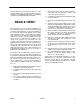
5. All personnel in the platform shall, at all times, wear approved fall protection devices and other safety gear as required. All procedures herein are based on the use of the machine under proper operating conditions, with no deviations from original design intent... as per OSHA regulations and applicable ANSI standards. 6. Load limits specified by the manufacturer shall not be exceeded. 7. Instruction and warning placards must be legible.
REVISON LOG September 15, 1985 October, 1996 February 15, 1999 August 20, 2007 f - Original Issue Revised Revised Revised – JLG Lift – 3120270
TABLE OF CONTENTS SECTION 1 - SAFETY PRECAUTIONS 1.1 1.2 1.3 1.4 1.5 1.6 1.7 General . . . . . . . . . . . . . . . . . . . . . . . . . . . . . . . . . . . . . . . . . . . . . . . . . . . . . . . . . . . . . . . . . . . . . .1-1 Driving/Towing. . . . . . . . . . . . . . . . . . . . . . . . . . . . . . . . . . . . . . . . . . . . . . . . . . . . . . . . . . . . . . . . .1-1 Electrocution Hazard. . . . . . . . . . . . . . . . . . . . . . . . . . . . . . . . . . . . . . . . . . . . . . . . . . . . . . . . . .
TABLE OF CONTENTS (Continued) SECTION 4 - MACHINE OPERATION 4.1 4.2 4.3 4.4 4.5 4.6 4.7 4.8 4.9 4.10 4.11 4.12 4.13 4.14 Description . . . . . . . . . . . . . . . . . . . . . . . . . . . . . . . . . . . . . . . . . . . . . . . . . . . . . . . . . . . . . . . . . . .4-1 General . . . . . . . . . . . . . . . . . . . . . . . . . . . . . . . . . . . . . . . . . . . . . . . . . . . . . . . . . . . . . . . . . . . . . .4-1 Engine Operation . . . . . . . . . . . . . . . . . . . . . . . . . . . . . . . . . .
TABLE OF CONTENTS SECTION 6 - EMERGENCY PROCEDURES 6.1 6.2 6.3 6.4 6.5 General . . . . . . . . . . . . . . . . . . . . . . . . . . . . . . . . . . . . . . . . . . . . . . . . . . . . . . . . . . . . . . . . . . . . . .6-1 Emergency Towing Procedures . . . . . . . . . . . . . . . . . . . . . . . . . . . . . . . . . . . . . . . . . . . . . . . . . . .6-1 Emergency Controls and Their Locations . . . . . . . . . . . . . . . . . . . . . . . . . . . . . . . . . . . . . . . . . . .
TABLE OF CONTENTS (Continued) LIST OF TABLES 1-1 2-1 7-1 iv Minimum Safe Approach Distances (M.S.A.D.) to energized (exposed or insulated) power lines and parts . . . . . . . . . . . . . . . . . . . . . . . . . . . . . . . . . . . . . . . . . . . . . . . . . . . . . . . . . .1-2 Lubrication Chart. . . . . . . . . . . . . . . . . . . . . . . . . . . . . . . . . . . . . . . . . . . . . . . . . . . . . . . . . . . . . . .2-13 Inspection and Repair Log . . . . . . . . . . . . . . . . . . . . . . . . . . . .
SECTION 1 - SAFETY PRECAUTIONS SECTION 1. SAFETY PRECAUTIONS 1.1 GENERAL 1.2 DRIVING/TOWING This section prescribes the proper and safe practices for major areas of machine usage. In order to promote proper usage of the machine, it is mandatory that a daily routine be established based on instructions given in this section. A maintenance program must be also be established by a qualified person and must be followed to ensure that the machine is safe to operate.
SECTION 1 - SAFETY PRECAUTIONS Table 1-1. Minimum Safe Approach Distances (M.S.A.D.) to energized (exposed or insulated) power lines and parts Voltage Range (Phase to Phase) MINIMUM SAFE APPROACH DISTANCE in Feet (Meters) 0 to 300V AVOID CONTACT Over 300V to 50 KV 10 (3) Over 50KV to 200 KV 15 (5) Over 200 KV to 350 KV 20 (6) Over 350 KV to 500 KV 25 (8) Over 500 KV to 750 KV 35 (11) Over 750 KV to 1000 KV 45 (14) DANGER: DO NOT maneuver machine or personnel inside PROHIBITED ZONE.
SECTION 1 - SAFETY PRECAUTIONS • AN OPERATOR MUST NOT ACCEPT OPERATING RESPONSIBILITIES UNTIL ADEQUATE TRAINING HAS BEEN GIVEN BY COMPETENT AND AUTHORIZED PERSONS. • BEFORE OPERATION, CHECK WORK AREA FOR OVERHEAD ELECTRIC LINES, MACHINE TRAFFIC SUCH AS BRIDGE CRANES, HIGHWAY, RAILWAY AND CONSTRUCTION EQUIPMENT. • NEVER DISABLE OR MODIFY THE FOOTSWITCH OR ANY OTHER SAFETY DEVICE. ANY UNAUTHORIZED MODIFICATION OF THE MACHINE IS A SAFETY VIOLATION AND IS A VIOLATION OF OSHA REGULATIONS AND ANSI STANDARDS.
SECTION 1 - SAFETY PRECAUTIONS • ALWAYS POSITION BOOM OVER REAR (DRIVE) AXLE IN LINE WITH DIRECTION OF TRAVEL. REMEMBER, IF BOOM IS OVER FRONT (STEER) AXLE, DIRECTION OF STEER AND DRIVE MOVEMENT WILL BE OPPOSITE FROM NORMAL OPERATION. . • READ AND OBEY ALL DANGERS, WARNINGS, CAUT I O N S A N D O P E R AT I N G I N S T R U C T I O N S O N MACHINE AND IN THIS MANUAL. • BE FAMILIAR WITH LOCATION AND OPERATION OF GROUND STATION CONTROLS. • DO NOT USE DRIVE FUNCTION TO POSITION PLATFORM CLOSE TO OBSTACLES.
SECTION 1 - SAFETY PRECAUTIONS 1.6 OPERATION. • READ YOUR MANUAL. UNDERSTAND WHAT YOU’VE READ - THEN BEGIN OPERATIONS. • CHECK TRAVEL PATH FOR PERSONS, HOLES, BUMPS, DROP-OFFS, OBSTRUCTIONS, DEBRIS, AND COVERINGS WHICH MAY CONCEAL HOLES AND OTHER HAZARDS. • TRAVEL IS PERMITTED ON GRADES AND SIDESLOPES NO GREATER THAN THOSE INDICATED IN WARNING PLACARD AT MACHINE PLATFORM. • OPERATION WITH BOOM RAISED IS RESTRICTED TO FIRM, LEVEL AND UNIFORM SURFACE.
SECTION 1 - SAFETY PRECAUTIONS • TRANSFERS BETWEEN A STRUCTURE AND THE AERIAL PLATFORM EXPOSE OPERATORS TO FALL HAZARDS. THIS PRACTICE SHOULD BE DISCOURAGED WHEREVER POSSIBLE. WHERE TRANSFER MUST BE ACCOMPLISHED TO PERFORM THE JOB TWO LANYARDS WITH AN APPROVED FALL PROTECTION DEVICE WILL BE USED. ONE LANYARD SHOULD BE ATTACHED TO THE AERIAL PLATFORM. THE OTHER TO THE STRUCTURE.
SECTION 1 - SAFETY PRECAUTIONS FERING WITH OPERATING CONTROLS AND PERSONS IN PLATFORM. . • ENSURE THAT OPERATORS OF OTHER OVERHEAD AND FLOOR MACHINES ARE AWARE OF THE AERIAL PLATFORMS PRESENCE. DISCONNECT POWER TO OVERHEAD CRANES. POSITION BARRICADES ON FLOOR IF NECESSARY. • NEVER "SLAM" A CONTROL SWITCH OR LEVER THROUGH NEUTRAL TO THE OPPOSITE DIRECTION. ALWAYS RETURN SWITCH TO NEUTRAL AND STOP; THEN MOVE SWITCH TO THE DESIRED POSITION. OPERATE LEVERS WITH SLOW, EVEN PRESSURE.
SECTION 1 - SAFETY PRECAUTIONS • NEVER ATTEMPT TO FREE A MACHINE STUCK IN SOFT GROUND OR ASSIST A MACHINE UP A STEEP HILL OR RAMP BY USING BOOM "LIFT", "TELESCOPE", OR "SWING" FUNCTIONS. • NEVER ATTACH WIRE, CABLE, OR ANY SIMILAR ITEMS TO PLATFORM. • DO NOT PLACE BOOM OR PLATFORM AGAINST ANY STRUCTURE TO STEADY PLATFORM OR SUPPORT STRUCTURES. • DO NOT USE THE LIFT, SWING, OR TELESCOPE FUNCTIONS FOR THE BOOM, TO MOVE EITHER THE MACHINE OR OTHER OBJECTS.
SECTION 2 - PREPARATION AND INSPECTION SECTION 2. PREPARATION AND INSPECTION 2.1 GENERAL 2.3 This section provides the necessary information needed by those personnel that are responsible to place the machine in operation readiness, and lists checks that are performed prior to use of the machine. It is important that the information contained in this section be read and understood before any attempt is made to operate the machine.
SECTION 2 - PREPARATION AND INSPECTION 9. Check extending axles for visible damage and loose or missing parts. 10. Check fuel tank for damage, leakage and filler cap for security. 10. Check oscillating axle (if equipped) for loose, missing and worn parts, pivot pin and lockout cylinder pins for security, lockout cylinders and hydraulic hoses for damage and leaks. 11. Check hydraulic reservoir and hydraulic lines for damage, leakage and security. Turntable 1.
SECTION 2 - PREPARATION AND INSPECTION Figure 2-1.
SECTION 2 - PREPARATION AND INSPECTION 11. Check horizontal and capacity limit switches mounted on turntable for security of mounting, damage to switch arms and rollers; and for debris. 12. Check boom tape for correct length and tearing or defacing at any point. Extend-A-Reach (If Equipped) 1. Check the slave cylinder, weld link and cross pins, and lines for visible damage, wear, lubrication, evidence of leakage, and security. 2.
SECTION 2 - PREPARATION AND INSPECTION 4. 4. Machine Log. Ensure a machine operating record or log is kept, check to see that it is current and that no entries have been left uncleared, leaving machine in an unsafe condition for operation. NOTE: Check boom horizontal limit switch for proper operation and security, both visually and manually. Switch must shut down high engine and high drive speed when boom is raised above horizontal: 6. Check platform footswitch for proper operation.
SECTION 2 - PREPARATION AND INSPECTION Figure 2-2.
SECTION 2 - PREPARATION AND INSPECTION GENERAL NOTE: Begin the “Walk-Around Inspection” at Item 1, as noted on the diagram. Continue to the right (counterclockwise viewed from top) checking each item in sequence for the conditions listed in the “WalkAround Inspection Checklist”. TO AVOID INJURY, DO NOT OPERATE A MACHINE UNTIL ALL MALFUNCTIONS HAVE BEEN CORRECTED. USE OF A MALFUNCTIONING MACHINE IS A SAFETY VIOLATION. TO AVOID POSSIBLE INJURY, BE SURE MACHINE POWER IS “OFF” DURING WALK-AROUND INSPECTION.
SECTION 2 - PREPARATION AND INSPECTION 20. Control Valves (Tank Compartment) - No loose or missing parts, no evidence of leakage, no damaged wires. 21. Hydraulic Oil Supply - Recommended oil level in sight gauge. (Check level with cold oil, systems shut down, machine in stowed position) Cap in place and secure. 22. Steer Cylinder Assembly - Properly secured, no visible damage or signs of leakage. 23.
SECTION 2 - PREPARATION AND INSPECTION 51. Drive Hub, Left Rear - No visible damage, no evidence of leakage. 52. Drive Motor and Brake, Left Rear - No visible damage, no evidence of leakage. 53. Spindle, Left Rear - Properly secured, no loose or missing parts, no visible damage. (4 Wheel Steer) 54. Tie Rod and Steering Linkage, Left Rear - No loose or missing parts, no visible damage. Tie rod end studs locked. (4 Wheel Steer) 55.
SECTION 2 - PREPARATION AND INSPECTION 2.5 Machines Without Jacks DAILY FUNCTIONAL CHECK a. Position the boom over the drive wheel end of machine. Position STEER/AXLES valve, located adjacent to the right front wheel, to AXLES. Remove axle lock pins. PROPER AXLE EXTENSION MUST BE CHECKED AND VERIFIED PRIOR TO ANY OTHER SYSTEMS AND/OR FUNCTIONS. A functional check of all systems should be performed, once the walk-around inspection is complete, in an area free of overhead and ground level obstructions.
SECTION 2 - PREPARATION AND INSPECTION control switch to down and hold until the wheels on the selected axle rise from the ground. e. Position the Jack/Steer/Axles select switch to AXLES. Then, position the Steer/Axles/Jack control switch to left until the axles are fully extended. On machines with fixed axles, install axle lock pins. If extending the steer axle, also install the tie rod lock pins and steer cylinder lock pin. f. Position the JACK control to the up position to lower the machine.
SECTION 2 - PREPARATION AND INSPECTION 14. Auxiliary Power. 2.7 Operate each function control switch (e.g. TELE, LIFT and SWING) to assure that they function in both directions using auxiliary power instead of engine power. 15. Ground Controls. Place GROUND/PLATFORM SELECT switch to GROUND. Start engine. Platform controls should not operate. 2.6 BATTERY MAINTENANCE TO AVOID INJURY FROM AN EXPLOSION, DO NOT SMOKE OR ALLOW SPARKS OR A FLAME NEAR BATTERY DURING SERVICING. Battery Maintenance 1.
SECTION 2 - PREPARATION AND INSPECTION Figure 2-6.
SECTION 2 - PREPARATION AND INSPECTION Table 2-1. Lubrication Chart Components Interval Number/Type Lube Points Capacity Lube Level/Fill Plug 2.75 pt.
SECTION 2 - PREPARATION AND INSPECTION Table 2-1. Lubrication Chart Components Interval Number/Type Lube Points Capacity Lube 3 Months 150 hrs Hours 6 Months 300 hrs 1 Year 600 hrs Comments 2 Years 1200 hrs 14 Boom Chain Retract Sheave 1 Grease Fitting A/R MPG X 15 Boom Pivot Bushings 2 Grease Fittings A/R MoS2 X 16 Engine Crankcase Fill Cap Refer to Engine Manual EO Check daily. Change in accordance wth engine manual.
SECTION 2 - PREPARATION AND INSPECTION Table 2-1.
Figure 2-7.
SECTION 2 - PREPARATION AND INSPECTION This page left blank intentionally.
SECTION 3 - USER RESPONSIBILITIES AND MACHINE CONTROL SECTION 3. USER RESPONSIBILITIES AND MACHINE CONTROL 3.1 avoidance of potential hazards in the work place; with particular attention to the work to be performed. GENERAL 4. Proper use of all required personnel safety equipment, in particular the wearing of a safety harness or other approved fall protection devices with a lanyard attached to the platform at all times.
SECTION 3 - USER RESPONSIBILITIES AND MACHINE CONTROL 3.3 OPERATING CHARACTERISTICS AND LIMITATIONS General A thorough knowledge of the operating characteristics and limitations of the machine is always the first requirement for any user, regardless of the user’s experience with similar types of equipment. Placards Machine stability is based on two positions which are called FORWARD STABILITY and BACKWARD STABILITY. The machines position of least forward stability is shown in Figure 3-1.
SECTION 3 - USER RESPONSIBILITIES AND MACHINE CONTROL Figure 3-1.
SECTION 3 - USER RESPONSIBILITIES AND MACHINE CONTROL Figure 3-2.
SECTION 3 - USER RESPONSIBILITIES AND MACHINE CONTROL 3.4 3. Ignition. CONTROLS AND INDICATORS The machine is equipped with an on-off ignition switch and a separate start push button switch on the ground control panel which supplies electrical power to the start solenoid when the ignition switch is placed in the ON position and the START button is depressed. Ground Controls PERFORM PRE-OPERATIONAL CHECKS AND INSPECTIONS FROM THE GROUND CONTROL STATION.
SECTION 3 - USER RESPONSIBILITIES AND MACHINE CONTROL Figure 3-3.
SECTION 3 - USER RESPONSIBILITIES AND MACHINE CONTROL Figure 3-4.
SECTION 3 - USER RESPONSIBILITIES AND MACHINE CONTROL Figure 3-5.
SECTION 3 - USER RESPONSIBILITIES AND MACHINE CONTROL Figure 3-6.
SECTION 3 - USER RESPONSIBILITIES AND MACHINE CONTROL Figure 3-7.
SECTION 3 - USER RESPONSIBILITIES AND MACHINE CONTROL are extended and the retaining pins are properly installed. 9. L.P. Gas/Gasoline Select Switch. An optional two position contact toggle switch supplies electrical power to open the gasoline shut-off solenoid and closes the LP gas shut-off solenoid when placed in the “GASOLINE” position. This switch supplies electrical power to open the LP gas shut-off solenoid and closes the gasoline shut-off solenoid when positioned to the LP position. 17.
SECTION 3 - USER RESPONSIBILITIES AND MACHINE CONTROL 2. Power/Emergency Stop. An on-off POWER/EMERGENCY STOP switch and a separate START push button on the platform console supply electrical power to the starter solenoid, when the power switch is pulled out to the “on” position and the START button is depressed. TO AVOID SERIOUS INJURY, DO NOT OPERATE MACHINE IF ANY CONTROL LEVERS OR TOGGLE SWITCHES CONTROLLING PLATFORM MOVEMENT DO NOT RETURN TO THE OFF POSITION WHEN RELEASED. 23. Rotate (If equipped).
SECTION 3 - USER RESPONSIBILITIES AND MACHINE CONTROL Figure 3-8.
SECTION 3 - USER RESPONSIBILITIES AND MACHINE CONTROL 7. Telescope. 11. Wheel Speed. The two position WHEEL SPEED control switch allows the operator to select high wheel motor speed when in the high position. When used in conjunction with high ENGINE SPEED, it gives the machine a faster drive speed. The MAIN TELESCOPE control switch or MAIN TELESCOPE control lever (hydraulic controls) provides extension and retraction or the boom when positioned to in or out. 8. Steer/Axles/Jack.
SECTION 3 - USER RESPONSIBILITIES AND MACHINE CONTROL 16. Platform Rotate (If Equipped). The platform ROTATE control switch allows operator to rotate the basket to the left or right when positioned to the desired direction. NOTE: The main function of the auxiliary power is to lower the platform in the event of primary power failure. Determine the reason for primary power failure and have the problem corrected by a qualified service technician. 17. Extend-A-Reach (If Equipped).
SECTION 3 - USER RESPONSIBILITIES AND MACHINE CONTROL 25. Lights Switch (If equipped). 3. Start Button. The LIGHTS switch allows the operator to turn the installed light options on or off. The START button is a momentary contact, pushbutton switch. With the POWER/EMERGENCY STOP switch pulled up and the START button depressed, electrical power is supplied to the start solenoid. 26. Capacity Indicator (If equipped). The CAPACITY INDICATOR GAUGE is mounted on the left side of the platform console.
SECTION 3 - USER RESPONSIBILITIES AND MACHINE CONTROL 1. 2. 3. 4. 5. 6. Footswitch Power/Emergency Stop Start Button Warning Horn Chassis Out of Level Warning Light Lift 7. 8. 9. 10. 11. 12. Telescope Steer/Axles/Jack Swing Engine Speed Wheel Speed Pump Volume 13. 14. 15. 16. 17. 18. Creep Drive Platform Level Platform Rotate Extend-A-Reach Choke 19. 20. 21. 22. 23. 24. Glow Plug Engine Distress Light Auxiliary Power Axles Set Indicator Lights Switch Capacity Indicator Figure 3-9.
SECTION 3 - USER RESPONSIBILITIES AND MACHINE CONTROL 8. Steer/Axles. On standard machines, positioning the STEER/ AXLES control switch right or left enables steering the machine to the right or the left. On machines equipped with hydraulic extendable axles, the function the switch controls is dependent upon the position of the lever on the STEER/AXLES SELECTOR valve. TO AVOID PERSONNEL INJURY OR MACHINE DAMAGE, USE SLOW FUNCTION SPEED CONTROL WHEN POSITIONING THE PLATFORM IN CLOSE QUARTERS. 12.
SECTION 3 - USER RESPONSIBILITIES AND MACHINE CONTROL 18. Choke (If Equipped). A push-button switch supplies power to the choke solenoid for cold weather starting. 19. Glow Plug (If Equipped). NOTE: Auxiliary power is primarily intended for platform lowering in the event of primary power failure.
SECTION 3 - USER RESPONSIBILITIES AND MACHINE CONTROL Platform Station - Prior to September 1991 (Standard Machines) NOTE: For engine starting, the footswitch must be in the released (up) position. Footswitch must be actuated in order for controls to function. 1. Footswitch. This feature makes it necessary to depress the footswitch to allow operation of the controls. TO AVOID SERIOUS INJURY, DO NOT REMOVE, MODIFY OR DISABLE THE FOOTSWITCH BY BLOCKING OR ANY OTHER MEANS.
SECTION 3 - USER RESPONSIBILITIES AND MACHINE CONTROL Figure 3-10. Control Console - Prior to Sept.
SECTION 3 - USER RESPONSIBILITIES AND MACHINE CONTROL NOTE: When the boom is above horizontal and if either the ENGINE SPEED, DRIVE SPEED, or WHEEL MOTOR SPEED are positioned to HIGH, high speed functions are automatically cut out and the machine continues to operate at a lower speed. 14. Platform Level. The PLATFORM LEVEL control switch allows the operator to compensate for any difference in the automatic self-leveling system by positioning the switch to UP or DOWN. 15. Platform Rotate (If Equipped).
SECTION 3 - USER RESPONSIBILITIES AND MACHINE CONTROL NOTE: The main function of the auxiliary power is to lower the platform in the event of primary power failure. Determine the reason for primary power failure and have the problem corrected by a qualified service technician. 22. Lights Switch (If equipped). The LIGHTS switch allows the operator to turn the installed light options (except beacon light) on or off. 23. Beacon Switch (If equipped).
SECTION 3 - USER RESPONSIBILITIES AND MACHINE CONTROL Figure 3-11. Control Console - Prior to Sept.
SECTION 3 - USER RESPONSIBILITIES AND MACHINE CONTROL 3. Start Button. The START button is a momentary contact, pushbutton switch. With the IGNITION/EMERGENCY STOP switch pulled up and the START button depressed, electrical power is supplied to the start solenoid. TO AVOID SERIOUS INJURY, DO NOT OPERATE THE MACHINE IF ANY CONTROL LEVERS OR TOGGLE SWITCHES CONTROLLING PLATFORM MOVEMENT DO NOT RETURN TO THE OFF OR NEUTRAL POSITION WHEN RELEASED. 6. Lift. 4. Warning Horn.
SECTION 3 - USER RESPONSIBILITIES AND MACHINE CONTROL 11. Wheel Drive/4 Wheel Drive. 18. Auxiliary Power. The two position 2 WHEEL DRIVE/4 WHEEL DRIVE control switch allows the operator to select high speed (2 WHEEL DRIVE) or low speed (4 WHEEL DRIVE). The AUXILIARY POWER control switch energizes the electrically operated hydraulic pump, when actuated. The switch must be held ON for duration of auxiliary pump use.
SECTION 3 - USER RESPONSIBILITIES AND MACHINE CONTROL 19. Lights Switch (If equipped). The LIGHTS switch allows the operator to turn the installed light options (except beacon light) on or off. TO AVOID SERIOUS INJURY, DO NOT REMOVE, MODIFY OR DISABLE THE FOOTSWITCH BY BLOCKING OR ANY OTHER MEANS. 20. Beacon Switch (If equipped). The BEACON switch allows the operator to turn the beacon light on or off. 21. Capacity Indicator (If equipped).
SECTION 3 - USER RESPONSIBILITIES AND MACHINE CONTROL Figure 3-12. Control Console - Prior to Sept.
SECTION 3 - USER RESPONSIBILITIES AND MACHINE CONTROL NOTE: LIFT, SWING, and DRIVE control levers or switches are spring-loaded and will automatically return to the neutral (OFF) position when released. TO AVOID SERIOUS INJURY, DO NOT OPERATE THE MACHINE IF ANY CONTROL LEVERS OR TOGGLE SWITCHES CONTROLLING PLATFORM MOVEMENT DO NOT RETURN TO THE OFF OR NEUTRAL POSITION WHEN RELEASED.
SECTION 3 - USER RESPONSIBILITIES AND MACHINE CONTROL 15. Platform Level. The PLATFORM LEVEL control switch allows the operator to compensate for any difference in the automatic self-leveling system by positioning the switch to UP or DOWN. NOTE: Auxiliary power is primarily intended for platform lowering in the event of primary power failure. However, auxiliary power may be used for platform positioning when operating in close quarters in the following sequence: a. Position PLATFORM/GROUND PLATFORM. 16.
SECTION 3 - USER RESPONSIBILITIES AND MACHINE CONTROL 24. Capacity Indicator (If equipped). 4. Warning Horn. A push-type HORN switch, when pressed, supplies electrical power to activate the horn. The CAPACITY INDICATOR GAUGE is mounted on the left side of the platform console box. The indicator scale is visible through a lens and indicates the maximum platform load allowable at any given boom angle and extension based on the color stripe visible at the point where the fly boom enters the mid boom. 5.
SECTION 3 - USER RESPONSIBILITIES AND MACHINE CONTROL Figure 3-13. Control Console - Prior to Sept.
SECTION 3 - USER RESPONSIBILITIES AND MACHINE CONTROL 8. Steer/Axles. 12. Pump Volume. The two-position PUMP VOLUME control switch allows the operator to select high pump flow, providing additional speed to all functions when positioned to HIGH. When used in conjunction with high ENGINE SPEED and WHEEL MOTOR SPEED switches, it gives the machine a faster drive speed range.
SECTION 3 - USER RESPONSIBILITIES AND MACHINE CONTROL 20. Axles Not Set Indicator (If equipped). a. Position PLATFORM/GROUND switch to PLATFORM. The red axles not set indicator lights to inform the operator that the axles are not set and locked (pinned) in position. b. Position the IGNITION/EMERGENCY STOP switch to ON. c. Depress and hold the footswitch. 21. 2 Wheel Drive/4 Wheel Drive. d. Operate appropriate control switch or lever for desired function and hold.
SECTION 3 - USER RESPONSIBILITIES AND MACHINE CONTROL Figure 3-14.
SECTION 3 - USER RESPONSIBILITIES AND MACHINE CONTROL 2. Ignition/Emergency Stop. 7. Telescope. The TELESCOPE control switch provides extension and retraction or the boom when positioned to IN or OUT. An ON-OFF IGNITION/EMERGENCY STOP switch and a separate START push button on the platform console supply electrical power to the starter solenoid, when the ignition switch is pulled out to the “IGNITION ON” position and the START button is depressed. 8. Steer/Axles.
SECTION 3 - USER RESPONSIBILITIES AND MACHINE CONTROL 19. Glo-Plug (If Equipped). This push-button switch when depressed supplies power to the diesel engine glow plugs for cold weather start. See diesel engine operator manual for instructions. TO AVOID PERSONNEL INJURY OR MACHINE DAMAGE, USE SLOW FUNCTION SPEED CONTROL WHEN POSITIONING THE PLATFORM IN CLOSE QUARTERS. 12. Pump Volume. 20. Auxiliary Power.
SECTION 3 - USER RESPONSIBILITIES AND MACHINE CONTROL e. Position AUXILIARY POWER switch to ON and hold. f. Release AUXILIARY POWER switch, selected control switch or lever, and footswitch. TO AVOID SERIOUS INJURY, DO NOT REMOVE, MODIFY OR DISABLE THE FOOTSWITCH BY BLOCKING OR ANY OTHER MEANS. g. Position IGNITION/EMERGENCY STOP switch to OFF. 21. Lights Switch (If equipped). The LIGHTS switch allows the operator to turn the installed light options (except beacon light) on or off.
SECTION 3 - USER RESPONSIBILITIES AND MACHINE CONTROL Figure 3-15.
SECTION 3 - USER RESPONSIBILITIES AND MACHINE CONTROL Figure 3-16.
SECTION 3 - USER RESPONSIBILITIES AND MACHINE CONTROL NOTE: LIFT, SWING, and DRIVE control levers or switches are spring-loaded and will automatically return to the neutral (OFF) position when released. 10. Engine Speed. TO AVOID SERIOUS INJURY, DO NOT OPERATE THE MACHINE IF ANY CONTROL LEVERS OR TOGGLE SWITCHES CONTROLLING PLATFORM MOVEMENT DO NOT RETURN TO THE OFF OR NEUTRAL POSITION WHEN RELEASED. 11. Wheel Speed.
SECTION 3 - USER RESPONSIBILITIES AND MACHINE CONTROL 17. Glo-Plug (If Equipped). d. Operate appropriate control switch or lever for desired function and hold. This push-button switch when depressed supplies power to the diesel engine glow plugs for cold weather start. See diesel engine operator manual for instructions. e. Position AUXILIARY POWER switch to ON and hold. f. Release AUXILIARY POWER switch, selected control switch or lever, and footswitch. 18. Auxiliary Power. g.
SECTION 3 - USER RESPONSIBILITIES AND MACHINE CONTROL Figure 3-17.
SECTION 3 - USER RESPONSIBILITIES AND MACHINE CONTROL Figure 3-18.
SECTION 3 - USER RESPONSIBILITIES AND MACHINE CONTROL Figure 3-19.
SECTION 3 - USER RESPONSIBILITIES AND MACHINE CONTROL Figure 3-20.
SECTION 4 - MACHINE OPERATION SECTION 4. MACHINE OPERATION 4.1 DESCRIPTION This machine is a self-propelled aerial work platform on the end of an elevating, telescoping and rotating boom. The JLG Lift’s intended purpose is to position personnel with their tools and supplies at positions above ground level. The machine can be used to reach work areas located above and over machinery or equipment. The JLG Lift has a primary operator Control Station in the platform.
SECTION 4 - MACHINE OPERATION 4.3 Shutdown Procedure ENGINE OPERATION NOTE: Initial starting should always be performed from the Ground Control station. Starting Procedure IF AN ENGINE MALFUNCTION NECESSITATES UNSCHEDULED SHUTDOWN, DETERMINE AND CORRECT CAUSE BEFORE RESUMING ANY OPERATION. 1. Check engine oil. If necessary, add oil in accor- 1. Remove all load and allow engine to operate at dance with the Engine Manufacturer’s manual.
SECTION 4 - MACHINE OPERATION BEFORE DRIVING, MAKE SURE BOOM IS POSITIONED OVER REAR AXLE. IF BOOM IS OVER FRONT AXLE (STEER WHEELS), STEER AND DRIVE CONTROLS WILL MOVE IN OPPOSITE DIRECTIONS TO MACHINE CONTROLS. NOTE: For smoother operation when driving with fully extended boom, place DRIVE control to SLOW before stopping. 4.5 STEERING Depress footswitch to steer machine, push on the left side of the switch to steer left, on the right side to steer right. Traveling Forward or Reverse 1.
SECTION 4 - MACHINE OPERATION Figure 4-1. Grade and Side Slope Loading From Positions Above Ground Level Platform Level Adjustment 1. Leveling UP. Depress footswitch to raise plat- Before loading weight to platform above ground level: 1. Determine what the total rated capacity weight form, position PLATFORM LEVEL control switch UP and hold until platform is level. will be after additional weight is loaded (personnel, tools and supplies). 2. Leveling DOWN.
SECTION 4 - MACHINE OPERATION 4.8 Swinging the Boom BOOM A RED TILT ALARM WARNING LIGHT, LOCATED ON THE CONTROL CONSOLE, LIGHTS WHEN THE CHASSIS IS ON A SEVERE SLOPE (5 DEGREES OR GREATER). DO NOT SWING, EXTEND OR RAISE BOOM ABOVE HORIZONTAL WHEN LIT. DO NOT DEPEND ON TILT ALARM AS A LEVEL INDICATOR FOR THE CHASSIS. TILT ALARM INDICATES CHASSIS IS ON A SEVERE SLOPE (5 DEGREES OR GREATER). CHASSIS MUST BE LEVEL BEFORE SWINGING, EXTENDING OR RAISING BOOM ABOVE HORIZONTAL.
SECTION 4 - MACHINE OPERATION 4. Position LIFT control to DOWN and hold until 4.10 TIE DOWN AND LIFTING drive wheels rise from the ground; it may be necessary to feather the lift control to maintain drive wheel elevation. When transporting machine, boom must be in the stowed mode with turntable lock pin engaged and machine securely tied down to truck or trailer deck. Four tie down eyes are provided in the frame slab, one at each corner of the machine. 5.
Figure 4-2.
SECTION 4 - MACHINE OPERATION 13. To retract extendable axles: k. On machines with fixed axles, cycle the steer system in both directions to ensure the tie rods are properly locked. a. Position STEER/AXLES valve located adjacent to right front wheel to AXLES. b. Activate the machine hydraulic system and raise the boom and extend the boom no more than eight (8) feet. c.
SECTION 4 - MACHINE OPERATION 4. Place DRIVE control lever to FORWARD position and carefully drive machine up ascension ramp until left front wheel is on top of block. 10. You are now ready to operate all machine functions. 11. To retract extendable axles: a. Position STEER/AXLES valve located adjacent to right front wheel to AXLES. 5. Carefully activate SWING control lever and position boom over right side of machine. b.
SECTION 4 - MACHINE OPERATION 4.13 STEER/TOW SELECTOR (IF EQUIPPED) After towing the machine, complete the following: DO NOT ATTEMPT TO TOW MACHINE UNLESS EQUIPPED WITH COMPLETE TOW PACKAGE FROM MANUFACTURER. A push-pull type selector valve located adjacent to the steer cylinder assembly and linkage regulates oil flow in the steer circuit for steering and towing applications. When steering the unit (self-propelled operation) the valve knob is pushed IN.
SECTION 5 - OPTIONAL EQUIPMENT SECTION 5. OPTIONAL EQUIPMENT 5.1 Changing From LP Gas to Gasoline. ROTATOR 1. With engine operating on LP under a no-load condition, position DUAL FUEL switch at Ground Control Station to GASOLINE position. A Platform rotator allows for platform rotation 90 degrees from center in either direction. The rotator is designed to give added jobsite versatility. The platform should be returned to the center position for all other operations. 5.2 2.
SECTION 5 - OPTIONAL EQUIPMENT 5.6 TRAVEL ALARM 5.12 BOOM WIPERS A 12-volt alarm horn, mounted on the turntable, provides an audible warning when the machine is in the travel (DRIVE) mode. It will function in FORWARD or REVERSE to warn jobsite personnel the machine is traveling. 5.7 TILT ALARM Senses when the machine is out of level in any direction approximately 3 degrees and illuminates a warning light at the platform control station and sounds the machine’s horn, signaling the operator.
SECTION 6 - EMERGENCY PROCEDURES SECTION 6. EMERGENCY PROCEDURES 6.1 This section provides information on the procedures to be followed and on the systems and controls to be used in the event an emergency situation is encountered during machine operation. Prior to operation of the machine and periodically thereafter, the entire operating manual, including this section, should be reviewed by all personnel whose responsibilities include any work or contact with the machine. 6.2 2.
SECTION 6 - EMERGENCY PROCEDURES 3. Operate appropriate control switch or controller for desired function and hold. 6.4 EMERGENCY OPERATION 4. Position AUXILIARY POWER switch to ON and hold. Use of Ground Controls 5. Release AUXILIARY POWER switch, and appropriate control switch or controller. KNOW HOW TO USE THE GROUND CONTROLS IN AN EMERGENCY SITUATION. 6. Position POWER/EMERGENCY STOP switch to OFF.
SECTION 6 - EMERGENCY PROCEDURES Operator Unable to Control Machine 6.5 IF THE PLATFORM OPERATOR IS PINNED, TRAPPED OR UNABLE TO OPERATE OR CONTROL THE MACHINE: DO NOT OPERATE WITH PRIMARY POWER SOURCE (ENGINE OR ELECTRIC MOTOR) IF PERSONS ARE PINNED OR TRAPPED. USE AUXILIARY POWER INSTEAD. 1. Operate the machine from ground controls ONLY with the assistance of other personnel and equipment (cranes, overhead hoists, etc.) as may be be required to safely remove the danger or emergency condition.
SECTION 6 - EMERGENCY PROCEDURES This page left blank intentionally.
SECTION 7 - INSPECTION AND REPAIR LOG SECTION 7. INSPECTION AND REPAIR LOG Table 7-1.
SECTION 7 - INSPECTION AND REPAIR LOG Table 7-1.
Corporate Office JLG Industries, Inc. 1 JLG Drive McConnellsburg PA. 17233-9533 USA Phone: (717) 485-5161 Fax: (717) 485-6417 JLG Worldwide Locations JLG Industries (Australia) P.O. Box 5119 11 Bolwarra Road Port Macquarie N.S.W. 2444 Australia Phone: (61) 2 65 811111 Fax: (61) 2 65 810122 JLG Latino Americana Ltda. Rua Eng.