Operation & Safety Manual Original Instructions Keep this manual with machine at all times.
CALIFORNIA PROPOSITION 65 BATTERY WARNING Battery posts, terminals and related accessories contain lead and lead compounds, chemical known to the State of California to cause cancer and reproductive harm. WASH HANDS AFTER HANDLING! CALIFORNIA PROPOSITION 65 EXHAUST WARNING Diesel Engine exhaust and some of its constituents are known to the State of California to cause cancer, birth defects and other reproductive harm.
Revision Log Revision Log REVISION LOG December 5, 2008 - A - Original Issue of Manual December 19, 2008 - B - Revised page 3-15. January 5, 2010 - C - Revised covers and pages b, 1-5, 1-6, 2-1, 2-6, 4-5, 4-8, 5-2, 5-14, 5-15, 5-16, 5-18, 5-20, 5-22, 5-24 thru 5-28, 5-30, 5-32, 7-3, 7-5, 7-16, 7-19, 7-21, 9-2 & 9-3.
Read This First Read This First This manual is a very important tool! Keep it with the machine at all times. The purpose of this manual is to provide owners, users, operators, lessors, and lessees with the precautions and operating procedures essential for the safe and proper machine operation for its intended purpose. Due to continuous product improvements, JLG Industries, Inc. reserves the right to make specification changes without prior notification. Contact JLG Industries, Inc.
Read This First This product must comply with all safety related bulletins. Contact JLG Industries, Inc. or the local authorized JLG representative for information regarding safetyrelated bulletins which may have been issued for this product. JLG Industries, Inc. sends safety related bulletins to the owner of record of this machine. Contact JLG Industries, Inc. to ensure that the current owner records are updated and accurate. JLG Industries, Inc.
Read This First Other Publications Available Service Manual..........................................................................................31200452 Parts Manual .............................................................................................31200454 Note: The following standards may be referenced in this manual: ANSI is compliant to ANSI/ITSDF B56.6 AUS is compliant to AS 1418.
Table of Contents Table of Contents TABLE OF CONTENTS Revision Log Read This First Operator Qualifications ...................................................... b Modifications ...................................................................... b Other Publications Available .............................................. d Table of Contents Section 1 - General Safety Practices 1.1 Hazard Classification system...............................................
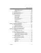
Table of Contents Boom Joystick .............................................................. 3-10 Frame Level Joystick.................................................... 3-12 Auxiliary Hydraulic Joystick .......................................... 3-13 Outrigger Joysticks ....................................................... 3-14 Right Panel ................................................................... 3-15 Accessory Control Lever (if equipped) .........................
Table of Contents 5.5 Use of the Capacity Chart....................................................5-4 Capacity Indicator Locations...........................................5-4 Sample Capacity Chart ...................................................5-6 Example ..........................................................................5-8 5.6 Attachment Installation ......................................................5-10 5.7 Hydraulic Operated Attachment.........................................5-12 5.
Table of Contents Transmission Oil........................................................... 7-17 Hydraulic Return Filter.................................................. 7-18 Engine Cooling System ................................................ 7-19 Battery .......................................................................... 7-20 Windshield Washer System (if equipped)..................... 7-21 Section 8 - Additional Checks Section 9 - Specifications 9.1 Product Specifications.....................
Section 1 - General Safety Practices SECTION 1 - GENERAL SAFETY PRACTICES 1.1 HAZARD CLASSIFICATION SYSTEM Safety Alert System and Safety Signal Words DANGER OW0010 DANGER indicates an imminently hazardous situation which, if not avoided, will result in death or serious injury. WARNING OW0021 WARNING indicates a potentially hazardous situation which, if not avoided, could result in death or serious injury.
Section 1 - General Safety Practices 1.3 OPERATION SAFETY Electrical Hazards 10 FT (3 M) OW0040 • This machine is not insulated and does not provide protection from contact or being near electrical current. • NEVER operate the telehandler in an area where overhead power lines, overhead or underground cables, or other power sources may exist without ensuring the appropriate power or utility company de-energizes the lines. • Always check for power lines before raising the boom.
Section 1 - General Safety Practices Tip Over Hazard General • For additional load requirements, refer to the appropriate capacity chart. OW0050 • Never use an attachment without the appropriate JLG approved capacity chart installed on the telehandler. • Understand how to properly use the capacity charts located in cab. • DO NOT exceed rated lift capacity. • Be sure that the ground conditions are able to support the machine.
Section 1 - General Safety Practices OH2291 • MAINTAIN proper tire pressure at all times. If proper tire pressures are not maintained, this machine could tip over. • Refer to manufacturer’s specifications for proper fill ratio and pressure requirements for tires equipped with ballast. OH20911 • Always wear the seat belt. • Keep head, arms, hands, legs and all other body parts inside operator’s cab at all times.
Section 1 - General Safety Practices Non-Suspended Load OW0060 • DO NOT drive with boom raised. Suspended Load OW0150 • Tether suspended loads to restrict movement. • Weight of all rigging (slings, etc.) must be included as part of load. • Beware of wind. Wind can cause a suspended load to swing and cause dangerous side loads - even with tag lines. • DO NOT attempt to use telehandler frame-leveling to compensate for load swing. • Keep heavy part of load closest to attachment.
Section 1 - General Safety Practices Travel Hazard 2-Wheel Front Steer 4-Wheel Circle Steer 4-Wheel Crab Steer OAL2030 • Steering characteristics differ between steer modes. Identify the steer mode settings of the telehandler being operated. • DO NOT change steer modes while traveling. Steer modes must be changed while telehandler is stationary. • Visually verify proper wheel alignment after each steer mode change.
Section 1 - General Safety Practices Load Falling Hazard OW0130 • Never suspend load from forks or other parts of carriage. • DO NOT burn or drill holes in fork(s). • Forks must be centered under load and spaced apart as far as possible.
Section 1 - General Safety Practices Lifting Personnel OW0170 • When lifting personnel, USE ONLY a JLG approved personnel work platform, with proper capacity chart displayed in the cab. OW0190 • DO NOT drive machine from cab when personnel are in platform.
Section 1 - General Safety Practices Driving Hazards On Slopes OW0200 To maintain sufficient traction and braking capabilities, travel on slopes as follows: • When unloaded, the rear of the machine is the “heavy end.” Drive with forks pointed downhill. • When loaded, the front of the machine is the “heavy end.” Drive with the forks pointed uphill. • For additional travel requirements, refer to the appropriate capacity chart.
Section 1 - General Safety Practices Pinch Points and Crush Hazards Stay clear of pinch points and rotating parts on the telehandler. OW0210 • Stay clear of moving parts while engine is running. OW0220 • Keep clear of steering tires and frame or other objects. OW0230 • Keep clear from under boom.
Section 1 - General Safety Practices OW0240 • Keep clear of boom holes. OW0250 • Keep arms and hands clear of attachment tilt cylinder. OW0260 • Keep hands and fingers clear of carriage and forks. OW0960 • Keep others away while operating.
Section 1 - General Safety Practices Fall Hazard OW0280 • Enter using the proper hand holds and steps provided. Always maintain 3-point contact when mounting or dismounting. Never grab control levers or steering wheel when mounting or dismounting the machine. • DO NOT get off the machine until the shutdown procedure on page 4-3 has been performed. OW0290 • DO NOT carry riders. Riders could fall off machine causing death or serious injury.
Section 1 - General Safety Practices Chemical Hazards Exhaust Fumes • DO NOT operate machine in an enclosed area without proper ventilation. • DO NOT operate the machine in hazardous environments unless approved for that purpose by JLG and site owner. Sparks from the electrical system and the engine exhaust can cause an explosion. • If spark arrestors are required, ensure they are in place and in good working order.
Section 1 - General Safety Practices This Page Intentionally Left Blank 1-14 3128447
Section 2 - Pre-Operation and Inspection SECTION 2 - PRE-OPERATION AND INSPECTION 2.1 PRE-OPERATION CHECK AND INSPECTION Note: Complete all required maintenance before operating unit. WARNING FALL HAZARD. Use extreme caution when checking items beyond your normal reach. Use an approved ladder. The pre-operation check & inspection, performed at beginning of each work shift or at each change of operator, should include the following: 1.
Section 2 - Pre-Operation and Inspection 8. Operational Check - Once the walk-around inspection is complete, perform a warm-up and operational check (see page 2-8) of all systems in an area free of overhead and ground level obstructions. See Section 3 - Controls and Indicators for more specific operating instructions. WARNING If telehandler does not operate properly, immediately bring machine to a stop, lower boom and attachment to ground and stop the engine.
Section 2 - Pre-Operation and Inspection 2.2 SAFETY DECALS Ensure all DANGER, WARNING, CAUTION and instructional decals and proper capacity charts are legible and in place. Clean and replace as required. 1705881 91503109 91503108 M O V I N G PA R T S c o u l d crush causing death o r s e r i o u s i n j u r y. Keep clear of wheels and moving parts while engine is running. ENGINE EXPLOSION could result in death or serious injury. N O R I D E R S .
Section 2 - Pre-Operation and Inspection CAPACITY CHARTS 91163028 91413061 VIEW OF CAB DASH 91503097 91563227 LUBRICATION AND MAINTENANCE MATERIAL HANDLER M O V I N G PA R T S c a n cut or entangle. Keep clear while engine is running.
Section 2 - Pre-Operation and Inspection 91513210 50 60 70 80 4105262 40 20 -10 0 10 30 M O V I N G PA R T S c o u l d c u t o r c r u s h c a u s i n g d e a t h o r s e r i o u s i n j u r y. K e e p c l e a r o f moving parts while engine is running. 9151-3210 REV - A A 91513210 M O V I N G PA R T S c o u l d crush causing death o r s e r i o u s i n j u r y. Keep clear of swing attachments and moving parts while engine is running.
Section 2 - Pre-Operation and Inspection 2.3 WALK-AROUND INSPECTION 1 18 17 2 16 3 15 4 5 5 14 6 13 7 12 8 9 10 11 OY1940 Begin your walk-around inspection at item 1, as noted below. Continue to your right (counterclockwise when viewed from top) checking each item in sequence. INSPECTION NOTE: On all components, make sure there are no loose or missing parts, that they are securely fastened and no visible leaks or excessive wear exists in addition to any other criteria mentioned.
Section 2 - Pre-Operation and Inspection 4. Wheel/Tire Assembly - Properly inflated and secured; no loose or missing lug nuts. Inspect for worn tread, cuts, tears or other discrepancies. 5. Mirrors - Clean and undamaged. 6. Cab and Electrical • General appearance; no visible damage. • Frame level indicator and window glass undamaged and clean. • Gauges, switches, joysticks, foot controls and horn operational. • Emergency escape hammer in place (enclosed cab only).
Section 2 - Pre-Operation and Inspection 2.4 WARM-UP AND OPERATIONAL CHECKS Warm-Up Check During warm-up period, check: 1. Heater, defroster and windshield wiper (if equipped). 2. Check all lighting systems (if equipped) for proper operation. 3. Adjust mirror(s) for maximum visibility. WARNING CUT/CRUSH/BURN HAZARD. Keep engine cover closed while engine is running except when checking transmission oil level and hydraulic filter condition indicator.
Section 2 - Pre-Operation and Inspection 2.5 OPERATOR CAB The telehandler is equipped with an open or enclosed ROPS/FOPS cab. WARNING Never operate telehandler unless the overhead guard and cab structure are in good condition. Any modification to this machine must be approved by JLG to assure compliance with ROPS/FOPS certification for this cab/machine configuration. If damaged, the CAB CANNOT BE REPAIRED. It must be REPLACED.
Section 2 - Pre-Operation and Inspection 2.6 WINDOWS Keep all windows and mirrors clean and unobstructed. Cab Door Window (if equipped) 3 4 2 1 OAL0011 • Cab door (1) must be closed during operation. • During operation the cab door window (2) must either be latched open or closed. • Open the cab door window and secure it in the latch (3). • Press latch release button inside the cab or pull on lever (4) outside the cab to unlatch the window.
Section 3 - Controls and Indicators SECTION 3 - CONTROLS AND INDICATORS 3.1 GENERAL This section provides the necessary information needed to understand control functions. Note: The manufacturer has no direct control over machine application and operation. The user and operator are responsible for conforming with good safety practices.
Section 3 - Controls and Indicators 3.2 CONTROLS 5 6 4 7 8 3 9 10 2 1 11 14 13 12 OY1282 1. Heater and Air Conditioning Controls (if equipped): See page 3-17. 2. Transmission Control Lever: See page 3-8. 3. Instrument Panel: See page 3-4. 4. Steering Wheel: Turning the steering wheel to the left or right steers the machine in the corresponding direction. Three steering modes are available. See “Steer Modes” on page 3-18. 5.
Section 3 - Controls and Indicators 11. Outrigger Joysticks: See page 3-14. 12. Accelerator Pedal: Pressing down the pedal increases engine and hydraulic speed. 13. Service Brake Pedal: The further the pedal is depressed, the slower the travel speed. 14. Ignition Switch: Key activated. See page 3-6.
Section 3 - Controls and Indicators Instrument Panel 9 8 1 OY1291 765 2 3 4 1. 3-in-1 Gauge and Display: a. Engine Coolant Temperature Gauge b. Engine Oil Pressure Gauge c. Fuel Gauge d. Display - See page 3-5. 2. Warning and Check Engine Indicators: Any combination of illumination indicates an engine fault and/or parameter that is outside of acceptable range. Engine may derate or shutdown. 3.
Section 3 - Controls and Indicators Display DISPLAY SHOWN WITH ENGINE FAULT ACTIVE 10 XXXXXX.X 11 12 XX.X V RPM XXXX 13 XXX.XX DISPLAY SHOWN WITH MACHINE FAULT ACTIVE 10 XXXXXX.X 11 XX.X V 12 RPM XXXX XXXX 14 OY1930 10. Operating Hours: Displays total hours of telehandler operation. 11. Voltmeter: Displays alternator output and battery condition. 12. Engine Speed: Displays engine speed in revolutions per minute (rpm). 13.
Section 3 - Controls and Indicators Ignition 0 I II III OY1470 • Position 0 - Engine off. • Position I - Voltage available for all electrical functions. • Position II - Engine preheat at temperatures below 0° C (32° F). Hold in position for approximately 10 seconds. • Position III - Engine start. In the event engine does not start, rotate key to position 0 then back to position III to re-engage the starter.
Section 3 - Controls and Indicators Park Brake OY1480 1 2 Park brake switch controls the application and release of the park brake. Indicator light on switch illuminates to indicate brake is applied. • Depress top of switch (1) to engage park brake. With park brake applied, transmission will not engage forward or reverse. • Depress bottom of switch (2) to disengage park brake. WARNING MACHINE ROLL-AWAY HAZARD.
Section 3 - Controls and Indicators Transmission Control Lever Direction of Travel Selection F N R 1 OAL0481 Transmission control lever (1) engages forward or reverse travel. • Lift and push lever forward for forward travel; lift and pull lever rearward for reverse travel. Move lever to centered position for neutral. • Forward or reverse travel can be selected while in any gear. • When traveling in reverse, the back-up alarm will automatically sound.
Section 3 - Controls and Indicators Gear Selection 1st 2nd 3rd 4th OAL0491 2 Gear selection is located on the twist grip handle (2) of transmission control lever. • Twist hand grip to select gear. • Select the appropriate gear for the task being performed. Use a lower gear when transporting a load. Use a higher gear only when driving unloaded for longer distances. • Slow down prior to downshifting. Do not downshift more than one gear at a time.
Section 3 - Controls and Indicators Boom Joystick 1 2 3 OY1310 The boom joystick (1) controls boom mode and boom and attachment functions. Boom Mode Boom mode is controlled by the left button (2). • Depress button to switch between standard and AccuPlace modes. Boom Functions - Standard Mode OY1960 With machine in standard mode, the joystick functions as a conventional telehandler.
Section 3 - Controls and Indicators Boom Functions - AccuPlace Mode OY1950 With machine in AccuPlace mode, a single motion of the joystick will move the attachment along a vertical or horizontal path. • Move the joystick back to lift vertically; move the joystick forward to lower vertically; move the joystick right to extend horizontally; move the joystick left to retract horizontally. • The speed of boom functions depends upon the amount of joystick travel in the corresponding direction.
Section 3 - Controls and Indicators Frame Level Joystick 1 OY1320 The frame level joystick (1) controls the left to right frame level. • Move the joystick left to rotate frame left; move the joystick right to rotate frame right. • A level indicator is located above the front cab window to permit the operator to determine whether the telehandler frame is level. WARNING TIP OVER HAZARD. Always move boom as low as possible while allowing for best visibility of right hand mirror before leveling frame.
Section 3 - Controls and Indicators Auxiliary Hydraulic Joystick 2 OY1330 The auxiliary hydraulic joystick (2) controls function of attachments that require hydraulic supply for operation. See Section 5 - Attachments for approved attachments and control instructions.
Section 3 - Controls and Indicators Outrigger Joysticks 1 OY1340 The outrigger joysticks (1) control the outriggers. • The left joystick controls the left outrigger and the right joystick controls the right outrigger. • Push joysticks forward to lower outriggers; push joysticks back to raise outriggers. • Use outriggers to increase stability and/or load capacity and in leveling the telehandler. Study capacity charts to determine maximum load capacities, with and without outriggers.
Section 3 - Controls and Indicators Right Panel 2 7 OY1301 6 3 4 5 2. Boom Ride Control Switch: Depress switch to activate boom ride control. Blue indicator light on switch flashes and slight boom movement may occur as system engages. Indicator then illuminates to indicate boom ride control is active. While activated and traveling, the system acts to cushion boom movement. Depress switch again to deactivate boom ride control.
Section 3 - Controls and Indicators Accessory Control Lever (if equipped) The accessory control lever (1) operates the turn signals, parking lights and headlights. 2 5 7 1 4 3 6 OY1350 Turn Signals • Push the lever forward (2) to activate the left turn signal. • Pull the lever back (3) to activate the right turn signal. • The lever must be manually returned to the center position to deactivate either turn signal. The lever will not cancel automatically after a turn.
Section 3 - Controls and Indicators Heater and Air Conditioning Controls (if equipped) 6 4 5 4 5 3 2 1 OY1361 1. Fan Speed Switch: Four position rotary switch. 2. Air Conditioning Switch: On/Off switch. 3. Temperature Control Switch: Adjustable rotary switch. 4. Air Vent: Two individually adjustable air vents. 5. Air Louver: Three individually adjustable air louvers. Third air louver located under operator seat. 6. Defroster Fan: Two speed fan.
Section 3 - Controls and Indicators 3.3 STEER MODES Three steer modes are available for operator use. 2-Wheel Front Steer 4-Wheel Circle Steer 4-Wheel Crab Steer OAL2030 Note: 2-Wheel Front Steer mode is required for travel on public roads. Steer Mode Change 1 2 3 OY1490 1. Bring machine to a stop using service brake while either circle steer mode (1) or crab steer mode (3) is selected. 4 5 OAM2400 2.
Section 3 - Controls and Indicators 3.4 OPERATOR SEAT Adjustments Prior to starting engine adjust seat for position and comfort. 3 4 1 2 OW0480 1. Suspension: Use knob to adjust suspension to the appropriate setting. Turn clockwise to increase stiffness. Turn counterclockwise to reduce stiffness. 2. Fore/Aft: Pull up on handle to move seat fore and aft. 3. Arm Rest: Arm rest can be moved up or down for comfort. 4. Seat Belt: Always fasten seat belt during operation.
Section 3 - Controls and Indicators Seat Belt OH20912 Fasten seat belt as follows: 1. Grasp both free ends of the belt making certain that belt webbing is not twisted or entangled. 2. With back straight in the seat, couple the retractable end (male end) of the belt into the receptacle (buckle) end of the belt. 3. With belt buckle positioned as low on the body as possible, pull the retractable end of the belt away from the buckle until it is tight across the lap. 4.
Section 3 - Controls and Indicators 3.5 BOOM ANGLE AND EXTENSION INDICATORS 1 50 60 70 80 2 40 20 -10 10 30 OW1220 • The boom angle indicator (1) is located on the left side of the boom. Use this indicator to determine the boom angle when using the capacity chart (see “Use of the Capacity Chart” on page 5-4). • The boom extension indicators (2) are located on the left side of the boom.
Section 3 - Controls and Indicators This Page Intentionally Left Blank 3-22 3128447
Section 4 - Operation SECTION 4 - OPERATION 4.1 ENGINE Starting the Engine This machine can be operated under normal conditions in temperatures of 0°F to 104°F (-20°C to 40°C). Consult JLG for operation outside this range or under abnormal conditions. 1. Make sure all controls are in “Neutral” and all electrical components (lights, heater, defroster, etc.) are turned off. Apply park brake. 2.
Section 4 - Operation Battery Boosted Starting OW0530 If battery-boost starting (jump-start) is necessary, proceed as follows: • Never allow vehicles to touch. • Connect the positive (+) jumper cable to positive (+) post of discharged battery. • Connect the opposite end of positive (+) jumper cable to positive (+) post of booster battery. • Connect the negative (-) jumper cable to negative (-) post on booster battery.
Section 4 - Operation Normal Engine Operation • Observe instrument panel frequently to be sure all systems are functioning properly. • Be alert for unusual noises or vibration. When an unusual condition is noticed, park machine in safe position and perform shut-down procedure. Report condition to your supervisor or maintenance personnel. • Avoid prolonged idling. If the engine is not being used, turn it off.
Section 4 - Operation 4.2 OPERATING WITH A NON-SUSPENDED LOAD Lift Load Safely • You must know the weight and load center of every load you lift. If you are not sure of the weight and load center, check with your supervisor or with the supplier of the material. WARNING TIP OVER HAZARD. Exceeding lift capacity of the telehandler could damage the equipment and/or cause tip over.
Section 4 - Operation Transporting a Load OW0540 • After engaging the load and resting it against the backrest, tilt the load back to position it for travel. Travel in accordance with the requirements set forth in Section 1 - General Safety Practices and Section 5 - Attachments. • Boom ride control mode (see page 3-15) is recommended for transport of a load over longer distances. When activated, the boom ride control system acts to cushion boom movement. Leveling Procedure 1.
Section 4 - Operation Placing a Load Before placing any load be sure that: • The landing point can safely support the weight of the load. • The landing point is level; front to back and side to side. • Use the capacity chart to determine safe boom extension range. See “Use of the Capacity Chart” on page 5-4. • Align forks at the level load is to be placed, then extend boom slowly until load is just above area where it is to be placed.
Section 4 - Operation 4.3 OPERATING WITH A SUSPENDED LOAD Lift Load Safely • You must know the weight and load center of every load you lift. If you are not sure of the weight and load center, check with your supervisor or with the supplier of the material. WARNING TIP OVER HAZARD. Exceeding lift capacity of the telehandler could damage the equipment and/or cause tip over.
Section 4 - Operation Transporting a Suspended Load OZ3160 OW0130 • Travel in accordance with the requirements set forth in Section 1 - General Safety Practices and Section 5 - Attachments. • For additional requirements, refer to the appropriate load chart in the operator cab. Important things to remember: • Ensure the boom is fully retracted. • Never raise the load more than 11.8 in (300 mm) above ground surface or the boom more than 45°.
Section 4 - Operation Placing a Suspended Load Before placing any load be sure that: • The landing point can safely support the weight of the load. • The landing point is level; front to back and side to side. • Use the capacity chart to determine safe boom extension range. See “Use of the Capacity Chart” on page 5-4. • Align load at the level load is to be placed, then position boom slowly until load is just above area where it is to be placed.
Section 4 - Operation 4.4 LOADING AND SECURING FOR TRANSPORT Tiedown OAL0591 1. Level the telehandler prior to loading. 1. Using a spotter, load the telehandler with boom as low as possible. 2. Once loaded, apply parking brake and lower boom until boom or attachment is resting on deck. Move all controls to “Neutral,” stop engine and remove ignition key. 3. Secure machine to deck by passing chains through the designated tie down points as shown in the figure. 4. Do not tie down front of boom.
Section 4 - Operation Lifting • When lifting machine, it is very important that the lifting device and equipment is attached only to designated lifting points. If machine is not equipped with lifting lugs contact JLG Product Safety for information. • Make adjustments to the lifting device and equipment to ensure the machine will be level when elevated. The machine must remain level at all times while being lifted.
Section 4 - Operation This Page Intentionally Left Blank 4-12 3128447
Section 5 - Attachments SECTION 5 - ATTACHMENTS 5.1 APPROVED ATTACHMENTS To determine if an attachment is approved for use on the specific telehandler you are using, perform the following prior to installation. • The attachment type, weight, dimensions and load center must be equal to or less than the data shown on a capacity chart located in the operator cab. • The model on the capacity chart must match the model telehandler being used.
Section 5 - Attachments 5.
Section 5 - Attachments TELEHANDLER/ATTACHMENT/FORK CAPACITY 1 XXXXXXX XXXX X XXX XXXX X XXX 3 XXXXXXX XXXX X XXX XXXX X XXX 5.4 OY1500 2 Prior to installing the attachment verify it is approved and the telehandler is equipped with the proper capacity chart. See “Approved Attachments” on page 5-1. To determine the maximum capacity of the telehandler and attachment, use the smallest of the following capacities: • Capacity stamped on the attachment identification plate (1).
Section 5 - Attachments 5.5 USE OF THE CAPACITY CHART To properly use the capacity chart (see page 5-6), the operator must first determine and/or have the following: 1. An approved attachment. See “Approved Attachments” on page 5-1. 2. The proper Capacity Chart(s). 3. Weight of the load being lifted. 4. Load placement information: a. HEIGHT where the load is to be placed. b. DISTANCE from the front tires of the telehandler to where the load is to be placed. 5.
Section 5 - Attachments This Page Intentionally Left Blank 3128447 5-5
Section 5 - Attachments Sample Capacity Chart This Capacity Chart may be used with this model ONLY. The telehandler model is indicated on the boom or chassis. Model XXXX is used for demonstration purposes only. XXXXXX < = XX + XXXX XX MAX =XXXX XX MAX Attachment type, weight and dimensions must be equal to or less than the data shown.
Section 5 - Attachments Note: Use of AccuPlace mode does not guarantee movement is within a specific capacity chart zone. Always maintain boom angle and reach within allowable load zone. To identify the proper load chart on telehandlers equipped with outriggers, refer to the following icons which may be located on the load chart. • Use when lifting a load with outriggers up. OAL1090 • Use when lifting a load with outriggers down.
Section 5 - Attachments Example A contractor owns a model xxxxx telehandler with a fork carriage. He knows this attachment may be used with his model since: • The attachment style, weight, dimensions and load center match the attachment data on the capacity chart. • The capacity chart is clearly marked for model xxxxx and corresponds with machine configuration being used. Below are examples with various conditions the contractor may encounter and whether or not the load may be lifted.
Section 5 - Attachments This Page Intentionally Left Blank 3128447 5-9
Section 5 - Attachments 5.6 ATTACHMENT INSTALLATION 1 2 3 5 OY1540 4 6 1. Attachment 2. Attachment Pin Recess 3. Attachment Pin 4. Lock Pin 5. Retaining Pin 6. Quick Switch (attachment tilt control in cab, see page 3-12) WARNING CRUSH HAZARD. Always be certain that carriage or attachment is properly positioned on boom and is secured by lock pin and retainer pin. Failure to ensure proper installation could permit carriage/attachment/load to disengage.
Section 5 - Attachments This installation procedure is designed for one-person operation. Prior to exiting cab, perform “Shut-Down Procedure” on page 4-3. 1. Tilt quick switch back to provide clearance. Check to be sure lock pin is removed. OY1550 2. Align attachment pin with recess in attachment. Raise boom slightly to engage attachment pin in recess. OY1560 3. Tilt quick switch forward to engage attachment. OY1570 4. Lift retaining pin and insert lock pin completely through quick switch.
Section 5 - Attachments 5.7 HYDRAULIC OPERATED ATTACHMENT 1 OY1590 1. Install attachment (see page 5-10). 2. Perform “Shut-Down Procedure” on page 4-3. 3. Connect attachment hoses to both auxiliary fittings (1).
Section 5 - Attachments 5.8 ADJUSTING/MOVING FORKS Carriages may have different locations where forks can be positioned. Two different methods can be used for repositioning, depending upon the carriage structure. Note: Apply a light coating of appropriate lubricant to ease sliding of forks or fork bar. To slide forks: 1. Ensure attachment is properly installed. See “Attachment Installation” on page 5-10. 2.
Section 5 - Attachments 5.9 ATTACHMENT OPERATION • Capacities and range limits for the telehandler change depending on the attachment in use. • Separate attachment instructions must be kept in manual holder in cab with this Operation and Safety Manual. An additional copy must be kept with the attachment if it is equipped with a manual holder. Note: Operations described within this section reference the standard joystick mode. Refer to page 3-11 if using AccuPlace mode. NOTICE EQUIPMENT DAMAGE.
Section 5 - Attachments Carriage w/Forks Use Carriage Attachment Capacity Chart To determine maximum capacity, refer Attachment/Fork Capacity” on page 5-3. to “Telehandler/ OY0690 1 2 OY1390 The joystick (1) controls lift/lower and extend/retract movement of the boom. The attachment tilt roller switch (2) controls carriage tilt. • Push roller switch down to tilt up. • Push roller switch up to tilt down. Installation Procedure: • Refer to “Attachment Installation” on page 5-10.
Section 5 - Attachments Side Tilt Carriage Use Side Tilt Carriage Capacity Chart To determine maximum capacity, refer Attachment/Fork Capacity” on page 5-3. to “Telehandler/ OAL1550 1 2 3 OY1420 The joystick (1) controls lift/lower and extend/retract movement of the boom. The attachment tilt roller switch (2) controls carriage tilt. • Push roller switch down to tilt up. • Push roller switch up to tilt down. To Side Tilt: The auxiliary hydraulic joystick (3) controls carriage side tilt.
Section 5 - Attachments WARNING CRUSH HAZARD. Do not use side tilt to push or pull objects or load. Failure to comply could cause object or load to fall resulting in death or serious injury. Operation: • Approach load with forks centered on load and stop telehandler. • Level telehandler before side tilting carriage to engage load. • Side tilt carriage to left or right to align forks with load and engage load. • Raise load slightly then level carriage side to side.
Section 5 - Attachments Swing Carriage Use Swing Carriage Capacity Chart To determine maximum capacity, refer Attachment/Fork Capacity” on page 5-3. to “Telehandler/ OU2150 1 2 3 OY1430 The joystick (1) controls lift/lower and extend/retract movement of the boom. The attachment tilt roller switch (2) controls carriage tilt. • Push roller switch down to tilt up. • Push roller switch up to tilt down. To Swing: The auxiliary hydraulic joystick (3) controls carriage swing.
Section 5 - Attachments WARNING CRUSH HAZARD. Always level telehandler frame and forks (horizontally) before swinging load to side. Swinging unlevel forks could cause load to slide off forks. WARNING CRUSH HAZARD. Do not use swing carriage to push or pull objects or load. Failure to comply could cause object or load to fall. WARNING CRUSH HAZARD. Use retaining pin (if equipped) for locking swing frame to fixed frame when carrying loads greater than 5000 lb.
Section 5 - Attachments Mast Carriage Use Mast Carriage Capacity Chart To determine maximum capacity, refer Attachment/Fork Capacity” on page 5-3. to “Telehandler/ OY0580 1 2 3 OY1910 The joystick (1) controls lift/lower and extend/retract movement of the boom. The attachment tilt roller switch (2) controls mast carriage tilt. • Push roller switch down to tilt up. • Push roller switch up to tilt down. To Raise/Lower Mast: The auxiliary hydraulic joystick (3) controls the mast raise/lower function.
Section 5 - Attachments WARNING CRUSH HAZARD. Do not use mast to push or pull objects or load. Failure to comply could cause object or load to fall. Operation: • Always lower forks fully in mast before engaging load. • To drive with a load, lower forks fully in mast and travel in accordance with requirements set forth in Section 1 - General Safety Practices. • Use signal person to assist in positioning load if necessary. Equipment Damage Precautions: • Do not use forks as a lever to pry material.
Section 5 - Attachments Mast Carriage w/Side Tilt Use Mast Carriage Capacity Chart GNINRAW To determine maximum capacity, refer Attachment/Fork Capacity” on page 5-3. to “Telehandler/ OY0590 4 1 2 3 + WARNING WARNING OY1910 + 5 6 The joystick (1) controls lift/lower and extend/retract movement of the boom. The attachment tilt roller switch (2) controls mast carriage tilt. • Push roller switch down to tilt up. • Push roller switch up to tilt down.
Section 5 - Attachments To Raise/Lower Mast: Press Forks Raise/Lower Switch (6) located on dash panel to activate Forks Raise/ Lower function. The auxiliary hydraulic joystick controls the mast raise/lower function. • Move joystick left to lower. • Move joystick right to raise. Installation Procedure: • Refer to “Attachment Installation” on page 5-10. WARNING CRUSH HAZARD. Do not use mast to push or pull objects or load. Failure to comply could cause object or load to fall. WARNING CRUSH HAZARD.
Section 5 - Attachments Fork Mounted Hook Use Appropriate Carriage Attachment Capacity Chart To determine maximum capacity, refer Attachment/Fork Capacity” on page 5-3. to “Telehandler/ OY0640 Suspend loads in accordance with requirements set forth in Section 1 - General Safety Practices. 1 2 OY1400 The joystick (1) controls lift/lower and extend/retract movement of the boom. The attachment tilt roller switch (2) controls fork mounted hook tilt. • Push roller switch down to tilt up.
Section 5 - Attachments Operation: • Pallet or lumber forks of an appropriate load rating must be used. Do not use with cubing or block forks. • Weight of fork mounted hook and rigging must be included as part of total load being lifted. • Do not use with mast carriage attachment. • Do not use fork mounted hook with attachments capable of rotating (i.e. side tilt and swing carriages) without disabling the rotation feature(s).
Section 5 - Attachments Truss Boom Use Appropriate Truss Boom Load Chart To determine maximum capacity, refer Attachment/Fork Capacity” on page 5-3. to “Telehandler/ OAM1960 Suspend loads in accordance with requirements set forth in Section 1 - General Safety Practices. 1 2 3 OY1381 The joystick (1) controls lift/lower and extend/retract movement of the boom. The attachment tilt roller switch (2) controls truss boom tilt. • Push roller switch down to tilt up. • Push roller switch up to tilt down.
Section 5 - Attachments WARNING CRUSH HAZARD. Maintain a minimum of three wraps of wire rope on the cable drum at all times. Failure to comply could cause object or load to fall. Operation: • Weight of rigging must be included as part of total load being lifted.
Section 5 - Attachments Bucket Use Appropriate Bucket Capacity Chart To determine maximum capacity, refer Attachment/Fork Capacity” on page 5-3. to “Telehandler/ OZ0730 1 2 OY1410 The joystick (1) controls lift/lower and extend/retract movement of the boom. The attachment tilt roller switch (2) controls bucket tilt. • Push roller switch down to tilt up. • Push roller switch up to tilt down. Installation Procedure: • Refer to “Attachment Installation” on page 5-10.
Section 5 - Attachments Operation: • Raise or lower boom to appropriate height for loading material from stockpile. • Align telehandler with face of stockpile and drive slowly and smoothly into pile to load bucket. • Tilt bucket up far enough to retain load and back away from pile. • Travel in accordance with requirements set forth in Section 1 - General Safety Practices. • Tilt bucket down to dump load.
Section 5 - Attachments Grapple Bucket Use Grapple Bucket Capacity Chart To determine maximum capacity, refer Attachment/Fork Capacity” on page 5-3. to “Telehandler/ OZ1450 1 2 3 OY1600 The joystick (1) controls lift/lower and extend/retract movement of the boom. The attachment tilt roller switch (2) controls bucket tilt. • Push roller switch down to tilt up. • Push roller switch up to tilt down.
Section 5 - Attachments Operation: • Raise or lower boom to appropriate height and open grapple for loading material from stockpile. • Align telehandler with face of stockpile and drive slowly and smoothly into pile to load bucket. • Tilt bucket up far enough to retain load, close grapple, and back away from pile. • Travel in accordance with requirements set forth in Section 1 - General Safety Practices. • Open grapple and tilt bucket down to dump load.
Section 5 - Attachments Personnel Work Platform - Fork Mounted Use Appropriate Carriage Attachment Capacity Chart To determine maximum capacity, refer Attachment/Fork Capacity” on page 5-3. to “Telehandler/ OY1610 The operator and personnel in platform must read and understand the separate personnel work platform manual prior to installing and using a platform. 1 2 OY1620 The joystick (1) controls lift/lower and extend/retract movement of the boom.
Section 5 - Attachments Preparation and Setup: 1. Ensure the telehandler is on a firm surface and is level. 2. Engage the park brake. Blocking the wheels is also recommended. 3. Level the platform, both side to side (frame level) and front to back (attachment tilt). 4. Keep area under platform free from personnel. 5. When personnel are on platform, the operator must remain seated in cab with personnel in direct line of sight. 6. DO NOT lift or carry persons in a bucket or on forks. WARNING FALL HAZARD.
Section 5 - Attachments This Page Intentionally Left Blank 5-34 3128447
Section 6 - Emergency Procedures SECTION 6 - EMERGENCY PROCEDURES 6.1 TOWING A DISABLED PRODUCT The following information assumes the telehandler cannot be moved under its own power. • Before moving the telehandler, read all of the following information to understand options available. Then select the appropriate method. • Machine mounted retrieval devices provide a suitable means to attach a tow rope, chain or tow bar only in the event the telehandler becomes stuck or disabled.
Section 6 - Emergency Procedures 6.2 EMERGENCY LOWERING OF BOOM In the event of loss of engine power or hydraulic pump failure with an elevated load, refer to the emergency lowering procedure provided in the machine Service Manual. In the event of total loss of power with an elevated load, the situation must be properly evaluated and dealt with on an individual basis. Contact a local Authorized Distributor for specific instructions. Secure the telehandler using the following procedures: 1.
Section 7 - Lubrication and Maintenance SECTION 7 - LUBRICATION AND MAINTENANCE 7.1 INTRODUCTION Service the product in accordance with the maintenance schedule on the following pages. 1 OWO751 VIEW OF ENGINE COMPARTMENT The Lubrication and Maintenance Decal (1) contains instructions that must be followed to keep this product in good operating condition. The Operation & Safety Manual and Service Manual contain more detailed service information with specific instructions.
Section 7 - Lubrication and Maintenance 7.2 GENERAL MAINTENANCE INSTRUCTIONS Prior to performing any service or maintenance on the telehandler, follow the shut-down procedure on page 4-3 unless otherwise instructed. Ensure telehandler is level, for proper fluid readings. • Clean lubrication fittings before lubricating. • After greasing telehandler, cycle all functions several times to distribute lubricants. Perform this maintenance procedure without attachment installed.
Section 7 - Lubrication and Maintenance 7.
Section 7 - Lubrication and Maintenance 50, 250 & 500 Hour Maintenance Schedule EVERY 50 Drain Fuel/ Water Separator Check Engine Coolant Level Check Battery Check Washer Fluid Level (if equipped) Lubrication Schedule EVERY 250 Change Engine Oil and Filter* Check Axle Oil Level Check Wheel End Oil Levels Air Filter Vacuator Valve Check Fan Belt Check Boom Chain & Tension Check Boom Wear Pads Check Transfer Case Oil Level Check Rear Axle Stabilization Lubrication Schedule EVERY 500 LB/F
Section 7 - Lubrication and Maintenance 1000 & 1500 Hour Maintenance Schedule EVERY 1000 Change Transmission Oil & Filter Change Transfer Case Oil Change Axle Oil Change Wheel End Oil Check Air Intake System EVERY 1500 Change Engine Coolant Change Hydraulic Fluid & Filters Change Hydraulic Tank Breather OAL2290 3128447 7-5
Section 7 - Lubrication and Maintenance 7.
Section 7 - Lubrication and Maintenance 250 Hour Lubrication Schedule EVERY 250 OW1210 3128447 7-7
Section 7 - Lubrication and Maintenance 7.5 OPERATOR MAINTENANCE INSTRUCTIONS Fuel System 10 A. Fuel Level Check OW0970 OW0990 1 2 OY1640 1. Check fuel gauge (1) located on instrument panel in cab. 2. If fuel is low, proceed to fuel source and perform “Shut-Down Procedure” on page 4-3. 3. Turn fuel tank cap (2) and remove from filler neck. 4. Add diesel fuel as needed. 5. Replace fuel tank cap. Note: Replenish diesel fuel at end of each work shift to minimize condensation.
Section 7 - Lubrication and Maintenance B. Drain Fuel/Water Separator 50 OW0980 OW1000 4 3 OY1650 1. Perform “Shut-Down Procedure” on page 4-3. 2. Open the engine cover. 3. Loosen drain cock (3) on underside of fuel filter (4) and allow all water to drain into a glass until clear fuel is visible. 4. Tighten drain cock. 5. Close and secure the engine cover.
Section 7 - Lubrication and Maintenance Air Intake System 10 A. Air Filter Restriction Indicator Check OW0970 OW1010 1 4 6 3 7 5 2 OY1660 1. Perform “Shut-Down Procedure” on page 4-3. 2. Locate air cleaner (1) and check restriction indicator (2). If red band is visible, filter(s) must be replaced. 3. Remove dust from vacuator valve (3) by squeezing bottom of valve to allow loose particles to fall out. Note: Only remove canister cover to service the elements as restriction indicator indicates.
Section 7 - Lubrication and Maintenance B. Element Change (as restriction indicator indicates) 1. Unlock air cleaner cover (4), turn counterclockwise and remove from air cleaner canister (5). 2. Remove outer primary element (6) and inspect for damage. Damaged elements should not be reused. 3. Thoroughly clean the interior of the air cleaner canister and vacuator valve. 4. Replace inner safety element (7) after every third primary element change.
Section 7 - Lubrication and Maintenance Engine Oil 10 A. Engine Oil Level Check OW0970 OW1020 4 AD D 2 3 1 OAL0820 1. Perform “Shut-Down Procedure” on page 4-3. 2. Open the engine cover. 3. Remove dipstick (1) and check oil mark. The oil should be between the full (2) and add (3) marks within the crosshatched area of the dipstick. 4. Replace dipstick. 5. If oil is low, remove oil fill cap (4) and add motor oil to bring oil up to the full mark in the crosshatch area. 6. Replace oil fill cap. 7.
Section 7 - Lubrication and Maintenance Hydraulic Oil 10 A. Hydraulic Oil Level Check OW0970 OW1030 7 5 6 OY1670 1. Perform “Shut-Down Procedure” on page 4-3. 2. Open the engine cover. 3. Check level of hydraulic oil at the sight gauge (5) on the hydraulic tank (6). The oil level should be visible in the gauge window. 4. If hydraulic oil is low, remove oil fill cap (7) from filler neck. Add hydraulic fluid to bring oil up to the upper mark on the sight gauge. 5. Replace hydraulic oil fill cap. 6.
Section 7 - Lubrication and Maintenance Tires A. Tire Air Pressure Check 10 OW0970 OW1040 1. Perform “Shut-Down Procedure” on page 4-3. 2. Remove valve stem cap. 3. Check tire pressure. 4. Add air if required. 14.00 x 24, G-2/L-2 Bias-Ply Traction - 12 Ply (G10-55A AccuPlace only) .......................................................... 65 psi (4.5 bar) 14.00 x 24, G-3/L-3 Bias-Ply Rock - 12 Ply (G10-55A AccuPlace only) .......................................................... 65 psi (4.5 bar) 14.
Section 7 - Lubrication and Maintenance C. Tire Wheel Replacement It is recommended that a replacement tire to be the same size, ply and brand as originally installed. Refer to the appropriate parts manual for ordering information. If not using an approved replacement tire, the replacement tires must have the following characteristics: • Equal or greater ply/load rating and size of original. • Tire tread contact width equal or greater than original.
Section 7 - Lubrication and Maintenance E. Wheel Installation Torque lug nuts after first 100 hours and after each wheel installation. Note: If machine is equipped with directional tire assemblies, the wheel and tire assemblies must be installed with the directional tread pattern “arrows” facing in the direction of forward travel. 1. Start all nuts by hand to prevent cross threading. DO NOT use a lubricant on threads or nuts. 2. Tighten lug nuts in an alternating pattern as indicated in figure.
Section 7 - Lubrication and Maintenance Transmission Oil A. Transmission Oil Level Check 10 OW0970 OW1050 1 2 HO CO LD T MIN OAL0810 1. Apply park brake, shift transmission to "Neutral" and lower forks or attachment to the ground. 2. Check transmission oil level with engine at idle and oil at normal operating temperature. 3. Open the engine cover. 4. Remove the transmission dipstick (1) and check oil level. The oil level should be within the "HOT" zone (2). 5.
Section 7 - Lubrication and Maintenance Hydraulic Return Filter A. Hydraulic Return Filter Indicator Check 10 OW0970 OW1060 2 1 OY1690 1. Apply park brake, shift transmission to "Neutral" and lower forks or attachment to horizontal position. 2. Check hydraulic return filter indicator with engine normal operating temperature. 3. Have an assistant open the engine cover. 4.
Section 7 - Lubrication and Maintenance Engine Cooling System A. Engine Coolant Level Check 50 OW0980 OW1070 4 3 OY1700 1. Perform “Shut-Down Procedure” on page 4-3. 2. Open the engine cover. 3. Check coolant level in overflow bottle (3). When coolant is hot, bottle should be 1/2 to 3/4 full. When coolant is cool, bottle should be 1/4 to 1/2 full. 4. If coolant is low, remove overflow bottle cap (4) and add coolant as required. 5. Replace overflow bottle cap. 6. Close and secure the engine cover.
Section 7 - Lubrication and Maintenance Battery 50 A. Battery Check OW0980 1 OW1080 OW0890 1. Perform “Shut-Down Procedure” on page 4-3. 2. Open the engine cover. 3. Wearing eye protection, visually inspect the battery (1). Check terminals for corrosion. Replace battery if it has a cracked, melted or damaged case. 4. Close and secure the engine cover.
Section 7 - Lubrication and Maintenance Windshield Washer System (if equipped) A. Windshield Washer Fluid Level Check 50 OW0980 OAL2040 2 OAL2300 1. Perform “Shut-Down Procedure” on page 4-3. 2. The windshield washer fluid should be visible in the reservoir (2). 3. If washer fluid level is low, add fluid as needed.
Section 7 - Lubrication and Maintenance This Page Intentionally Left Blank 7-22 3128447
Section 8 - Additional Checks SECTION 8 - ADDITIONAL CHECKS This Page Intentionally Left Blank 3128447 8-1
Section 8 - Additional Checks This Page Intentionally Left Blank 8-2 3128447
Section 9 - Specifications SECTION 9 - SPECIFICATIONS 9.1 PRODUCT SPECIFICATIONS Capacities Engine Crankcase Oil Capacity with Filter Change .......................................................................7 qt (6,5 L) Type of Oil .................................................................................................15W-40 CE Fuel Tank Capacity ................................................................................................38 gal (144 L) Type of Fuel.......................
Section 9 - Specifications Transfer Case Capacity.................................................................................................. 1.5 qt (1,4 L) Type of Fluid ................................................... Mobilfluid® 424 Tractor Hydraulic Fluid Axles Differential Housing Capacity (Front Axle)............................................. 15.8 qt (15 L) Differential Housing Capacity (Rear Axle) ............................................. 16.9 qt (16 L) Wheel End Capacity ............
Section 9 - Specifications Performance Note: Values shown are per machine as originally manufactured. Reference capacity charts in operator cab for specific model and attachment configuration values. Maximum Lift Capacity G10-55A AccuPlace ............................................................... 10,000 lb (4536 kg) G12-55A AccuPlace ............................................................... 12,000 lb (5443 kg) Maximum Lift Height..................................................................
Section 9 - Specifications Dimensions Overall Height..................................................................................101 in (2565 mm) Overall Width G10-55A AccuPlace ..................................................................101 in (2565 mm) G12-55A AccuPlace ..................................................................102 in (2591 mm) Cab Width............................................................................................37 in (940 mm) Track Width..................
Index Index A D Accessory Control Lever ................ 3-16 Decals ...............................................2-3 Additional Checks............................. 8-1 Dimensions .......................................9-4 Adjusting/Moving Forks .................. 5-13 Disengaging a Load ..........................4-6 Attachment Installation ................... 5-10 Disengaging a Suspended Load.......4-9 Attachment Operation .................... 5-14 Display ....................................
Index I Placing a Suspended Load ...............4-9 Ignition .............................................. 3-6 Instrument Panel .............................. 3-4 Pre-Operation Check and Inspection..........................................2-1 L R Leveling Procedure.................... 4-5, 4-8 Restriction Indicator ........................7-10 Lifting Personnel............................... 1-8 Right Panel......................................3-15 Load Falling Hazard .........................
Index Transporting a Load ......................... 4-5 Transporting a Suspended Load ...... 4-8 Travel Hazard................................... 1-6 Truss Boom .................................... 5-26 Turn Signal ..................................... 3-16 W Walk-Around Inspection ................... 2-6 Warm-Up Check............................... 2-8 Wheel Lug Nut.................................. 9-2 Wheel Replacement ....................... 7-15 Windows.........................................
Index 4 3128447
Inspection, Maintenance and Repair Log Inspection, Maintenance and Repair Log Serial Number ______________________________ Date Comments
Inspection, Maintenance and Repair Log Date Comments
TRANSFER OF OWNERSHIP An Oshkosh Corporation Company To Product Owner: If you now own but ARE NOT the original purchaser of the product covered by this manual, we would like to know who you are. For the purpose of receiving safety-related bulletins, it is very important to keep JLG Industries, Inc. updated with the current ownership of all JLG products. JLG maintains owner information for each JLG product and uses this information in cases where owner notification is necessary.
Hand Signals OY1090 EMERGENCY STOP - With both arms extended laterally, hands open downward, move arms back and forth. OY1120 RAISE BOOM - With either arm extended horizontally, fingers closed, point thumb upward. OY1150 EXTEND BOOM - With both hands clenched, point thumbs outward. OY1180 TILT FORKS UP - With one arm held at side, extend other arm upward at about 45 degrees. OY1100 STOP - With either arm extended laterally, hand open downward, move arm back and forth.
3128447 An Oshkosh Corporation Company JLG Industries, Inc. 1 JLG Drive McConnellsburg PA. 17233-9533 USA Phone: +1-717-485-5161 Customer Support Toll Free: 1-877-554-5438 Fax: +1-717-485-6417 JLG Worldwide Locations JLG Industries (Australia) P.O. Box 5119 11 Bolwarra Road Port Macquarie N.S.W. 2444 Australia Phone: +61 265 811 111 Fax: +61 265 810 122 JLG Latino Americana Ltda. Rua Eng.