Service Manual Models G10-55A & G12-55A AccuPlace 31200452 Original January 20, 2009 An Oshkosh Corporation Company
EFFECTIVITY PAGE January 20, 2009 - A - Original Issue Of Manual 31200452 G10-55A & G12-55A AccuPlace i
EFFECTIVITY PAGE -ii G10-55A & G12-55A AccuPlace 31200452
SECTION CONTENTS Section Subject Section 1 Safety Practices . . . . . . . . . . . . . . . . . . . . . . . . . . . . . . . . . . . . . . . . . . . . . . . . . . . . . . . 1.1 1.2 1.3 1.4 1.5 1.6 1.7 Page 1.1 Introduction . . . . . . . . . . . . . . . . . . . . . . . . . . . . . . . . . . . . . . . . . . . . . . . . . . . . . . . . . . Disclaimer . . . . . . . . . . . . . . . . . . . . . . . . . . . . . . . . . . . . . . . . . . . . . . . . . . . . . . . . . . . Operation & Safety Manual . . . . . . . .
Section 5.7 Subject Page Towing a Disabled machine . . . . . . . . . . . . . . . . . . . . . . . . . . . . . . . . . . . . . . . . . . . . . . 5.11 Section 6 Transmission . . . . . . . . . . . . . . . . . . . . . . . . . . . . . . . . . . . . . . . . . . . . . . . . . . . . . . . . . . 6.1 6.1 6.2 6.3 6.4 6.5 6.6 Transmission Assembly Component Terminology . . . . . . . . . . . . . . . . . . . . . . . . . . . . . Transmission Description . . . . . . . . . . . . . . . . . . . . . . . . . . . . . . .
Section 1 Safety Practices Contents PARAGRAPH 1.1 1.3 1.4 1.5 1.6 1.7 TITLE Introduction . . . . . . . . . . . . . . . . . . . . . . . . . . . . . . . . . . . . . . . . . . . . . . . . . . . . . . . Operation & Safety Manual. . . . . . . . . . . . . . . . . . . . . . . . . . . . . . . . . . . . . . . . . . . Do Not Operate Tags. . . . . . . . . . . . . . . . . . . . . . . . . . . . . . . . . . . . . . . . . . . . . . . . Safety Information. . . . . . . . . . . . . . . . . . . . . . . . . . . . . . . . .
Safety Practices 1.1 INTRODUCTION This service manual provides general directions for accomplishing service and repair procedures. Following the procedures in this manual will help assure safety and equipment reliability. Read, understand and follow the information in this manual, and obey all locally approved safety practices, procedures, rules, codes, regulations and laws.
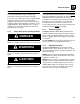
Safety Practices 1.5 SAFETY INFORMATION To avoid possible death or injury, carefully read, understand and comply with all safety messages. In the event of an accident, know where to obtain medical assistance and how to use a first-aid kit and fire extinguisher/fire suppression system. Keep emergency telephone numbers (fire department, ambulance, rescue squad/paramedics, police department, etc.) nearby. If working alone, check with another person routinely to help assure personal safety. 1.
Safety Practices 1.6.3 General Hazards SOLVENTS: Only use approved solvents that are known to be safe for use. appropriate container and dispose of in accordance with prevailing environmental regulations. FIRST AID: Immediately clean, dress and report all injuries (cuts, abrasions, burns, etc.), no matter how minor the injury may seem. Know the location of a First Aid Kit, and know how to use it.
Section 2 General Information and Specifications Contents PARAGRAPH 2.1 2.2 2.3 2.4 2.5 2.6 TITLE Replacement Parts and Warranty Information . . . . . . . . . . . . . . . . . . . . . . . . . . . Torques . . . . . . . . . . . . . . . . . . . . . . . . . . . . . . . . . . . . . . . . . . . . . . . . . . . . . . . . . . 2.2.1 ASTM Fastener Torque Chart (English) . . . . . . . . . . . . . . . . . . . . . . . . . . 2.2.2 ASTM Fastener Torque Chart (Metric) . . . . . . . . . . . . . . . . . . . . . . . . .
General Information and Specifications 2.1 REPLACEMENT PARTS AND WARRANTY INFORMATION Before ordering parts or initiating service inquiries, make note of the machine serial number. The machine serial number plate (1) is located as indicated in the figure. MY1000 1 Note: The replacement of any part on this machine with any other than JLG authorized replacement parts can adversely affect the performance, durability, or safety of the machine, and will void the warranty.
G10-55A & G12-55A AccuPlace 18 24 16 24 14 20 13 20 12 18 11 18 10 16 9 14 8 12 7 12 7 12 6 12 6 12 40 48 32 40 32 36 24 32 20 28 1.5000 1.3750 1.2500 1.1250 1.0000 0.8750 0.7500 0.6250 0.5625 0.5000 0.4375 0.3750 0.3125 IN 0.2500 0.1900 0.1640 0.1380 0.1120 IN BOLT DIA. 0.0524 0.0580 0.0775 0.0878 0.1063 0.1187 0.1419 0.1599 0.1820 0.2030 0.2260 0.2560 0.3340 0.3730 0.4620 0.5090 0.6060 0.6630 0.7630 0.8560 0.9690 1.0730 1.1550 1.3150 1.4050 1.5800 SQ. IN. 0.00604 0.00661 0.
2.4 18 24 16 24 14 20 13 20 12 18 11 18 10 16 9 14 8 12 7 12 7 12 6 12 6 12 40 48 32 40 32 36 24 32 20 28 1.5000 1.3750 1.2500 1.1250 1.0000 0.8750 0.7500 0.6250 0.5625 0.5000 0.4375 0.3750 0.3125 IN 0.2500 0.1900 0.1640 0.1380 0.1120 SQ. IN. IN 0.0524 0.0580 0.0775 0.0878 0.1063 0.1187 0.1419 0.1599 0.1820 0.2030 0.2260 0.2560 0.3340 0.3730 0.4620 0.5090 0.6060 0.6630 0.7630 0.8560 0.9690 1.0730 1.1550 1.3150 1.4050 1.5800 SQ. IN. 0.00604 0.00661 0.00909 0.01015 0.01400 0.01474 0.
General Information and Specifications 2.2.3 Metric Fastener Torque Chart VALUES FOR ZINC PLATED / YELLOW CHROMATE FASTENERS ONLY CLASS 8.8 METRIC BOLTS & CLASS 8 METRIC NUTS SIZE PITCH CLASS 10.9 METRIC BOLTS & CLASS 10 METRIC NUTS TORQUE TENSILE STRESS AREA CLAMP LOAD sq. mm TORQUE DRY OR LOCTITE 263 LUB LOCTITE 262 LOCTITE 242 OR 271 KN N, m N, m N, m N, m CLAMP LOAD DRY OR LOCTITE 263 LUB LOCTITE 262 LOCTITE 242 OR 271 KN N, m N, m N, m N, m 3 .5 5.03 2.19 1.3 1.0 1.
General Information and Specifications 2.3 SPECIFICATIONS 2.3.1 Travel Speeds G10-55A G12-55A First Gear 3.4 mph (5,4 km/h) 3.5 mph (5,6 km/h) Second Gear 6.1 mph (9,8 km/h) 6.3 mph (10,1 km/h) Third Gear 13.8 mph (22,2 km/h) 14.1 mph (22,7 km/h) Fourth Gear 20.0 mph (32,2 km/h) 20.4 mph (32,8 km/h) 2.3.
General Information and Specifications 2.3.4 Tires Note: Standard wheel lug nut torque is 350-400 lb-ft (475-542 Nm). a. G10-55A Size 14.00 x 24 Tire Type Minimum Ply/ Star Rating Fill Type Pressure G-2/L-2 Bias Ply Traction 12 Ply Pneumatic 65 psi (4,5 bar) approx. 720 lb foam 14.00 x 24 G-3/L-3 Bias Ply Rock 12 Ply Pneumatic 65 psi (4,5 bar) approx. 720 lb foam 14.00 x 24 G-2/L-2 Radial 1 Star Pneumatic 70 psi (4,8 bar) approx. 720 lb foam 14.
General Information and Specifications 2.4 FLUID AND LUBRICANT CAPACITIES Engine Crankcase Oil Capacity with Filter Change - Perkins 7 quarts (6,5 liters) Oil Type 15W-40 CE Fuel Tank Capacity 38 gallons (144 liters) Type of Fuel Low Sulfur Diesel #2 Cooling System System Capacity - Perkins 20.5 quarts (19,4 liters) Overflow Bottle Capacity Type of Fluid 3 quarts (2,8 liters) 50/50 ethylene glycol & water Coolant Conditioner (refer engine manual) 0.
General Information and Specifications 2.5 2.5.
General Information and Specifications 2.5.
General Information and Specifications 2.6 LUBRICATION SCHEDULES a. 50 Hour EVERY 50 OY1630 G10-55A & G12-55A AccuPlace 2.
General Information and Specifications b. 250 Hour EVERY 250 OW1210 2.
Section 3 Boom Contents PARAGRAPH 3.1 3.2 3.3 3.4 3.5 3.6 3.7 3.8 3.9 3.10 TITLE Boom System Component Terminology . . . . . . . . . . . . . . . . . . . . . . . . . . . . . . . . Boom System - Four Section . . . . . . . . . . . . . . . . . . . . . . . . . . . . . . . . . . . . . . . . . 3.2.1 Boom System Operation . . . . . . . . . . . . . . . . . . . . . . . . . . . . . . . . . . . . . . Boom Assembly Maintenance . . . . . . . . . . . . . . . . . . . . . . . . . . . . . . . . . . . . . . . . 3.3.
Boom 3.1 BOOM SYSTEM COMPONENT TERMINOLOGY The following illustrations identify the components that are referred to throughout this section. EXTEND CHAINS FOURTH BOOM SECTION THIRD BOOM SECTION SECOND BOOM SECTION FIRST BOOM SECTION ELECTRICAL CONNECTION ATTACHMENT TILT CYLINDER ATTACHMENT QUICK SWITCH BOOM HYDRAULIC ASSEMBLY (Inside Boom) RETRACT CHAINS EXTEND/RETRACT CYLINDER (Underside Of Boom) HOSE SHEAVES MAP0500 3.
Boom 3.2 3.2.1 BOOM SYSTEM - FOUR SECTION Boom System Operation The four section boom consists of the first, second, third and fourth assemblies with double third and fourth section extend chains, a double third section retract chain and a single fourth section retract chain. As the extend/retract cylinder, which is anchored at the front of the second boom section, and the rear of the first boom section begins to extend, it forces the second boom section out of the first boom section.
Boom 3.3.2 Second, Third & Fourth Boom Section Removal 1. Set the complete boom on level ground and by repositioning the slings, turn boom over on to the top side. Set the complete boom on suitable stands to begin tear down. Note: With the complete boom setting upside down, the removal and replacing of each boom section, hoses, extend and retract chains and hose carrier are made much easier. hose ends and tube ends to prevent dirt and debris from entering the hydraulic system. 9.
Boom 9. Loosen and remove all the wear pads from the front of the second boom section. Tag each pad, backing plate, shim and bolts from each location. 4. Loosen and remove the front wear pads and supports from the third boom section. Tag each pad, backing plate, shim and bolts from each location. 10. Place a sling around the third boom section, lift and slowly pull the third and fourth boom sections (7) approximately half way out of the second boom section.
Boom Note: Be certain the hydraulic sub-assembly locks into place on the pin bracket at the bottom of the fourth boom section. 4. Reconnect the hydraulic hoses and any optional circuits. 5. Install the guide bracket and hardware to secure the hydraulic sub-assembly to the front of the boom. 6. Reinstall the hose take-up compression spring. Torque the jam nut to 100 lb-ft. There should be a 1 in. (25 mm) gap from the back of the jam nut to the end of the threads on the hose take-up weldment. 7.
Boom Remove the boom from supports and install the remaining wear pads to the second boom section. Do not shim or tighten bolts at this time. 14. Install the grease fittings for the wear pad and chain roller assembly. 3.3.7 Second Boom Section Installation 1. Install the top, bottom and side rear wear pads onto the second boom section. Do not shim or tighten the bolts and this time. 2. Lubricate the inside of the first boom section on areas where the second boom section wear pads will slide. 3.
Boom 21. Install the top front chain roller (7) to the second and third boom sections. 8 MAP0740 3.3.8 Boom Installation 1. Park the machine on a hard, level surface, place the transmission control lever in (N) NEUTRAL, engage the park brake, chock the wheels and shut the engine OFF. 2. Using suitable slings, balance the boom assembly, lift and carefully guide the boom into place. Align the frame pivot bore with the boom assembly pivot bore. Install the boom pivot pin. 22.
Boom 3.4 3.4.1 BOOM EXTEND AND RETRACT CHAINS Following are some examples of dynamic shock loading which can impose abnormal loads above the endurance limit of a leaf chain. • High velocity movement of load, followed by sudden, abrupt stops. Boom Chain Inspection • Carrying loads in suspension over irregular surfaces such as railroad tracks, potholes, and rough terrain. WARNING Worn pins, stretched or cracked links or corrosive environments can cause chain failure.
Boom Distorted or Battered Link Plates Edge Wear Check the chain for wear on the link plate edges caused by running back and forth over the sheave. The maximum reduction of material should not exceed 5%. Measure and compare to a normal link plate height by measuring a portion of chain that does not run over the sheave. If the measured plate height (1) is 5% less than the normal plate height (2), discard and replace the chain.
Boom Cracked Plates 3.4.3 Inspect the chains very carefully, front and back as well as side to side, for any evidence of cracked plates. If any one crack is discovered, the chain should be replaced in its entirety. It is important, however to determine the cause of the crack before installing a new chain so the condition does not repeat itself. • Stress Corrosion Cracking - The 10 outside link plates are particularly susceptible to stress corrosion cracking (10). 9 1.
Boom 3.4.4 Chain Lubrication After inspection and before being returned to service, chains must be lubricated with a quality chain lubricant (“LUBRIPLATE” Chain & Cable Fluid, “LPS3” or equivalent). The lubricant must penetrate the chain joint to prevent wear. Applying lubricant to the external surfaces will prevent rust, but the chains should be articulated to make sure the lubricant penetrates to the working surfaces between the pins and links.
Boom 3.4.6 Retract Chain Installation Inspect and lubricate chains thoroughly before installation. Articulate the chains to make sure all working surfaces are thoroughly lubricated. Note: If the inner retract chain was removed, it must be installed first. 1. Fasten a rope to the end of the 3/4 in. chain in order to pull it back into the boom. 2. Attach the chain to the chain clevis at the rear of the boom. 3. Carefully pull the chain into the boom until it can be fastened to the chain clevis. 4.
Boom 3.5 BOOM SECTION SEPARATION ADJUSTMENT 1 1. Park the machine on level ground. Place the transmission control lever in (N) NEUTRAL, engage the parking brake switch and raise the boom to a horizontal (level) position. 2. Extend the boom 4 ft to 5 ft, then fully retract the boom. 3. Measure the gap between the flat washer at the extend chain anchor on the top front of the first boom section and the second boom section. If the gap is greater that 3/8 in. (9.
Boom 2. Park the machine on a hard, level surface, level the machine, fully retract the boom, level the boom, place the transmission control lever in (N) NEUTRAL, engage the park brake and shut the engine OFF. 10. Loosen and remove the sub-assembly bracket (4) at the rear of the third boom section. 3. Place a Do Not Operate Tag on both the ignition key switch and the steering wheel, stating that the machine should not be operated. 4 4. Open the engine cover. Allow the system fluids to cool. 1 5.
Boom 3.6.2 Assembling the Hydraulic SubAssembly The following procedure is described with the assumption that all components have been removed and assembly proceeding from the beginning. 3. Fully collapse the hose carriers and secure together using plastic tie wraps or nylon straps to keep them from separating. 4. Install a sling around the balance point of the subassembly. With a suitable lifting device, slowly insert the sub-assembly into the front of the fourth boom section. 5.
Boom 3.7 BOOM WEAR PADS The wear pads on this machine are flat rectangular wear pads with metal inserts. A total of 42 wear pads are installed on the boom. 3.7.1 Wear Pad Inspection Inspect all wear pads for wear. If the angle indicators (3) on the ends of the wear pads are visible, the wear pads can be reused. If the pads show uneven wear (front to back), they should be replaced. Replace pads as a set if worn or damaged. 4 3 3 Ma2070 3.7.
Boom 3.8 3.8.1 QUICK SWITCH ASSEMBLY Quick Switch Removal 1. Remove the lock bolt holding the tilt cylinder rod end pin to the quick switch assembly. Remove the Tilt Cylinder pin. 2. Support the quick switch assembly.Remove the capscrew and locknut securing the head pin to the boom head. 3. Inspect the above pins for nicks or surface corrosion. Use fine emery cloth to fix minor nicks or corrosion. If damaged or if it cannot be repaired, the pin must be replaced. 3.8.2 Quick Switch Installation 1.
Boom 3.10 TROUBLESHOOTING This section provides an easy reference guide covering the most common problems that occur during operation of the boom. Problem 1. Boom will not extend or retract. Cause Remedy 1. Broken hydraulic hose(s) or tube(s) and/or connections leaking. 1. Locate break, replace hose(s) or tube(s), tighten connections. 2. Extend/retract hydraulic system not operating properly. 2. Refer to Section 8.4, “Hydraulic Circuits.” 3. Faulty extend/retract cylinder. 3. Repair cylinder.
Boom Problem 4. Drooping chain, or jerky boom extend or retract functions. 5. Boom will not raise or lower. 6. Excessive Lift/Lower cylinder pivot pin noise and/or wear. 3.20 Cause Remedy 1. Chain(s) tension not properly adjusted. 1. Adjust chain(s). 2. Chain(s) stretched or binding. 2. Replace chains as needed. Refer to Section 3.5, “Boom Section Separation Adjustment.” 3. Wear pads loose, contaminated, excessively worn or damaged. 3. Replace wear pad. Refer to Section 3.7.
Boom Problem 7. Rapid boom pad wear. 8. Auxiliary hydraulics will not operate. 9. Excessive chain wear. G10-55A & G12-55A AccuPlace Cause Remedy 1. Incorrect wear pad gap. 1. Check wear pad gaps and correct as needed. Refer to Section 3.7.2, “Boom Wear Pad Replacement.” 2. Rapid cycle times with heavy loads. 2. Reduce cycle times. 3. Contaminated, corroded or rusted wear pad sliding surfaces. 3. Remove contamination and/or corrosion from wear pad sliding surfaces and lubricate.
Boom This Page Intentionally Left Blank 3.
Section 4 Cab and Covers Contents PARAGRAPH 4.1 4.2 4.3 4.4 4.5 TITLE Operator’s Cab and Covers Component Terminology . . . . . . . . . . . . . . . . . . . . Operator’s Cab . . . . . . . . . . . . . . . . . . . . . . . . . . . . . . . . . . . . . . . . . . . . . . . . . . . . 4.2.1 Cab Safety . . . . . . . . . . . . . . . . . . . . . . . . . . . . . . . . . . . . . . . . . . . . . . . . 4.2.2 Serial Number Decal . . . . . . . . . . . . . . . . . . . . . . . . . . . . . . . . . . . . . . . .
Cab and Covers 4.1 OPERATOR’S CAB AND COVERS COMPONENT TERMINOLOGY To understand the safety, operation and maintenance information presented in this section, it is necessary that the operator/mechanic be familiar with the names and locations of the major assemblies of the machine cab and covers. The following illustration identifies the components that are referred to throughout this section.
Cab and Covers 4.2 OPERATOR’S CAB WARNING DO NOT service the machine without following all safety precautions as outlined in the “Safety Practices” section of this manual. Failure to follow the safety practices could result in death or serious injury. 4.2.1 Cab Safety WARNING 3. Open the engine cover. Allow the system fluids to cool. 4. Remove the battery negative (-) cable at the battery negative (-) terminal.
Cab and Covers b. Orbitrol Valve Installation 1. Secure the steering valve to the steering column with four hex-flange capscrews and four lockwashers. Apply Loctite® 242 threadlock to the capscrews threads before tightening. 2. Install the steering column through the dash panel opening. Position steering valve to its original orientation in the cab. 3. Install the travel select lever. Torque the capscrews to 30-35 lb-in (3,4-4 Nm).
Cab and Covers 3. Be sure the brake pedal has the correct range of motion. Secure pivot pin with bolt and lockwasher. Apply Loctite® 242 threadlock to the bolt threads before tightening. Note: If necessary, install the dash to the cab by installing the three bolts, nuts and washers. 1. Position the throttle pedal in its mounting location within the cab. 2. Secure the throttle pedal into position with the pivot pin. 3. Install the throttle pedal ball joint to the throttle pedal. 4.
Cab and Covers b. Boom Joystick Assembly Installation 1. Connect the electrical harness connector to the joystick. 2. Ensure the rubber sleeve at the base of the joystick is secured over all four corners of the base of the joystick. If necessary, carefully pull the rubber sleeve over the four corners. 3. Place the joystick into the mount and install the bolts securing the boom joystick to the cab. Ensure the rubber sleeve on the joystick stays in place when tightening the bolts. 4.
Cab and Covers 9. Remove the bolts that secure the seat to the cab. Remove the seat. 4. Install the seat riser weldment. 5. Install the front plate to the seat riser weldment. 6. Install the cab seat. 7. Fill the cooling system completely with a 50/50 mixture of ethylene glycol and water, allowing time for the coolant to fill the engine block. The cooling system capacity is listed in Section 2.4, “Fluid and Lubricant Capacities.” 12 11 MY0190 10.
Cab and Covers 2. Block all four wheels to help prevent the machine from moving. Ensure that there is sufficient overhead and side clearance for cab removal. 3. Open the engine cover. Allow the system fluids to cool. 4. Disconnect the battery negative (-) cable at the battery negative (-) terminal. the cab so they do not become damaged during cab removal. 18. Remove the fuel tank from the cab. Refer to Section 7.4.2, “Fuel Tank.” 19.
Cab and Covers 24. When all wiring, hydraulic hoses and fasteners are disconnected or removed, carefully and slowly lift the cab and remove it from the frame. Readjust the position of the sling as needed to help balance the cab during removal. 25. When the cab is completely clear of the machine, carefully lower it to the ground. Block up or support the cab so that it does not move or fall. Ensure that no personnel enter the cab while it is being removed from the machine. 26.
Cab and Covers This Page Intentionally Left Blank 4.
Section 5 Axles, Drive Shafts, Wheels and Tires Contents PARAGRAPH 5.1 5.2 5.3 5.4 5.5 5.6 5.7 TITLE Axle, Drive Shaft and Wheel Component Terminology . . . . . . . . . . . . . . . . . . . . General Information . . . . . . . . . . . . . . . . . . . . . . . . . . . . . . . . . . . . . . . . . . . . . . . . Axle Assemblies . . . . . . . . . . . . . . . . . . . . . . . . . . . . . . . . . . . . . . . . . . . . . . . . . . . 5.3.1 Axle Serial Number Plate . . . . . . . . . . . . . . . . . . . . . . . . .
Axles, Drive Shafts, Wheels and Tires 5.1 AXLE, DRIVE SHAFT AND WHEEL COMPONENT TERMINOLOGY To understand the safety, operation and maintenance information presented in this section, it is necessary that the operator/mechanic be familiar with the names and locations of the major assemblies of the axles, drive shafts, wheels and tires. The following illustration identifies the components that are referred to throughout this section.
Axles, Drive Shafts, Wheels and Tires 5.2 GENERAL INFORMATION WARNING DO NOT service the machine without following all safety precautions as outlined in Section 1, “Safety Practices,” of this manual. Failure to follow the safety practices could result in death or serious injury. Note: To help ensure optimum performance, the drive shaft assemblies are specially balanced as a unit at the factory.
Axles, Drive Shafts, Wheels and Tires 5.3.5 Axle Removal The front and rear axle assemblies differ in that the front axle assembly is equipped with a parking brake mechanism and a limited-slip feature; the rear axle has neither. The following steps outline a typical axle removal procedure, suitable for either the front or the rear axle assembly. 8. Block the front and rear of both tires on the axle that is not being removed.
Axles, Drive Shafts, Wheels and Tires 4. Position the axle under the frame, and align the axle housings with the holes in the frame. Note: ALWAYS use new o-rings when servicing the machine. 5. Install the four axle bolts and nuts. Apply Loctite® 242 threadlock to the bolt threads and torque to 530-565 lbft (718-766 Nm). 16. Install new o-rings into the fittings. Lubricate the o-rings with clean hydraulic oil. 6. Move the cylinder into position on the axle cylinder anchor.
Axles, Drive Shafts, Wheels and Tires 5.3.7 Axle Assembly and Drive Shaft Troubleshooting Problem 1. Excessive axle noise while driving. 2. Intermittent noise when traveling. 3. Vibration or intermittent noise when traveling. 5.6 Cause Remedy 1. Oil level too low. 1. Fill oil to correct level. Refer to Section 2.4, “Fluid and Lubricant Capacities.” 2. Axle and/or wheel end housings filled with incorrect oil or oil level low. 2.
Axles, Drive Shafts, Wheels and Tires Problem 4. Oil leaking from axle (differential housing and/or axle housings). 5. Oil leaking from wheel end housing (planet carrier). 6. Oil leaking from steering cylinder. G10-55A & G12-55A AccuPlace Cause Remedy 1. Drain and/or inspection plugs loose and/or o-rings damaged or missing. 1. Replace o-rings as needed and tighten plugs to 96 lb-ft (130 Nm). 2. Hose fittings loose. 2. Tighten fittings. 3.
Axles, Drive Shafts, Wheels and Tires Problem 7. Axle overheating. 8. High steering effort required. 9. Slow steering response. 10. Excessive noise when brakes are engaged. 11. Brakes will not engage. 12. Brakes will not hold the machine or braking power reduced. 5.8 Cause Remedy 1. Oil level too high. 1. Fill oil to correct level with Mobilfluid 424® (ISO 46). Refer to Section 2.4, “Fluid and Lubricant Capacities.” 2.
Axles, Drive Shafts, Wheels and Tires 5.4 5.4.1 DRIVE SHAFTS Drive Shaft Inspection and Service Whenever servicing the machine, conduct a visual inspection of the drive shafts and cross and bearing assemblies (universal joints, or U-joints). A few moments spent doing this can help prevent further problems and down time later. 7. Remove the four capscrews and two straps securing the bearing cross to the transmission output shaft flange. 8.
Axles, Drive Shafts, Wheels and Tires 5.5 WHEELS AND TIRES 4 WARNING Risk of death or serious personal injury. Mismatched tire sizes, ply ratings or mixing of tire types (radial tires with bias-ply tires) may compromise machine stability and could cause machine to tip over. JLG recommends a replacement tire to be the same size, ply and brand as originally installed. Refer to the appropriate parts manual for ordering information.
Axles, Drive Shafts, Wheels and Tires 5.5.2 Installing Wheel and Tire Assembly onto Machine Note: The wheel and tire assemblies must be installed with the directional tread pattern “arrows” facing in the direction of forward travel. 5.6 Check the brake disks for wear every 1,000 hours of operation or yearly. For more information on brake disk inspection, refer to the appropriate axle repair manual. 5.
Axles, Drive Shafts, Wheels and Tires 5.7.2 Manually Resetting the Park Brake Note: Block the wheels of the machine BEFORE attempting to reset the machine’s park brake. Once the park brake is released, the machine’s park brake AND service brakes are inoperable. 1. Loosen each release screw, only 1/4 turn at a time, in sequence, until each screw has lost contact with the guide pin. 2. Remove the screws along with the nuts and seals.
Section 6 Transmission Contents PARAGRAPH 6.1 6.2 6.3 6.4 6.5 6.6 TITLE Transmission Assembly Component Terminology . . . . . . . . . . . . . . . . . . . . . . . Transmission Description . . . . . . . . . . . . . . . . . . . . . . . . . . . . . . . . . . . . . . . . . . . Transmission Serial Number . . . . . . . . . . . . . . . . . . . . . . . . . . . . . . . . . . . . . . . . . Transmission Specifications . . . . . . . . . . . . . . . . . . . . . . . . . . . . . . . . . . . . . . . . . 6.4.
Transmission 6.1 TRANSMISSION ASSEMBLY COMPONENT TERMINOLOGY To understand the safety, operation and maintenance information presented in this section, it is necessary that the operator/mechanic be familiar with the names and locations of the major assemblies of the transmission. The following illustration identifies the components that are referred to throughout this section.
Transmission 6.4.2 WARNING Complete transmission maintenance information is located in the appropriate Operation & Safety Manual. DO NOT service the machine without following all safety precautions as outlined in Section 1, “Safety Practices,” of this manual. Failure to follow the safety practices could result in death or serious injury. 6.2 6.3 TRANSMISSION SERIAL NUMBER The transmission serial number plate is located on the front of the transmission case behind the oil dipstick.
Transmission 6.5.1 Transmission Removal WARNING Risk of severe personal injury. NEVER lift a transmission alone; enlist the help of at least one assistant or use a suitable hoist or overhead crane and sling. 9. Transfer the used transmission oil into a suitable, covered container, and label the container as “Used Oil.” Dispose of used oil at an approved recycling facility. Clean and reinstall the transmission drain plug. 10. Remove the transmission-to-axle drive shafts. Refer to Section 5.4.
Transmission 26. Remove any external transmission components as required, including the transmission temperature switch, and inlet and outlet cooler hose fittings. Cover all transmission openings. 3 2 MAP0690 27. Remove the transmission oil filter (3) and dispose of properly. Clean the filter mounting surface. Cover or cap the oil filter mount. orientation with one hole at 6 o’clock on the engine and the transmission. 6. Install the twelve bolts and washers and torque to 53 lb-ft (72 Nm).
Transmission 6.5.4 After Transmission Service or Replacement Refer to the ZF Transmission Repair Manual PN- 5872 135 002 (JLG P/N 31200241) which can be obtained by calling your local JLG distributor. In general: 1. Check the transmission oil level and add oil as required. 2. Install a new transmission filter. 3. Check the torque on the drive shaft yoke capscrews. 4. Wear suitable eye protection.
Transmission 6.6 TROUBLESHOOTING This section provides an easy reference guide covering the most common problems that may occur during operation of the transmission. Note: Contact the JLG Service Department if internal transmission repair is required during the warranty period. The transmission should be checked, serviced and repaired only by experienced service technicians who are aware of all safety instructions and particular component features. 6.6.1 Transmission Troubleshooting Problem 1.
Transmission Problem 2. Low or no pump flow or pressure. 3. Low clutch pressure. 6.8 Cause Remedy 1. Low oil level. 1. Fill transmission to correct level with Mobilfluid 424® (ISO Grade 46). Refer to Section 2.4, “Fluid and Lubricant Capacities.” 2. Transmission filled with incorrect oil, or oil contaminated. 2. Drain transmission and fill to correct level with Mobilfluid 424® (ISO Grade 46). Refer to Section 2.4, “Fluid and Lubricant Capacities.” 3. Pump suction pipe screen clogged. 3.
Transmission Problem 4. Lack of power. 5. Transmission overheating (oil above 120° C (248° F)). G10-55A & G12-55A AccuPlace Cause Remedy 1. Park or service brake dragging. 1. Refer to Section 8.4, “Hydraulic Circuits.” 2. Low engine rpm causes converter stall. 2. Adjust the engine rpm to specifications. Refer to Engine Service Manual. 3. Pump output pressure is low. 3. Refer to Section 6.6.1, “Transmission Troubleshooting,” Problem 2. “Low or no pump flow or pressure.” 4.
Transmission Problem 6. Grinding or “clunking” noise from transmission. 6.10 Cause Remedy 1. Oil level too low. 1. Fill oil to correct level. Refer to Section 2.4, “Fluid and Lubricant Capacities.” 2. Transmission filled with incorrect oil. 2. Drain transmission and fill to correct level with Mobilfluid 424® (ISO Grade 46). Refer to Section 2.4, “Fluid and Lubricant Capacities.” 3. Incorrect clutch engagement. 3. Refer to Section 9.11.8, “Transmission Solenoid Valves.” 4. Internal damage. 4.
Transmission Problem 7. Oil leaking from transmission. G10-55A & G12-55A AccuPlace Cause Remedy 1. Oil leaking from vent (high oil level). 1. Remove drain plug and drain oil as needed, until oil is at correct level. Refer to Section 2.4, “Fluid and Lubricant Capacities.” Replace o-rings as needed and tighten plugs to 96 lb-ft (130 Nm). 2. Drain plug loose and/or o-rings damaged or missing. 2. Replace o-rings as needed and tighten plug to 26 lb-ft (35 Nm). 3. Hose fittings loose. 3.
Transmission This Page Intentionally Left Blank 6.
Section 7 Engine Contents PARAGRAPH 7.1 7.2 7.3 7.4 7.5 7.6 7.7 7.8 7.9 TITLE Introduction . . . . . . . . . . . . . . . . . . . . . . . . . . . . . . . . . . . . . . . . . . . . . . . . . . . . . . . 7.1.1 Disclaimer and Scope . . . . . . . . . . . . . . . . . . . . . . . . . . . . . . . . . . . . . . . . 7.1.2 Component Terminology . . . . . . . . . . . . . . . . . . . . . . . . . . . . . . . . . . . . . . 7.1.3 Engine Serial Number . . . . . . . . . . . . . . . . . . . . . . . . . . . . . . . .
Engine 7.1 7.1.1 INTRODUCTION Disclaimer and Scope These instructions are written for worldwide use. In territories where legal requirements govern engine smoke emission, noise, safety factors, etc., apply all instructions, data and dimensions provided herein in such a way that after maintenance, service and repair of the engine, engine operation does not violate local regulations. Note: These instructions cover only the routine maintenance, removal, installation and troubleshooting of the engine.
Engine 7.1.2 Component Terminology To understand the safety, operation and maintenance information presented in this section, it is necessary that the operator/mechanic be familiar with the names and locations of the engine components. The following illustration identifies the components that are referred to throughout this section. THERMOSTAT FUEL FILTER OIL FILTER STARTER MAL0260 ALTERNATOR MAL0270 G10-55A & G12-55A AccuPlace 7.
Engine 7.1.3 Engine Serial Number a. Thermostat Removal The Perkins 1104D serial number is stamped on top of the engine. Information contained in the serial number is required in correspondence with the engine manufacturer. 1. Park the machine on a firm, level surface, level the machine, fully retract the boom, lower the boom, place the travel select lever in the (N) NEUTRAL position, engage the parking brake, and shut the engine OFF. 7.1.4 2.
Engine b. Thermostat Installation 1. Install the engine thermostat, thermostat gasket and thermostat housing. Secure with the two capscrews. 2. Connect the Engine Water Temperature sender. 3. Connect the battery negative (-) cable to the battery negative (-) terminal. 4. Open the radiator cap, and fill the radiator completely with a 50/50 mixture of ethylene glycol and water. Replace and tighten the radiator cap. Add coolant to the overflow bottle until the bottle is 1/4 to 1/2 full.
Engine b. Radiator Installation 1. Install the isolator mounts to the bottom of the radiator. Place the radiator in the engine compartment at its original orientation. Secure with the previously used hardware. Note: Ensure there is adequate clearance between the radiator and the engine fan. 2. If necessary, install the engine fan. 3. Install the radiator fan shroud. 4. Uncap and connect the previously labeled hoses to the radiator and oil cooler. 5. Install the coolant recovery tank.
Engine 7.4.2 Fuel Tank Note: The fuel tank is a one piece unit. It is located on the rear of the cab. If it is determined that the fuel tank must be removed, the fuel must be drained before tank removal. Always dispose of fuel properly. a. Fuel Tank Removal 1. Park the machine on a firm, level surface, level the machine, fully retract the boom, lower the boom, place the travel select lever in the (N) NEUTRAL position, engage the parking brake, and shut the engine OFF. 2.
Engine 6. Fill the fuel tank according to specifications. Refer to Section 2.4, “Fluid and Lubricant Capacities.” 7. Check fuel tank for leaks. 7.5.2 Exhaust System Installation Note: Keep all clamps loosened until entire exhaust system is in place. 8. Connect the battery negative (-) cable to the battery negative (-) terminal. 9. Close and secure the engine cover. 7.4.3 After Fuel System Service 1. Drain and flush the fuel tank if it was contaminated. 2.
Engine 7.6 AIR CLEANER ASSEMBLY CAUTION NEVER run the engine with only the inner safety element installed. Note: Refer to the appropriate Operation & Safety Manual for your machine for the correct element change procedure. 7.6.1 Air Cleaner Assembly Removal 1. Park the machine on a firm, level surface, level the machine, fully retract the boom, lower the boom, place the travel select lever in the (N) NEUTRAL position, engage the parking brake, and shut the engine OFF. 2.
Engine 7.7.2 Engine Installation 1. Attach a lifting chain to the front and rear engine lift brackets, and lift engine clear of the ground. Note: Apply Loctite® 242 threadlock to the engine mount bracket capscrew threads before installation. 2. Install two guide studs in the bell housing holes. 3. Lift the engine and slowly push and lower into the engine bay. Have an assistant ensure that the engine clears the frame, hose and harness components during engine installation.
Engine 18. Install the battery and connect the (+) positive and (-) negative cables. 7.8 19. Check that all hydraulic system, electrical system, cooling system, fuel system and exhaust system connections are correct and connected tightly. 7.8.1 20. From within the cab, lightly depress the throttle pedal to full-throttle position. As needed, adjust the limitstop screw until it touches the pedal bracket. Note: Have an assistant stand by with a Class B fire extinguisher. 21.
Engine 7.
Section 8 Hydraulic System Contents PARAGRAPH 8.1 8.2 8.3 8.4 8.5 8.6 8.7 8.8 8.9 8.10 TITLE Hydraulic Component Terminology. . . . . . . . . . . . . . . . . . . . . . . . . . . . . . . . . . . . Safety Information. . . . . . . . . . . . . . . . . . . . . . . . . . . . . . . . . . . . . . . . . . . . . . . . . . Hydraulic Pressure Diagnosis . . . . . . . . . . . . . . . . . . . . . . . . . . . . . . . . . . . . . . . . 8.3.1 Pressure Checks and Adjustments . . . . . . . . . . . . . . . . . . . . . .
Hydraulic System 8.1 HYDRAULIC COMPONENT TERMINOLOGY To understand the safety, operation and service information presented in this section, it is necessary that the operator/mechanic be familiar with the name and location of the hydraulic components of the machine. The following illustration identifies the components that are referred to throughout this section.
Hydraulic System 8.2 SAFETY INFORMATION WARNING DO NOT service the machine without following all safety precautions as outlined in Section 1, “Safety Practices,” of this manual. Failure to follow the safety practices could result in death or serious injury. Petroleum-based hydraulic fluids are used in this machine. The temperature of hydraulic fluid increases during the operation of various hydraulic functions.
Hydraulic System 8.3 HYDRAULIC PRESSURE DIAGNOSIS JLG Parts Department has a kit available to use for hydraulic system maintenance and troubleshooting: the JLG Pressure Test Kit. The kit is contained in a durable polyethylene carrying case for demanding field service conditions. Pressure Test Kit The hydraulic pressure test kit is used to pressure test the various hydraulic components in the hydraulic system.
Hydraulic System 8.4 HYDRAULIC CIRCUITS This section covers the hydraulic circuits and includes listings for all hydraulic function pressures, where and how to check those pressures and a hydraulic schematic. Electrical and hydraulic functions are often related. Verify that the electrical components of the circuit are functioning properly whenever troubleshooting the hydraulic circuit. machine off, install the safety cap and remove the gauge from the test port. 4.
Hydraulic System c. Pressure Specifications Hydraulic Circuit Test Port Adjustment Location Function Used to Test Pressure Range System Relief G1 Refer to Section 8.4.1, “Hydraulic Pressures.
Hydraulic System 8.5 8.5.1 HYDRAULIC SYSTEM SCHEMATICS AND DIAGRAMS Chassis Schematic MAP0310 D G10-55A & G12-55A AccuPlace 8.
Hydraulic System 8.5.2 Boom Schematic MAP0320 D 8.
Hydraulic System 8.5.3 Hydraulic Diagram MAP0600 F G10-55A & G12-55A AccuPlace 8.
Hydraulic System 8.5.3 Hydraulic Diagram (Continued) MAP0610 F 8.
Hydraulic System 8.5.3 Hydraulic Diagram (Continued) MAP0620 F G10-55A & G12-55A AccuPlace 8.
Hydraulic System 8.6 HYDRAULIC RESERVOIR 8.6.3 The hydraulic reservoir (1) is located on the frame between the engine compartment and the cab. 1 2 Hydraulic Oil Reservoir Removal/ Installation If it is determined that the hydraulic oil reservoir must be removed, the hydraulic oil must be drained before the reservoir is removed. Always dispose of hydraulic oil properly. a. Reservoir Removal 1.
Hydraulic System To clean the hydraulic oil reservoir: 1. Have a dry chemical (Class B) fire extinguisher near the work area. 8.7 ENGINE IMPLEMENT PUMP 8.7.1 Pump Description 2. Remove the hydraulic oil reservoir drain plug, and safely drain any hydraulic oil into a suitable container. Dispose of hydraulic oil properly. For internal service instructions contact your local JLG distributor. 3.
Hydraulic System 7. Label, disconnect and cap the hydraulic hoses attached to the pump. 8. Connect a hose to the “P1” port on the pump. Direct the open end of the hose into a fluid drip pan. 9. Turn the machine ignition switch to START and back OFF in 3 to 5 second intervals. Monitor the open end of the drain hose for a constant flow of fluid (no air) while engine is cranking. 1 10.
Hydraulic System 5. Thoroughly clean the valve and surrounding area, including all hoses and fittings before proceeding. 8.8.2 6. Label, disconnect and cap the hydraulic hoses attached to the lift valve (1) and lift manifold (2). Cap all fittings to prevent dirt & debris from entering the hydraulic system. a. ISP Valve Removal 7. Label and disconnect the electrical connectors from the lift valve. ISP Valve 4 8.
Hydraulic System 4. Uncap and connect the previously labeled hydraulic hoses to their appropriate locations. 8. Label and disconnect the electrical connectors from the stabilizer valve. 5. Connect the battery negative (-) cable to the battery negative (-) terminal. 9. Remove the hardware securing the stabilizer valve to the machine frame. 6. Before starting the machine, check fluid level of the hydraulic fluid reservoir and if necessary fill to full mark with Mobilfluid 424® (ISO 46). 7.
Hydraulic System Note: This will ensure that there is approximately a 325 psi (22 bar) margin between the valve LS and pump output. 8.8.4 Auxiliary Valve 3. Uncap and connect the previously labeled hydraulic hoses to their appropriate locations. 4. Connect the battery negative (-) cable to the battery negative (-) terminal. 5. Before starting the machine, check fluid level of the hydraulic fluid reservoir and if necessary fill to full mark with Mobilfluid 424® (ISO 46). a. Auxiliary Valve Removal 8 6.
Hydraulic System 8. If necessary, remove the telescope valve controller from the telescope valve. 8. Label and disconnect the electrical connectors from the tilt valve (12). b. Telescope Valve Installation 1. If necessary, install the telescope valve controller to the telescope valve with the previously used hardware. Refer to Section 8.8.11, “Valve Controllers,” for proper torque values and sequence. 2. Install the telescope valve to the extend cylinder with the previously used hardware. 12 3.
Hydraulic System 5. Uncap and connect the previously labeled hydraulic hoses to their appropriate locations. 4. Disconnect the battery negative (-) cable from the battery negative (-) terminal. 6. Connect the previously labeled electrical connectors to the tilt valve. 5. Label, disconnect and cap all hoses attached to the Service Brake valve (13). 7. Connect the battery negative (-) cable to the battery negative (-) terminal. 6. Remove the service brake pedal. Refer to Section 4.3.
Hydraulic System the brakes to apply properly. There are four brake bleeder locations on the axles. Work with an assistant to perform this procedure. 15 1. Place the travel select lever in (N) NEUTRAL, engage the park brake, and start the engine. 2. Remove the plastic cap from the brake bleeder (14). Attach one end of a length of transparent tubing over the brake bleeder. Place the other end of this tubing in a suitable transparent container that is partially filled with hydraulic oil.
Hydraulic System 3. Open the engine cover. Allow the system fluids to cool. c. Steer Select Valve and Manifold Installation 4. Disconnect the battery negative (-) cable from the battery negative (-) terminal. 1. Install the steer select valve to the mounting plate on the underside of the frame near the transmission using the two bolts. 5. Label, disconnect and cap the hydraulic hoses and the electrical plugs connected to the steering select valve. 2.
Hydraulic System 8.8.11 2. Place a Do Not Operate Tag on both the ignition key switch and the steering wheel, stating that the machine should not be operated. Valve Controllers CAUTION HIGH OIL PRESSURE WITHIN VALVE AND CONTROLLER. Removing the controller may cause cylinder leakage. Brace and block the boom before removing lift valve and telescope valve controllers. Valve controllers (7) are located on the following valves: Lift Valve, ISP Valve, Telescope Valve and Tilt Valve.
Hydraulic System 6. Before starting the machine, check fluid level of the hydraulic fluid reservoir and if necessary fill to full mark with Mobilfluid 424® (ISO 46). 7. Start the machine and run at low idle for about one minute. Test the functions of the accumulator and lift valve. 8. Inspect for leaks and check level of hydraulic fluid in reservoir. Add hydraulic fluid if needed. Shut the engine OFF. 9. Close and secure the engine cover. 8.9.
Hydraulic System valve, then slowly open the bleed valve. Do not reduce the pre-charge by depressing the valve core with a foreign object. High pressure may rupture the rubber valve seat. 15. When finished pre-charging the accumulator, turn the handle all the way out on the gas chuck, then open the bleed valve. 16. Remove the fill kit assembly from the gas valve on the accumulator. Check for precharge leak using a common leak reactant. 17. Replace the gas valve cap and valve guard.
Hydraulic System slide the head gland down along the rod toward the rod eye, away from the cylinder barrel. Note: When sliding the rod and piston assembly out of the barrel, prevent the threaded end of the barrel from damaging the piston. Keep the rod centered within the barrel to help prevent binding. 6. Carefully pull the rod assembly along with the head gland out of the cylinder barrel. 7.
Hydraulic System 6. Carefully insert the cylinder rod assembly into the cylinder barrel. 7. Screw the head gland into the cylinder barrel and tighten with a spanner wrench. Refer to Section 8.10.4, “Cylinder Torque Specifications” for torque specifications for the head gland. 8. If applicable, install new counter balance valve into block on the cylinder barrel. 8.10.3 Steering Cylinders The steer cylinder is attached to each axle center housing.The steer cylinder assembly can be found in Section 5.
Hydraulic System 8.10.4 Cylinder Torque Specifications a. Lift/Lower Cylinder Model Head Nut Valve Valve Screw G10-55A 275 lb-ft min (373 Nm) 1600-2000 lb-ft (2169-2712 Nm) 45-50 lb-ft (54-61 Nm) 28-30 lb-ft (38-41 Nm) G12-55A 300 lb-ft min (407 Nm) 1600-2000 lb-ft (2169-2712 Nm) 45-50 lb-ft (54-61 Nm) 28-30 lb-ft (38-41 Nm) b. Extend/Retract Cylinder Head Nut Valve (Large) Valve (Small) 250 lb-ft min (339 Nm) 1898-2305 lb-ft (1400-1700 Nm) 110 lb-ft (149 Nm) 35 lb-ft (47 Nm) c.
Hydraulic System This Page Intentionally Left Blank 8.
Section 9 Electrical System Contents PARAGRAPH 9.1 9.2 9.3 9.4 9.5 9.6 9.7 9.8 9.9 9.10 9.11 TITLE Electrical Component Terminology . . . . . . . . . . . . . . . . . . . . . . . . . . . . . . . . . . . . 9.1.1 General Overview . . . . . . . . . . . . . . . . . . . . . . . . . . . . . . . . . . . . . . . . . . . Specifications . . . . . . . . . . . . . . . . . . . . . . . . . . . . . . . . . . . . . . . . . . . . . . . . . . . . . Safety Information. . . . . . . . . . . . . . . . . . . . . . . . . . .
Electrical System 9.12 9.13 9.14 9.15 9.2 9.11.9 Transmission Temperature Sender . . . . . . . . . . . . . . . . . . . . . . . . . . . . . . 9.11.10 Engine Coolant Temperature Sender / Switch . . . . . . . . . . . . . . . . . . . . . 9.11.11 Fuel Level Sender . . . . . . . . . . . . . . . . . . . . . . . . . . . . . . . . . . . . . . . . . . . 9.11.12 Boom Angle Sensors . . . . . . . . . . . . . . . . . . . . . . . . . . . . . . . . . . . . . . . . 9.11.13 Boom Length Sensor . . . . . . . . . . . . . .
Electrical System 9.1 ELECTRICAL COMPONENT TERMINOLOGY To understand the safety, operation, and service information presented in this section, it is necessary that the operator/mechanic be familiar with the name and location of the electrical components of the machine. The following illustration identifies the components that are referred to throughout this section. 9.1.
Electrical System 9.2 SPECIFICATIONS 9.4 FUSES AND RELAYS Electrical system specifications are listed in Section 2, “General Information and Specifications.” 9.4.1 9.3 The starter relay (1), glow plug relay (2), 50 amp fuse (3) and power distribution unit (4) are located on the power distribution unit bracket in the engine compartment.
Electrical System 9.4.3 Power Distribution Unit (VEC) F8 F3 CB3 F4 CB4 CB2 F9 F7 F10 F11 IGN1 CB1 F1 IGN3 ACCY1 F12 F5 F6 F2 ACCY2 MY1250 Connector Legend No.
Electrical System 9.4.4 Optional Power Distribution Unit (VEC) F1 R1 F2 F3 R2 F4 F5 R3 F6 F7 R4 F8 R5 R6 R7 R8 MY1260 Connector Legend 9.6 No.
Electrical System 9.5 9.5.1 CONTROL MODULES b. Disassembly CAN Distribution Module The CAN Distribution Module (1) is located at the rear of the machine between the boom masts. 1 DO NOT disassemble the CAN Module other than removing the cover. The module is not serviceable. Replace the module if found to be defective. c. CAN Module Installation 1. If removed, install the cover on the CAN Module. 2 2. Attach the CAN Module to the mounting bracket with the appropriate hardware. 3.
Electrical System d. CAN Module Connections MAP0530 CAN Module Harness Connector Legend No. Description 1 Lift Valve Cable Connector 2 Tele-Valve Cable Connector 3 Boom Angle Sensor Cable Connector 4 Boom Length Cable Connector 5 Chassis Harness Connector 6 Not Used CAN Module Terminal Connector Legend 9.8 No. Amp Rating V+ 8 V+ 4 (additional as power splice) V- 8 V- 4 (additional as power splice) CANS 3.2 CANL 3.2 CANH 3.2 V+P3 3.2 V+P4 3.2 V+P5 3.2 V+P6 3.2 J1 3.
Electrical System 9.5.2 Universal Ground Control Module (UGM) The UGM is located behind the right hand side panel (3) where the joysticks are located. b. Disassembly DO NOT disassemble the UGM. The module is not serviceable. Replace the module if found to be defective. c. Inspection and Replacement Inspect the module terminals for continuity. Replace the module if continuity is not found. d. UGM Installation 1. Attach the UGM to the cab with the previously removed hardware. 3 2.
Electrical System e. UGM Connections J8 J1 J7 J12 J2 J3 J4 MAP0540 a. UGM Inputs UGM Connector/Pin 9.
Electrical System UGM Connector/Pin Description Description/Purpose J4-35 Left Stabilizer Joystick Out of Neutral Closed = Vbat = Out of Neutral J7-4 Aux Joystick Signal Signal Range: 0.5 – 4.5V (2.5V = neutral) 0.5V = -100% = Aux1 4.5V = +100% = Aux2 J7-7 Sway Joystick Signal Signal Range: 0.5 – 4.5V (2.5V = neutral) 0.5V = -100% = Sway Left 4.5V = +100% = Sway Right J7-8 Left Stab Joystick Signal Signal Range: 0.5 – 4.5V (2.5V = neutral) 0.5V = -100% = Left Down 4.
Electrical System c. UGM Communications/Power/Ground UGM Connector/Pin Description J1-4 Rear Stab Valve Gnd 9.
Electrical System 9.5.3 Frame Level, Auxiliary Hydraulic and Outrigger Joysticks Module The frame level, auxiliary hydraulic and outrigger joysticks module is located on the inside of the right hand side panel (4) where the joysticks are located. b. Disassembly DO NOT disassemble the module. The module is not serviceable. Replace the module if found to be defective. c. Inspection and Replacement Inspect the module terminals for continuity. Replace the module if continuity is not found. d.
Electrical System e.
Electrical System 9.6 9.6.1 ELECTRICAL SYSTEM SCHEMATICS AND DIAGRAMS Cab Schematic MAP0340 C G10-55A & G12-55A AccuPlace 9.
Electrical System 9.6.1Cab Schematic (Continued) MAP0350 C 9.
Electrical System 9.6.2 Options Schematic MAP0360 C G10-55A & G12-55A AccuPlace 9.
Electrical System 9.6.3 CAN Distribution Schematic MAP0370 C 9.
Electrical System 9.6.4 Chassis Schematic MAP0380 C G10-55A & G12-55A AccuPlace 9.
Electrical System 9.6.5 Power Unit Schematic MAP0390 C 9.
Electrical System 9.6.6 Boom Schematic MAP0400 C G10-55A & G12-55A AccuPlace 9.
9.22 TERMINATION FORK VALVE ISP Dash/ 3-N-1 Gauge SENSOR CAN1 DIAGNOSTIC CONNECTOR JOYSTICK UGM ENGINE BOOM TELE VALVE LIFT VALVE LEFT BOOM ANGLE SENSOR BOOM LENGTH SENSOR CAN DISTRIBUTION TO BOOM 9.6.
Electrical System 9.7 9.7.1 ENGINE START CIRCUIT Starter The starter (1) is located on the left side of the engine. 2. If a “whirring” noise is heard but the engine does not turn over, the starter is spinning but not engaging the flywheel. The starter drive or solenoid that pushes the drive forward to engage the flywheel may be defective. Missing or damaged teeth on the flywheel can also prevent the starter from cranking the engine. 3.
Electrical System 9.8 CHARGING CIRCUIT b. Alternator Installation 2 Before using a battery charger, an attempt can be made to recharge the battery by jump-starting the machine (Refer to the appropriate Operation & Safety Manual). Allow the engine to run, which will enable the alternator (2) to charge the battery. If the engine alternator charging warning indicator illuminates, perform the following checks: 1. Check all battery cable connections at the battery, and verify that they are clean and tight.
Electrical System 9.9 WINDOW WIPER/WASHER WINDSHIELD WIPER MOTOR 9. Remove the motor from the inside of the cab. b. Disassembly a. Removal Note: It may be necessary to remove several hydraulic hoses from behind the dash in order to remove and install the wiper motor housing. (Refer to Section 4.3.1, “Steering Column and Orbitrol Valve.”) 1.
Electrical System 3. Open the engine cover. Allow the system fluids to cool. 9.10 4. Disconnect the battery negative (-) cable from the battery negative (-) terminal. 9.10.1 CAB HEATER AND FAN Cab Heater Controls 5. Remove the nuts and the lock washers from the washer mounting bolts. Note: If the suspect component is found to be within the heater box, the heater box must be removed as a complete unit and replaced. 6. Pull the washer reservoir out and away from the mounting bracket. a.
Electrical System c. Installation and Testing 1. Check that the variable speed fan control is in the OFF position. 2. Install the heater controls to the dash panel with the previously used hardware. 3. Connect the cab electrical harness connector to the controls. 4. Install the control knobs. 4. Disconnect the battery negative (-) cable from the battery negative (-) terminal. 5. Disconnect the wiring connector at the park brake solenoid lead. 6. Remove the nut on the end of the park brake coil (1). 7.
Electrical System place the transmission control lever in (N) NEUTRAL, engage the park brake and shut the engine OFF. 2. Place a Do Not Operate Tag on both the ignition key switch and the steering wheel, stating that the machine should not be operated. 3. Open the engine cover. Allow the system fluids to cool. 4. Disconnect the battery negative (-) cable from the battery negative (-) terminal. 5. Disconnect the two wiring connectors at the sway solenoid leads. 6.
Electrical System c. Pump Solenoid Valve Installation Note: ALWAYS replace seals, o-rings, gaskets, etc., with new parts to help ensure proper sealing and operation. Lubricate seals and o-rings with clean hydraulic oil. 8. Remove the boom ride control solenoid (8). (Remove only if the electrical coil is found to not be faulty.) 1. If necessary, install the pump solenoid in its original orientation. 2. Slide the pump coil over the solenoid. Tighten the nut to secure the solenoid. DO NOT overtighten. 7 3.
Electrical System 5. Close and secure the engine cover. 2. Place a Do Not Operate Tag on both the ignition key switch and the steering wheel, stating that the machine should not be operated. 9.11.7 3. Open the engine cover. Allow the system fluids to cool. a. Steer Solenoid Valve Removal 4. Disconnect the battery negative (-) cable from the battery negative (-) terminal. 5. Disconnect the wiring connector at the lift isolation solenoid lead. 6. Remove the nut on the end of the lift isolation coil (9).
Electrical System 1. If necessary, install the lift isolation solenoid in its original orientation. 9.11.9 2. Slide the steer coil over the solenoid. Tighten the nut to secure the solenoid. DO NOT overtighten. a. Transmission Temperature Sender Removal 3. Connect the two wiring connectors to the steer coil leads. 4. Connect the battery negative (-) cable at the battery negative (-) terminal. 5. Close and secure the engine cover. 9.11.
Electrical System 9.11.10 Engine Coolant Temperature Sender / Switch a. Engine Coolant Temperature Sender Removal 1 4. Start the engine, allow it to reach operating temperature and observe the operator’s instrument cluster for warning indication. If the sender is not defective, the problem could be elsewhere; possibly in a shorted wire, improper-running engine, improper or low coolant, obstructed or faulty radiator, coolant pump, loose fan belt, defective instrument display, etc. 5.
Electrical System 1. If the fuel level indicator needle does not move, check the fuel tank for fuel. 4. Disconnect the negative (-) battery cable at the negative (-) battery terminal. 2. Check for loose or defective wiring, faulty ground connections, and corrosion on the fuel tank sender and wiring lead. 3.
Electrical System Right Side: a. Right Side Boom Angle Sensor Removal 1. Park the machine on a firm, level surface, level the machine, fully retract the boom, lower the boom, place the transmission control lever in (N) NEUTRAL, engage the park brake and shut the engine OFF. 2. Align the holes on the crank arm and sensor shaft and install the screw to secure crank arm in place. 3. Connect the boom angle sensor to the wiring harness. 4.
Electrical System 7. Remove the bolts holding the sensor to the sensor mount. fault symbol (12) and the numeric DTC value above the symbol. 8. Remove the boom length sensor. Note: For detailed machine DTC listings, refer to Section 9.15.8, “Diagnostic Trouble Code (DTC) Table.” 9. If necessary, remove the sensor cover from the mounting bracket by removing the bolts. Note: For engine fault codes, contact a local Perkins Engine Distributor. b. Disassembly 1.
Electrical System T BA 13 BAT ACC 4. Connect the battery negative (-) cable to the battery negative (-) terminal. 5. Turn the ignition to the ON position to check the gauge values. ST 6. Close and secure the engine cover. 9.13 9.13.1 IG DASH SWITCHES Note: For information on the front windshield wiper, rear window wiper and washer systems, refer to Section 9.9, “Window Wiper/Washer Windshield Wiper Motor.” Ignition Key Switch a. Ignition Switch Removal 1.
Electrical System b. Disassembly DO NOT disassemble the dash switch. Replace a defective switch with a new part. c. Inspection and Replacement Inspect the switch terminals for continuity and shorting in both the engaged and disengaged positions. Replace a defective or faulty switch with a new switch. d. Switch Installation 1. Connect the switch to the cab harness connector. 2. Position the switch over the rectangular switch bezel and snap into position. 3.
Electrical System 9.
Electrical System 9.15 HAND HELD ANALYZER last 25 Help (fault) messages. This menu can be viewed at access Levels 2 and 3. The hand held analyzer can be used in place of the cab analog gauge. Note: Machine and engine DTC’s (numeric values only) are also displayed on the 3-N-1 gauge. Refer to Section 9.12.1, “3-N-1 Digital Gauge.” 1 2. DIAGNOSTICS This menu provides real-time status information about the control system as a diagnostic aid. This menu can be viewed at access Levels 2 and 3.
Electrical System 9.15.2 Debug Functionality The JLG Analyzer can be used to override the cab joystick commands and hydraulic pump commands. This feature can be accessed under DIAGNOSTICS/DEBUG menu. a. Cab Joystick Simulation In the event of joystick failure, the analyzer can be used to initiate signals that replicate joystick commands. Only one functional direction is enabled at a time and when the analyzer is being used, all commands from the cab joystick are disregarded.
Electrical System 9.15.3 Personality Settings The following parameters are given to define how each function shall perform when accessed. All parameters can be viewed from Access Level 3, but can only be modified in Access Level 2. Access Level 2 Code: 33271. Function Personality Default Setting Adjustment Range FRAME SWAY Acceleration 0.1 second 0.1-1.0 second 0.1 second 0.1-0.
Electrical System Function Personality Default Setting Adjustment Range Max Right Stabilizer Up Duty Cycle 1300ma 1000-2000ma 600ma 400-1000ma 1300ma 1000-2000ma 800ma 600-1400ma 800ma 600-1400ma 2.3V 1.90-2.50V 2.7V 2.20-3.00V 0.5V 0.30-0.70V 4.4V 4.00-4.60V 0.25V 0.10-0.40V 4.75V 4.40-4.90V 2.3V 1.90-2.50V 2.7V 2.20-3.00V 0.5V 0.30-0.70V 4.4V 4.00-4.60V 0.25V 0.10-0.
Electrical System Function Personality Default Setting Adjustment Range High End Fault Voltage (5V supply) 4.75V 4.40-4.90V 2.3V 1.90-2.50V 2.7V 2.20-3.00V 0.5V 0.30-0.70V 4.4V 4.00-4.60V Low End Fault Voltage (5V supply) “FAULT LOW” 0.25V 0.10-0.40V High End Fault Voltage (5V supply) “FAULT HIGH” 4.75V 4.40-4.90V Low Center Deadband Voltage (5V supply) 2.3V 1.90-2.50V 2.7V 2.20-3.00V 0.5V 0.30-0.70V 4.4V 4.00-4.60V 0.25V 0.10-0.40V 4.75V 4.40-4.90V 0.1000 kph 0.001-0.
Electrical System Function Personality Default Setting Adjustment Range Deceleration down 0.0500 kph 0.006-0.2 kph 0.0200 kph 0.01-1.0 kph 0.0500 kph 0.02-1.0 kph 0.0200 kph 0.01-1.0 kph 0.0500 kph 0.02-1.0 kph 1.000 kph 0.01-1.0 kph 0.100 kph 0.02-1.0 kph 1.000 kph 0.01-1.0 kph 0.100 kph 0.02-1.0 kph 0.400 0.2-0.5 0.800 0.5-0.9 0.400 0.2-0.9 65.0 DEG 55.0-75.0 DEG -2.0 DEG -8.0 - (+2.0) DEG Tele Out End of Stroke Slowdown Threshold 11.48 FT 10.16-12.
Electrical System Function Personality Default Setting Adjustment Range Fork Up End of Stroke Threshold 23.0 DEG 0.0 -50.0 DEG -115.0 DEG -125.0 - (-90.0) DEG False True/False False True/False 0.5 0.2-0.9 4.26 FT 1.64-9.18 FT (1300mm) (500-2798mm) RPM BASED RPM BASED/NOT RPM BASED 52.7 FT 44.9-59.
Electrical System 9.15.4 Machine Setup The Machine Setup menu contains the following entries to define how each item shall perform when accessed. Parameters marked with a no asterisk can be viewed from Access Level 3, but can only be modified in Access Level 2. Parameters with single asterisk (*) can be viewed and modified only from Access Level 2. Access Level 2 Code: 33271.
Electrical System 9.15.5 Calibrations Machine calibrations are required to initialize components and to account for mechanical mounted offsets (i.e., zero the components). If the ESC key is pressed during the calibration procedure, the calibration will be aborted and "CAL FAILED" will be displayed on the bottom line of the analyzer and the previous calibration values will be used. Initial conditions: • Ensure the forks are unloaded and boom is fully retracted. • All four tires are the same size/inflation.
Electrical System up) then press the ENTER key on the analyzer. c. Verify the boom is fully retracted and press the ENTER key on the analyzer. FORK CAL POS 2 BM LNGTH POS 1 Boom Length Raw Counts = Fork Length Raw Counts = d. If the boom length is within the acceptable range, the first calibration point will be accepted and the analyzer will display “BM LNGTH CAL POS 2” on the top line and “BOOM EXTENDED?” on the bottom line. e.
Electrical System 9.15.7 Diagnostics The table below lists Diagnostic Help Messages that the Control System shall communicate to the Analyzer. The goal is to help locate the source of any problem which occurs on the vehicle. Diagnostics Submenu (Displayed on Analyzer 1st Line) GROUND: Note: All items are available in Access Level 3, unless designated with a superscript of the lowest access level in which the items can be displayed (i.e.
Electrical System Diagnostics Submenu (Displayed on Analyzer 1st Line) CAB JOYSTICK: Parameter Parameter Value (Displayed on Analyzer 1st Line) (Displayed on Analyzer 2nd Line) RT STAB FDBK: XXXXmA Current feedback measured on Right Stabilizer Valve Return. REAR AXLE OUT1: ON/OFF Displays UGM Rear Oscillating Axle Lock output state for Coil 1. REAR AXLE OUT2: ON/OFF Displays UGM Rear Oscillating Axle Lock output state for Coil 2.
Electrical System Diagnostics Submenu (Displayed on Analyzer 1st Line) BOOM COMPONENTS: Parameter Parameter Value (Displayed on Analyzer 1st Line) (Displayed on Analyzer 2nd Line) Description RT STAB JOY CMD: ±XXX% Displays position in percentage for this axis; positive is lower voltages and negative is higher voltages. RT STAB SIGNAL: X.XV Provides voltage signal output for joystick.
Electrical System Diagnostics Submenu (Displayed on Analyzer 1st Line) Parameter Parameter Value (Displayed on Analyzer 1st Line) (Displayed on Analyzer 2nd Line) SYSTEM POWER: ENGINE RPM: ENGINE STATE: SYSTEM: XXXX Engine RPM reported from engine controller. OFF/CRANKING/ RUNNING/ UNKNOWN Reports state of engine depending on RPM value. ENGINE OIL PRESS: XXX PSI Engine oil pressure reported from engine controller. ENGINE TEMP: XXX DEG C Engine temperature reported from engine controller.
Electrical System Diagnostics Submenu (Displayed on Analyzer 1st Line) ISP: Parameter Parameter Value (Displayed on Analyzer 1st Line) (Displayed on Analyzer 2nd Line) Description ISP SUPPLY PRESS: XXXX.X PSI System Pressure at Pump Manifold (PS). ISP LS PRESS: 1 XXXX.X PSI Load Sense Pressure at Pump Manifold (PCLS). ISP SUPPLY TEMP: ±XXXDEG C Hydraulic Supply Oil Temperature reported at Pump Manifold. ISP LS TEMP: 1 ±XXXDEG C Hydraulic LS Oil Temperature reported at Pump Manifold.
Electrical System Diagnostics Submenu (Displayed on Analyzer 1st Line) LIFT VALVE: Parameter Parameter Value (Displayed on Analyzer 1st Line) (Displayed on Analyzer 2nd Line) LIFT DPLOAD: 2 XXXX.X PSI Lift cylinder load pressure differential. LIFT PRESS-ROD: XXXX.X PSI Pressure reported from Work Port 1 (Rod). LIFT PRESS-HEAD: XXXX.X PSI Pressure reported from Work Port 2 (Head). LIFT TEMP-ROD: ±XXXDEG C Temperature reported from Work Port 1 (Rod).
Electrical System Diagnostics Submenu (Displayed on Analyzer 1st Line) FORK VALVE2 CALIBRATION DATA2 Parameter Parameter Value (Displayed on Analyzer 1st Line) (Displayed on Analyzer 2nd Line) Description FORK PRESS-HEAD: XXXX.X PSI Pressure reported from Work Port 1 (Head). FORK PRESS-LS: XXXX.X PSI Pressure reported from Fork Shuttle Valve. FORK TEMP-HEAD: ±XXXDEG C Temperature reported from Work Port 1. FORK TEMP-LS: ±XXXDEG C Temperature reported from Fork Shuttle Valve.
Electrical System Diagnostics Submenu (Displayed on Analyzer 1st Line) CAN STATISTICS2 DATALOG: Parameter Parameter Value (Displayed on Analyzer 1st Line) (Displayed on Analyzer 2nd Line) Description CAN1 RX/S: XXXXX CAN1 Receptions per second by UGM. CAN1 TX/S: XXXXX CAN1 Transmissions per second by UGM. CAN1 BUS PASS: XXXXX CAN1 passive messages; rolls over at 65535. CAN1 ERR F/S: XXXXX CAN1 errors frames per second. CAN2 RX/S: XXXXX CAN2 Receptions per second by UGM.
Electrical System Diagnostics Submenu (Displayed on Analyzer 1st Line) DEBUG2 Parameter Parameter Value (Displayed on Analyzer 1st Line) (Displayed on Analyzer 2nd Line) Description DATALOG: AUX CYCLES XXXXXX Number of cycles on Aux; Aux cycle defined as Aux Left knowing that complementary Aux Right must naturally happen as part of a cycle. DATALOG: RENTAL XXXXH XXM Displays total time on with engine running. NOTE: can be reset.
Electrical System Diagnostics Submenu (Displayed on Analyzer 1st Line) VERSIONS: 9.58 Parameter Parameter Value (Displayed on Analyzer 1st Line) (Displayed on Analyzer 2nd Line) Description VERSIONS: UGM SW XX.X Displays UGM software version. VERSIONS: UGM HW REV XX Displays UGM hardware revision. VERSIONS: UGM SN XXXXXX Displays UGM serial number. VERSIONS: UGM PN XXXXXX Displays UGM part number. VERSIONS: UGM CD REV XX.X Displays Constant Data software version. VERSIONS: JOY SW XX.
Electrical System 9.15.8 Diagnostic Trouble Code (DTC) Table Note: The column labeled “Fault Requires AccuPlace Reset” indicates whether the AccuPlace Mode Fault Reset button is required to be pushed if a fault occurs while operating in AccuPlace mode (Y = Yes, N = No). In addition to pressing the Reset button if in AccuPlace mode even if not explicitly stated, the conditions under the “Action” description are required. Motion is permitted after AccuPlace Fault Reset button is pushed.
Electrical System Help Message1 DTC Fault Condition (for configurable items, fault applies only if configured) SWAY JOYSTICK NOT IN NEUTRAL AT POWER UP2 2126 The sway joystick is not centered or one of the joystick directional switches is closed during system startup. Fault Requires AccuPlace Reset? Action(s) N Center joystick and normal operation should resume.
Electrical System Help Message1 DTC Fault Condition (for configurable items, fault applies only if configured) AUX HYDRAULICS JOYSTICK NOT IN NEUTRAL AT POWER UP2 2127 The Aux Hydraulic joystick is not centered or one of the joystick directional switches is closed during system startup. Fault Requires AccuPlace Reset? Action(s) N Center joystick and normal operation should resume.
Electrical System Help Message1 DTC Fault Condition (for configurable items, fault applies only if configured) LEFT STABILIZER JOYSTICK NOT IN NEUTRAL AT POWER UP2 2128 The Left Stabilizer joystick is not centered or one of the joystick directional switches is closed during system startup. Fault Requires AccuPlace Reset? Action(s) N Center joystick and normal operation should resume.
Electrical System Help Message1 DTC Fault Condition (for configurable items, fault applies only if configured) RIGHT STABILIZER JOYSTICK NOT IN NEUTRAL AT POWER UP2 2129 The Right Stabilizer joystick is not centered or one of the joystick directional switches is closed during system startup. Fault Requires AccuPlace Reset? Action(s) N Center joystick and normal operation should resume.
Electrical System Help Message1 DTC Fault Condition (for configurable items, fault applies only if configured) JOYSTICK ROLLER NOT IN NEUTRAL AT POWER UP2 216 Joystick AR axis not in neutral during system startup. Fault Requires AccuPlace Reset? N Action(s) Center joystick and normal operation should resume. If not, check that the AR axis commands = 0% and In-Neutral under Diagnostics/Main Joystick on the Analyzer when the joystick is centered.
Electrical System Help Message1 DTC Fault Condition (for configurable items, fault applies only if configured) BOOM RIDE MODE SWITCH CLOSED AT POWER UP2 2355 Boom Ride Mode Switch read by UGM as closed during system startup. Fault Requires AccuPlace Reset? N Action(s) Turn Boom Ride Mode switch off (open state), then back on (closed state). Press button to confirm that button is functional. If fault persists, check under Diagnostics/Ground to verify that the switch changes state.
Electrical System Help Message1 DTC Fault Condition (for configurable items, fault applies only if configured) SWAY JOYSTICK – NEUTRAL DISAGREEMENT 2359 The Sway joystick is within its deadband and one of the directional switches is closed or the joystick is outside its deadband and the respective directional switch is not closed; debounce 2 seconds. Fault Requires AccuPlace Reset? Action(s) N Center joystick and check to see if a power cycle will clear DTC.
Electrical System Help Message1 DTC Fault Condition (for configurable items, fault applies only if configured) LEFT STABILIZER JOYSTICK – OUT OF RANGE HIGH 2363 The Left Stabilizer joystick voltage has reached the high error limit defined in Personalities. Fault Requires AccuPlace Reset? Action(s) N Center joystick and check to see if a power cycle will clear DTC.
Electrical System Help Message1 DTC Fault Condition (for configurable items, fault applies only if configured) RIGHT STABILIZER JOYSTICK – OUT OF RANGE LOW 2367 The Right Stabilizer joystick voltage has reached the low error limit defined in Personalities. Fault Requires AccuPlace Reset? Action(s) N Center joystick and check to see if a power cycle will clear DTC.
Electrical System Help Message1 DTC Fault Condition (for configurable items, fault applies only if configured) Fault Requires AccuPlace Reset? LEFT STABILIZER UP VALVE – OPEN CIRCUIT2 33225 Voltage on UGM pin J2-9 indicates solenoid disconnected. N LEFT STABILIZER UP VALVE – SHORT TO BATTERY 33226 Voltage on UGM pin J2-9 indicates STB fault. LEFT STABILIZER UP VALVE – SHORT TO GROUND 33227 Loss of current feedback on UGM pin J3-14 while driving coil via UGM pin J2-9; assessed at startup.
Electrical System Help Message1 DTC Fault Condition (for configurable items, fault applies only if configured) Fault Requires AccuPlace Reset? RIGHT STABILIZER DOWN VALVE – SHORT TO GROUND 33230 Loss of current feedback on UGM pin J3-6 while driving coil via UGM pin J2-19. N RIGHT STABILIZER UP VALVE – OPEN CIRCUIT2 33231 Voltage on UGM pin J2-19 indicates solenoid disconnected. N RIGHT STABILIZER UP VALVE – SHORT TO BATTERY 33232 Voltage on UGM pin J2-8 indicates STB fault.
Electrical System Help Message1 DTC Fault Condition (for configurable items, fault applies only if configured) FRAME LEVEL LEFT VALVE – OPEN CIRCUIT 33234 Voltage on UGM pin J2-11 indicates solenoid disconnected. Fault Requires AccuPlace Reset? N Action(s) Check for continuity through this circuit. Inspect wiring for physical damage. Note: An open circuit voltage of nearly 8.0V exists on this UGM pin for circuit diagnostic purposes.
Electrical System Help Message1 DTC Fault Condition (for configurable items, fault applies only if configured) Fault Requires AccuPlace Reset? CIRCULATION VALVE – SHORT TO BATTERY 3337 Feedback voltage on UGM pin J1-11 indicates STB fault. N CIRCULATION VALVE – SHORT TO GROUND 33346 Voltage on UGM pin J1-11 while driving coil indicates STG condition. N CIRCULATION VALVE – OPEN CIRCUIT 33347 Feedback voltage on UGM pin J1-11 indicates STB fault.
Electrical System Help Message1 DTC Fault Condition (for configurable items, fault applies only if configured) Fault Requires AccuPlace Reset? Action(s) 33350 Feedback voltage on UGM REAR pin J1-13 indicates STB STABILIZER ONE fault. VALVE – OPEN CIRCUIT N 33351 Feedback voltage on UGM REAR pin J1-2 indicates STB fault. STABILIZER TWO VALVE – SHORT TO BATTERY N 33352 Voltage on UGM pin J1-2 REAR while driving coil indicates STABILIZER TWO STG condition.
Electrical System Help Message1 DTC Fault Requires AccuPlace Reset? Action(s) UGM measures battery voltage < 11V for more than 3 seconds (excluding during engine cranking). N Recharge batteries or check for damaged batteries. Fault Condition (for configurable items, fault applies only if configured) BATTERY VOLTAGE LOW 445 Also, wiring to UGM may be faulty. Confirm voltage reading with a multimeter at UGM connector J8.
Electrical System Help Message1 DTC Fault Condition (for configurable items, fault applies only if configured) Fault Requires AccuPlace Reset? Action(s) Y Recharge batteries or check for damaged batteries. FORK VALVE – VOLTAGE TOO LOW 4413 Fork valve controller detects supply voltage < 9V. FORK VALVE – VOLTAGE TOO HIGH 4414 Fork valve controller detects supply voltage > 17V for 1 second. Y ISP – VOLTAGE TOO LOW 4415 ISP controller detects supply voltage < 9V for 1 second.
Electrical System Help Message1 DTC Fault Condition (for configurable items, fault applies only if configured) TELESCOPE VALVE COIL 1 – SHORT TO GROUND OR OPEN CIRCUIT 4554 Tele valve controller detects too large of an error between coil drive current and feedback. Detection shall occur during Startup and Tele Out. Fault Requires AccuPlace Reset? Y Action(s) Inspect wiring for physical damage. Check for continuity through this circuit.
Electrical System Help Message1 DTC Fault Condition (for configurable items, fault applies only if configured) TELESCOPE VALVE COIL 2 – SHORT TO GROUND OR OPEN CIRCUIT 4556 Tele valve controller detects too large of an error between coil drive current and feedback. Detection shall occur during Startup and Tele Retract. Fault Requires AccuPlace Reset? Y Action(s) Inspect wiring for physical damage. Check for continuity through this circuit.
Electrical System Help Message1 DTC Fault Condition (for configurable items, fault applies only if configured) TELESCOPE VALVE COIL 3 – SHORT TO GROUND OR OPEN CIRCUIT 4558 Tele valve controller detects too large of an error between coil drive current and feedback. Detection shall occur during Startup and Tele Retract. Fault Requires AccuPlace Reset? Y Action(s) Inspect wiring for physical damage. Check for continuity through this circuit.
Electrical System Help Message1 DTC Fault Condition (for configurable items, fault applies only if configured) PUMP MANIFOLD VALVE – SHORT TO GROUND OR OPEN CIRCUIT 4570 ISP detects too large of an error between coil drive current and feedback. Detected during startup or during pump command. Fault Requires AccuPlace Reset? Y Action(s) Inspect wiring for physical damage. Check for continuity through this circuit.
Electrical System Help Message1 DTC Fault Condition (for configurable items, fault applies only if configured) BOOM RIDE VALVE – SHORT TO GROUND OR OPEN CIRCUIT 4577 ISP detects too large of an error between coil drive current and feedback. Detected during startup or when entering Boom Ride Mode. Fault Requires AccuPlace Reset? N Action(s) Inspect wiring for physical damage. Check for continuity through this circuit.
Electrical System Help Message1 DTC Fault Condition (for configurable items, fault applies only if configured) Fault Requires AccuPlace Reset? LIFT VALVE COIL 2 – SHORT TO BATTERY 4549 Lift valve controller detects uncommanded current in feedback circuit. Y LIFT VALVE COIL 3 – SHORT TO BATTERY 4551 Lift valve controller detects uncommanded current in feedback circuit. Y G10-55A & G12-55A AccuPlace Action(s) Check for continuity through this circuit. Inspect wiring for physical damage.
Electrical System Help Message1 DTC Fault Condition (for configurable items, fault applies only if configured) Fault Requires AccuPlace Reset? LIFT VALVE COIL 4 – SHORT TO BATTERY 4553 Lift valve controller detects uncommanded current in feedback circuit. Y TELESCOPE VALVE COIL 1 – SHORT TO BATTERY 4555 Tele valve controller detects uncommanded current in feedback circuit. Y 9.82 Action(s) Check for continuity through this circuit. Inspect wiring for physical damage.
Electrical System Help Message1 DTC Fault Condition (for configurable items, fault applies only if configured) Fault Requires AccuPlace Reset? TELESCOPE VALVE COIL 2 – SHORT TO BATTERY 4557 Tele valve controller detects uncommanded current in feedback circuit. Y TELESCOPE VALVE COIL 3 – SHORT TO BATTERY 4559 Tele valve controller detects uncommanded current in feedback circuit. Y G10-55A & G12-55A AccuPlace Action(s) Check for continuity through this circuit. Inspect wiring for physical damage.
Electrical System Help Message1 DTC Fault Condition (for configurable items, fault applies only if configured) Fault Requires AccuPlace Reset? TELESCOPE VALVE COIL 4 – SHORT TO BATTERY 4561 Tele valve controller detects uncommanded current in feedback circuit. Y FORK VALVE COIL 1 – SHORT TO BATTERY 4563 Fork valve controller detects uncommanded current in feedback circuit. Y 9.84 Action(s) Check for continuity through this circuit. Inspect wiring for physical damage.
Electrical System Help Message1 DTC Fault Condition (for configurable items, fault applies only if configured) Fault Requires AccuPlace Reset? FORK VALVE COIL 2 – SHORT TO BATTERY 4565 Fork valve controller detects uncommanded current in feedback circuit. Y AUX VALVE COIL 1 – SHORT TO BATTERY 4567 Fork valve controller detects uncommanded current in feedback circuit. Y G10-55A & G12-55A AccuPlace Action(s) Check for continuity through this circuit. Inspect wiring for physical damage.
Electrical System Help Message1 DTC Fault Condition (for configurable items, fault applies only if configured) Fault Requires AccuPlace Reset? AUX VALVE COIL 2 – SHORT TO BATTERY 4569 Fork valve controller detects uncommanded current in feedback circuit. Y PUMP MANIFOLD VALVE – SHORT TO BATTERY 4571 ISP controller detects uncommanded current in feedback circuit of the Pump Manifold coil. Y 9.86 Action(s) Check for continuity through this circuit. Inspect wiring for physical damage.
Electrical System Help Message1 DTC Fault Condition (for configurable items, fault applies only if configured) Fault Requires AccuPlace Reset? LIFT RIGHT ISOLATION VALVE – SHORT TO BATTERY 4573 ISP controller detects uncommanded current in feedback circuit on the right Lift Isolation valve coil. Y LIFT LEFT ISOLATION VALVE – SHORT TO BATTERY 4575 ISP controller detects uncommanded current in feedback circuit on the left Lift Isolation valve coil.
Electrical System Help Message1 DTC Fault Condition (for configurable items, fault applies only if configured) Fault Requires AccuPlace Reset? BOOM RIDE VALVE – SHORT TO BATTERY 4577 ISP controller detects uncommanded current in feedback on the Boom Ride Mode valve coil. N LIFT VALVE – PRESSURE SENSOR VOLTAGE OUT OF RANGE 4578 Lift valve controller detects too low or high voltage from Pressure Sensor 1 or 2. N Action(s) Check for continuity through this circuit.
Electrical System Help Message1 DTC Fault Condition (for configurable items, fault applies only if configured) ISP – PRESSURE SENSOR VOLTAGE OUT OF RANGE 4581 ISP controller detects too low or high voltage from Pressure Sensor 1 or 2. LIFT VALVE – PRESSURE TOO HIGH 4582 Lift valve controller detects too high pressure from Pressure Sensor 1 or 2. Fault Requires AccuPlace Reset? N Action(s) Cycle power to clear DTC; if DTC still present, replace controller (Refer to Section 8.8.
Electrical System Help Message1 DTC Fault Condition (for configurable items, fault applies only if configured) ISP – PRESSURE TOO HIGH 4585 ISP controller detects too high pressure from Pressure Sensor 1 or 2. Fault Requires AccuPlace Reset? Action(s) N Cycle power to clear DTC; if DTC still present, remove controller and clean around pressure transducers. Ensure transducer gaskets are in place and reinstall/torque in sequence (Refer to Section 8.8.11, “Valve Controllers.”).
Electrical System Help Message1 DTC Fault Condition (for configurable items, fault applies only if configured) LIFT VALVE – TEMPERATURE DISAGREEMENT 4590 Lift valve controller detects both Temperature Sensors 1 and 2 out of range or their readings differ by more than 20° C. Fault Requires AccuPlace Reset? Action(s) N Cycle power to clear DTC; if DTC still present, controller replacement required. Ensure transducer gaskets are in place and reinstall/torque in sequence (Refer to Section 8.8.
Electrical System Help Message1 DTC Fault Condition (for configurable items, fault applies only if configured) Fault Requires AccuPlace Reset? Action(s) FORK VALVE – TEMPERATURE TOO HIGH 4596 Lift valve controller detects oil temperature greater than 100° C. N Oil is near highest recommended operating temperature; slightly reduced machine duty cycle is recommended. ISP – TEMPERATURE TOO HIGH 4597 ISP controller detects oil temperature greater than 100° C.
Electrical System Help Message1 DTC Fault Condition (for configurable items, fault applies only if configured) LIFT VALVE – WIRING NOT MAPPED PROPERLY 45103 The order of the Lift Valve current feedback wiring in the 12-pin connector does not match what the controller expects. Fault Requires AccuPlace Reset? Action(s) Y Verify that the proper signal wires are connected in terminations 3-6 and the proper current feedback wires are connected in terminations 7-10 of the 12pin connector.
Electrical System Help Message1 DTC Fault Condition (for configurable items, fault applies only if configured) ISP – TEMPERATURE TOO HIGH – MACHINE AT CUTBACK CANBUS FAILURE – ENGINE CONTROLLER 45401 ISP controller detects oil temperature greater than 105° C. 666 UGM does not received CAN Bus message from engine controller within 60ms. Fault Requires AccuPlace Reset? Action(s) N Machine is being run with a high duty cycle and the hydraulic oil is hotter than permitted.
Electrical System Help Message1 DTC Fault Condition (for configurable items, fault applies only if configured) CANBUS FAILURE – CAB JOYSTICK 6617 UGM has not received a Main Joystick CAN Bus message within 60ms. Fault Requires AccuPlace Reset? Y Action(s) Cycle power to see if fault clears. With engine off but power on, verify with a multimeter that approximately 12V is present across power and ground connections of the cab harness pins.
Electrical System Help Message1 DTC Fault Condition (for configurable items, fault applies only if configured) CANBUS FAILURE – BOOM LENGTH SENSOR 6624 UGM has not received Left Boom Angle Sensor CAN Bus message within 120ms. Fault Requires AccuPlace Reset? Action(s) Y Cycle power to see if fault clears. If multiple CAN Bus faults are occurring, the integrity of connections and continuity of the entire CAN Bus must be checked.
Electrical System Help Message1 DTC Fault Condition (for configurable items, fault applies only if configured) CANBUS FAILURE – LIFT VALVE 6626 ISP communicates SPN/FMI: 2161/11 Fault Requires AccuPlace Reset? Y Action(s) Cycle power to see if fault clears. If multiple CAN Bus faults are occurring, the integrity of connections and continuity of the entire CAN Bus must be checked.
Electrical System Help Message1 DTC Fault Condition (for configurable items, fault applies only if configured) CANBUS FAILURE – TELESCOPE VALVE 6627 ISP communicates SPN/FMI: 2162/11 Fault Requires AccuPlace Reset? Y Action(s) Cycle power to see if fault clears. If multiple CAN Bus faults are occurring, the integrity of connections and continuity of the entire CAN Bus must be checked.
Electrical System Help Message1 DTC Fault Condition (for configurable items, fault applies only if configured) Fault Requires AccuPlace Reset? Action(s) CANBUS FAILURE – FORK VALVE 6628 ISP communicates SPN/FMI: 2163/11 Y CANBUS FAILURE – TELEMATICS LOADING TOO HIGH 6629 An excessive number of messages are being broadcast from the Telematics Control Unit. N This fault may cause an inoperable joystick. Disconnect the Telematics Control Unit from CAN2.
Electrical System Help Message1 DTC Fault Condition (for configurable items, fault applies only if configured) Fault Requires AccuPlace Reset? Action(s) CHASSIS TILT SENSOR NOT CALIBRATED 813 Out-of-range default offset value not overwritten. Y Calibrate tilt sensor. Refer to Section 9.15.5, “Calibrations.” CHASSIS TILT SENSOR OUT OF RANGE 814 Sensor reads outside range of -25° < X < 25° for 2 seconds. Y Fault will occur if machine is physically angled beyond its permitted ranges.
Electrical System Help Message1 DTC Fault Condition (for configurable items, fault applies only if configured) 8457 Calibrated Right Boom BOOM ANGLE Angle less than -15° for more SENSOR RIGHT – than 2 seconds. OUT OF RANGE LOW Fault Requires AccuPlace Reset? Action(s) Y Check that sensors are securely mounted and not damaged or bent. Verify all hardware is tight. Lift boom through range to verify Right Boom Angle tracks smoothly via Analyzer under Diagnostics/ Boom Components.
Electrical System Help Message1 DTC Fault Condition (for configurable items, fault applies only if configured) BOOM LENGTH SENSOR – OUT OF RANGE LOW 8459 Absolute Telescope Length less than 218 counts (approx 1”) for more than 2 seconds. Fault Requires AccuPlace Reset? Action(s) Y Check that sensor is securely mounted and not damaged. Verify all hardware is tight. Extend boom through range to verify Tele Length tracks smoothly via Analyzer under Diagnostics/Boom Components.
Electrical System Help Message1 DTC Fault Condition (for configurable items, fault applies only if configured) BOOM ANGLE SENSOR – NOT DETECTING CHANGE 8463 Controls determine the boom has a slow response to commands. Fault Requires AccuPlace Reset? Y Action(s) Fault may occur from a stalled boom. Cycle power to see if fault clears. Check that sensors are securely mounted and not damaged or bent. Verify all hardware is tight.
Electrical System Help Message1 DTC Fault Condition (for configurable items, fault applies only if configured) Fault Requires AccuPlace Reset? Action(s) FORK POSITION SENSOR - NOT DETECTING CHANGE 8469 Controls determine slow response to commands. Not reported if cab joystick not commanding motion. Y If not tracking well calibrate fork sensor. Refer to Section 9.15.5, “Calibrations.” BOOM LIFT OVERSPEED 8470 Controls determine too fast boom motion for commands.
Electrical System Help Message1 DTC Fault Condition (for configurable items, fault applies only if configured) Fault Requires AccuPlace Reset? Action(s) 8473 Controls determine motion direction opposite the commanded direction for more than 1 second. Not reported if cab joystick is not commanding motion. Y FORK POSITION SENSOR – EEPROM FAULT 8474 Fault indicates that the Fork Position sensor has observed an internal error with its stored memory. Y Cycle power to see if fault clears.
Electrical System Help Message1 DTC Fault Condition (for configurable items, fault applies only if configured) Fault Requires AccuPlace Reset? FORK POSITION SENSOR – MAGNET ABOVE HIGHEST WORKING LIMIT 8480 Fault indicates that the positioning magnet of the Fork Position sensor is outside of its linear sensing range.
Electrical System Help Message1 DTC Fault Condition (for configurable items, fault applies only if configured) CHASSIS TILT SENSOR NOT GAIN CALIBRATED 9915 Gain calibrations not properly set at factory. Fault Requires AccuPlace Reset? Y Action(s) Cycle power to see if fault clears. Calibrate tilt sensor. Refer to Section 9.15.5, “Calibrations.” If tilt sensor will not calibrate, record all Machine Setup and Personality parameters.
Electrical System Help Message1 DTC Fault Condition (for configurable items, fault applies only if configured) Fault Requires AccuPlace Reset? Action(s) FUNCTIONS LOCKED OUT – FORK VALVE SOFTWARE VERSION IMPROPER2 9983 Fork valve controller has incompatible software version. N Software update required. FUNCTIONS LOCKED OUT – ISP SOFTWARE VERSION IMPROPER2 9984 ISP controller has incompatible software version. N Software update required.
Electrical System Help Message1 DTC Fault Condition (for configurable items, fault applies only if configured) INCOVA CALIBRATION DATA NOT WRITTEN 9988 The UGM to ISP Calibration data was not successfully written to ISP. INCOVA PERSONALITIES NOT WRITTEN 9989 The UGM to ISP Personalities data was not successfully written to ISP. Fault Requires AccuPlace Reset? Y Action(s) This fault may occur when the CAN Bus communications are of poor quality. Cycle power to see if fault clears.
Electrical System Help Message1 DTC Fault Condition (for configurable items, fault applies only if configured) INCOVA PARAMETER CHECK NOT SUCCESSFUL 9990 INCOVA Parameter/Data Check not successful. Fault Requires AccuPlace Reset? Action(s) N This fault is a result of system controllers computing different boom positions or velocities.
31200452 An Oshkosh Corporation Company JLG Industries, Inc. 1 JLG Drive McConnellsburg PA. 17233-9533 USA Phone: +1-717-485-5161 Customer Support Toll Free: 1-877-554-5438 Fax: +1-717-485-6417 JLG Worldwide Locations JLG Industries (Australia) P.O. Box 5119 11 Bolwarra Road Port Macquarie N.S.W. 2444 Australia Phone: +61 265 811 111 Fax: +61 265 810 122 JLG Latino Americana Ltda. Rua Eng.